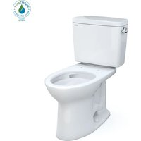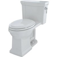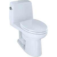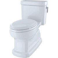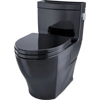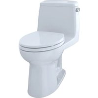
MS854114SG - Toilet TOTO - Free user manual and instructions
Find the device manual for free MS854114SG TOTO in PDF.


User questions about MS854114SG TOTO
0 question about this device. Answer the ones you know or ask your own.
Ask a new question about this device
Download the instructions for your Toilet in PDF format for free! Find your manual MS854114SG - TOTO and take your electronic device back in hand. On this page are published all the documents necessary for the use of your device. MS854114SG by TOTO.
USER MANUAL MS854114SG TOTO
natural_image
Line drawing of a classic toilet with open lid and side door (no text or symbols)| TABLE OF CONTENTS | |||
| Thanks for Choosing TOTO!......2Before Installation......2Common Tools Needed......2Included Parts......2Before Installation......2Installation Procedure......3Maintenance Instructions......4Care and Cleaning......7Warranty......8Rough-In Dimensions......23Replacement Parts......24 | |||
| THANKS FOR USING TOTO! | |||
| The mission of TOTO is to provide the world with healthy, hygienic and more comfortable lifestyles. We design every product with the balance of form and function as a guiding principle. Congratulations on your choice. | |||
| COMMON TOOLS NEEDED | |||
| 10" pipe wrenchCarpenter's LevelTape MeasurePliersMATERIALS REQUIRED:Flexible Supply Tube / ConnectorSupply Stop Valve | ScrewdriverPutty KnifeHacksawMounting (T) Bolts & Nuts (2pc)Wax Ring / Seal | ||
| INCLUDED PARTS | |||
| Check to make sure you have all these parts from the package: | |||
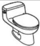 | 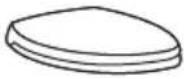 Toilet Seat Set Toilet Seat Set | 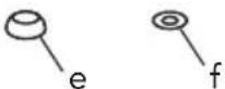 a. Caps (plastic) - 2 b. Base (plastic) - 2Chi a. Caps (plastic) - 2 b. Base (plastic) - 2Chi | |
| BEFORE INSTALLATION | |||
| Read these instructions thoroughly before beginning work.Please leave instructions for customers. These instruction contain maintenance and warranty information.If necessary, remove the existing toilet.IMPORTANT!Due to the powerful performance of our Cyclone, G-Max, E-Max and Power Gravity flushing systems, they are not specified for back-to-back installations. The only means of installing these toilets in a back-to-back situation is when the toilet drain connections incorporate a WYE fitting. Please contact your builder or contractor prior to this installation. | |||
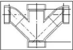 | 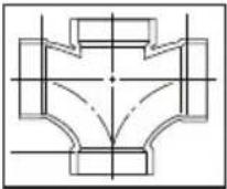 | ||
| Double Combination WYE / 1/8 BendYES | Double Sanitary Tee / Sanitary CrossNO | ||
BEFORE INSTALLATION
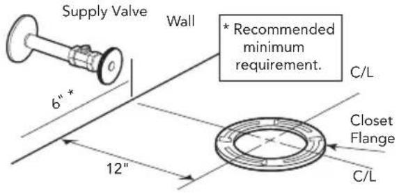
In order for your new TOTO toilet to fit correctly, check the dimensions below:
text_image
Supply Valve Wall * Recommended minimum requirement. 6" * Closet Flange 12" C/L C/LINSTALLATION PROCEDURE
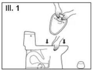
1) Clean any debris out of the closet flange, then install the mounting bolts into the slots of the flange (see Illustration 1). The bolt should be inserted into the slot with its head down and threaded shank pointed upward.
2) Carefully turn the toilet upside down on some padding. Firmly press a new wax seal (not supplied) onto the circular recess around the outlet opening (see Ill. 2). Turn the toilet upright and gently lower it into position over closet flange & bolts. With the toilet properly aligned, press down firmly on both sides of toilet rim to seat wax seal.
CAUTION: Do not move toilet after the wax seal is set.
3) Insert the cap base, washer and thread nuts onto the bolts and hand tighten. Then tighten the bolts an additional 12 turn. Install the bolt caps.
NOTE: If the cap does not fit properly, check that cap base has the correct side up indicated by THIS END UP (THIS PART UP). Or check for interference of the mounting bolt with the cap. Carefully cut the bolt length to allow the cap to fit.
WARNING! Do not over-tighten the nuts. Damage to china or plastic parts may result.
text_image
III. 1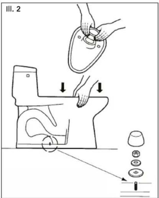
text_image
III. 2INSTALLATION PROCEDURE
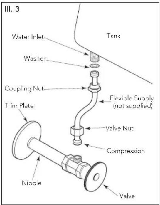
4) Flush water through the flexible supply (not supplied) prior to connection at ballcock/fill valve. Run water into a bucket or similar catch basin until all debris/minerals have cleared the flexible supply, to ensure that the fill valve does not become contaminated. Connect the flexible supply to the ballcock/fill valve shank using a flexible chrome-copper tube connector or equivalent (see III. 3).
CAUTION: Do not over-tighten the nut at the fill valve.
Open the supply stop, checking for leakage. Slightly re-tighten if necessary. The water supply pressure should be 20 to 80 psi static.(Trim Plate, Nipple, Valve & Flexible Supply - not supplied.)
text_image
III. 3 Water Inlet Tank Washer Coupling Nut Flexible Supply (not supplied) Trim Plate Valve Nut Compression Nipple Valve5) NOTE: No ballcock / fill valve adjustments are needed. The water will automatically stop at proper level.
Flush the toilet several times. Check flapper valve for proper operation. Make sure that chain is not tangled and flapper arm is in its proper position.
6) Install the toilet tank lid onto the toilet tank top.
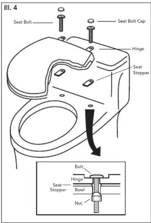
7) Install the toilet seat onto the toilet bowl (see Ill. 4). (Top Mount Bolt Set is included with the bowl). Insert the rubber bushing nuts into the bowl seat holes.
NOTE: Remove the existing seat if necessary.
Place the seat on the bowl and rotate the hinge unit into place while holding seat down on the bowl. Fasten and tighten the bolt from the top with a screwdriver. Replace the bolt cap and the lower lid (if necessary).
text_image
III. 4 Seat Bolt Seat Bolt Cap Hinge Seat Stopper Bolt Hinge Seat Stopper Bowl NutMAINTENANCE INSTRUCTIONS
Replacing the Fill Valve
1) Shut off the water supply to the toilet.
2) Flush toilet and remove remaining water from tank with a sponge.
3) Remove the water supply connection at the fill valve.
4) Remove old fill valve and use damp sponge to clean hole in tank.
5) Place new fill valve inside tank hole.
6) Thread mounting nut onto fill valve shank and tighten the nut.
NOTE: Do not over-tighten. Be sure to install fill valve in a position that does not interfere with the trip lever operation.
7) Connect water supply to fill valve shank and hand-tighten only.
NOTE: Do not overtighten. These are plastic parts. Never use pipe dope on any water supply connection.
8) Attach refill tube to fill valve nipple and clip other end of refill tube to the overflow pipe.
9) Turn water supply ON and check for leaks outside the tank.
NOTE: As water fills the tank, water is also directed into the overflow tube via the refill tube. This additional flow of water is critical to refilling your toilet's bowl. Once the water stops filling the tank, some residual drops of water may drip from the fill valve. This is NORMAL as these drops will subside.
Water Level Adjustment
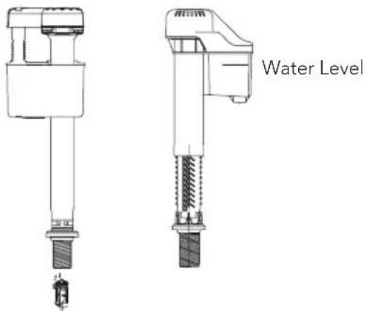
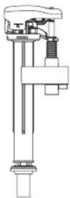
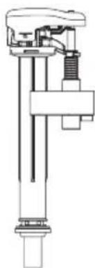
Depending on the manufacturing plant, you may have one of two of the following fill
valves:
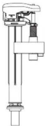
Type A Type B
text_image
Water LevelType C
natural_image
Technical line drawing of a mechanical assembly with no visible text or symbolsFor Type A and Type C Fill Valve:
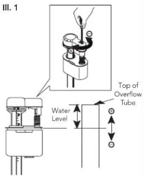
Refer to the water level (WL) setting marked on the inner wall of the tank. Allow the water to fill the tank. Turn the adjustment screw clockwise in the (+) direction to increase the water level height (see Illustration 1). Turn the adjustment screw counter-clockwise in the (-) direction to decrease the water level height. Flush the toilet to verify the correct water level. Adjust as necessary.
For Type B Fill Valve:
There are no water level adjustments. The fill valve has been preset at the factory.
text_image
III. 1 Top of Overflow Tube Water LevelMAINTENANCE INSTRUCTIONS
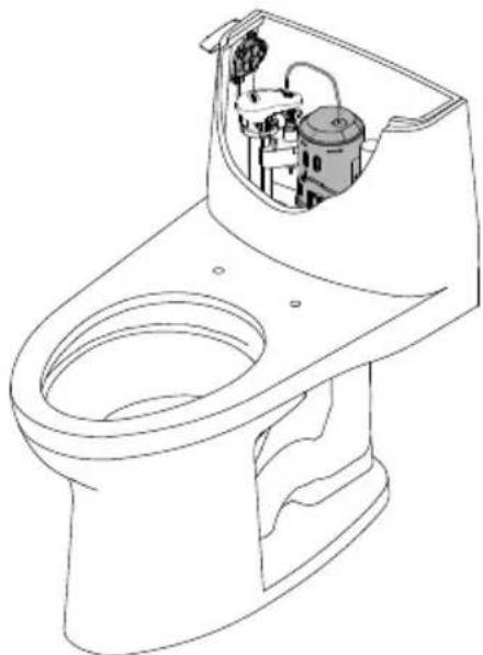
Replacing the Flush Valve (CST604CUFG & CST814CUFG Models)
1) Turn off water supply and flush the toilet. Remove the remaining water from tank with a sponge.
2) Remove the tank lid and place it upside down on a clean surface.
3) Pull the clip on top of trip lever gear box as shown. (see III.1)
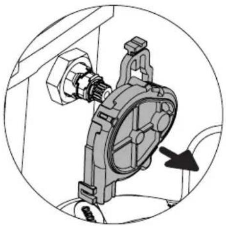
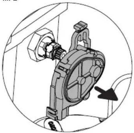
4) Pull gear box away and set on the side as shown. (see III. 2).
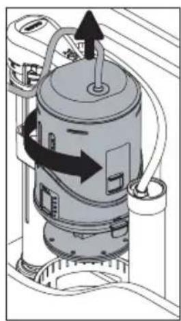
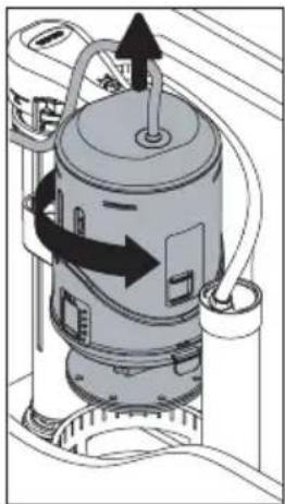
5) Rotate and pull up on the flush tower to remove it. (see III. 3).
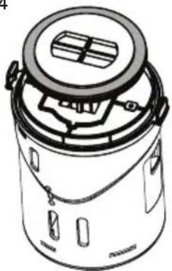
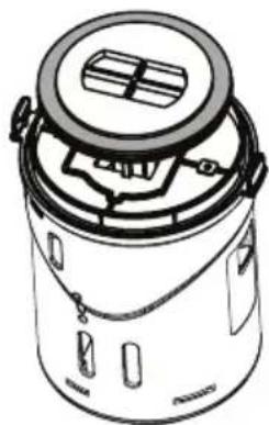
6) Remove the grey rubber seal gasket and rinse under running water to clean. (see Ill. 4).
7) Place the gasket back on the flush tower.
8) Align and place the flush tower into housing and gently press to snap and to lock into place.
9) Replace the trip lever gear box and push down on lever to lock it in place.
10) Carefully install the tank lid back on the tank.
11) Flush the toilet several times making sure the trip lever operates normally.
12) Check the water level in the tank and leak.
natural_image
Line drawing of a toilet with internal components (no text or symbols)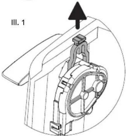
natural_image
Technical line drawing of a mechanical assembly with a gear and mounting bracket (no text or symbols)III. 4
III. 2
natural_image
Mechanical assembly diagram showing a motor and housing component, no text or symbols presentIII. 3
natural_image
Diagram of a cylindrical device with internal components and directional arrows indicating flow or movement (no text or symbols)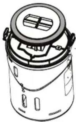
natural_image
Line drawing of a cylindrical container with lid and internal components (no text or symbols)MAINTENANCE INSTRUCTIONS
Replacing the Drain Valve
1) Shut off the water supply.
2) Flush the toilet to remove the water inside the tank.
3) Remove the tank lid and place somewhere safe.
NOTE: Before removing anything from the tank, note the placement of the drain valve, chain and refill tube.
4) Unhook the refill tube from the overflow tube of the drain valve.
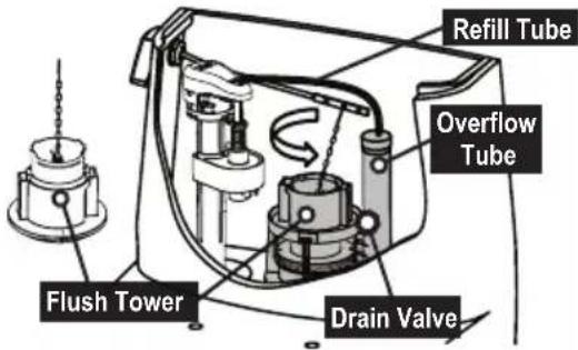
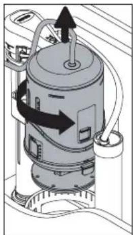
5) Unlock the flush tower unit by turning counter-clockwise with the chain hook still attached to the trip lever (ill.1).
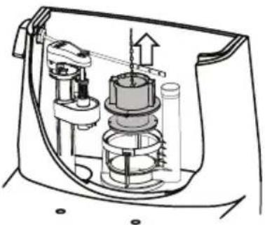
6) Unhook the chain from the trip lever and remove the flush tower unit (ill. 2).
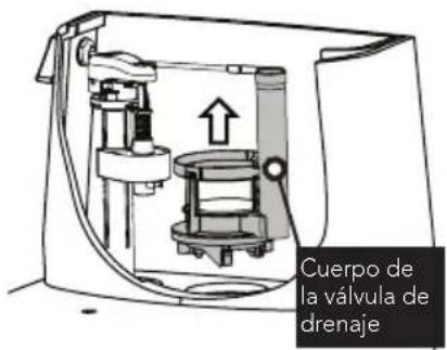
7) Unscrew the three screws from the drain valve body.
IMPORTANT: Make sure not to turn more than seven full turns as the black mounting block can fall into the water channel.
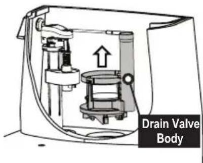
8) Remove the drain valve body from the tank (ill. 3).
9) Replace the drain valve in the same position as the former drain valve.
10) Tighten the screws, applying light torque on each screw before final torque on all three screws.
11) Install the flush tower unit onto the drain valve body and turn clockwise to lock the part.
12) Hook the chain back to its original location, and the refill tube.
13) Turn the water supply back on and check for any leak after the tank has been filled.
ill. 1
text_image
Flush Tower Refill Tube Overflow Tube Drain Valveill. 2
natural_image
Technical diagram of a mechanical device with internal components and directional arrow (no text or labels)ill. 3
text_image
Drain Valve BodyCARE AND CLEANING
WARNING!
DO NOT USE IN-TANK BOWLCLEANERS.
The use of high concentration of chlorine or chlorine-related products can seriously damage fittings in the tank. This damage can cause leakage and property damage. TOTO shall not be responsible or liable for any tank fitting failure or damage caused by the use of in-tank bowl cleaners.
WARRANTY
- TOTO warrants its vitreous china products ("Product") to be free from defects in materials and workmanship during normal use when properly installed and serviced, for a period of one (1) year from date of purchase. This limited warranty is extended only to the ORIGINAL PURCHASER of the Product and is not transferable to any third party, including but not limited to any subsequent purchaser or owner of the Product. This warranty applies only to TOTO Product purchased and installed in North, Central and South America.
- TOTO's obligations under this warranty are limited to repair, replacement or other appropriate adjustment, at TOTO's option, of the Product or parts found to be defective in normal use, provided that such Product was properly installed, used and serviced in accordance with instructions. TOTO reserves the right to make such inspections as may be necessary in order to determine the cause of the defect. TOTO will not charge for labor or parts in connection with warranty repairs or replacements. TOTO is not responsible for the cost of removal, return and/or reinstallation of the Product.
- This warranty does not apply to the following items:
a. Damage or loss sustained in a natural calamity such as fire, earthquake, flood, thunder, electrical storm, etc.
b. Damage or loss resulting from any accident, unreasonable use, misuse, abuse, negligence, or improper care, cleaning, or maintenance of the Product.
c. Damage or loss resulting from sediments or foreign matter contained in a water system.
d. Damage or loss resulting from improper installation or from installation of the Product in a harsh and/or hazardous environment, or improper removal, repair or modification of the Product. (NOTE: Product model codes allow a maximum of 80 PSI. Check local codes or standards for requirements).
e. Damage or loss resulting from electrical surges or lightning strikes or other acts which are not the fault of TOTO or which the Product is not specified to tolerate.
f. Damage or loss resulting from normal and customary wear and tear, such as gloss reduction, scratching or fading over time due to use, cleaning practices or water or atmospheric conditions.
g. Tank flushing mechanisms of plastic or rubber moving parts.
h. Toilet seats of plastic, wood or metal.
- In order for this limited warranty to be valid, proof of purchase is required. TOTO encourages warranty registration upon purchase to create a record of Product ownership at http://www.totousa.com. Product registration is completely voluntary and failure to register will not diminish your limited warranty rights.
- THIS WARRANTY GIVES YOU SPECIFIC LEGAL RIGHTS. YOU MAY HAVE OTHER RIGHTS WHICH VARY FROM STATE TO STATE, PROVINCE TO PROVINCE OR COUNTRY TO COUNTRY.
- To obtain warranty repair service under this warranty, you must take the Product or deliver it prepaid to a TOTO service facility together with proof of purchase (original sales receipt) and a letter stating the problem, or contact a TOTO distributor or products service contractor, or write directly to TOTO U.S.A., INC., 1155 Southern Road, Morrow, GA 30260 (678) 466-1300 or (888) 295-8134, if outside the U.S.A. If, because of the size of the Product or nature of the defect, the Product cannot be returned to TOTO, receipt by TOTO of written notice of the defect together with proof of purchase (original sales receipt) shall constitute delivery. In such case, TOTO may choose to repair the Product at the purchaser's location or pay to transport the Product to a service facility.
WARNING! TOTO shall not be responsible or liable for any failure of, or damage to, this Product caused by either chloramines in the treatment of public water supply or cleaners containing chlorine (calcium hypochlorite). NOTE: The use of a high concentrate chlorine or chlorine related products can seriously damage the fittings. This damage can cause leakage and serious property damage.
THIS WRITTEN WARRANTY IS THE ONLY WARRANTY MADE BY TOTO. REPAIR, REPLACEMENT OR OTHER APPROPRIATE ADJUSTMENT AS PROVIDED UNDER THIS WARRANTY SHALL BE THE EXCLUSIVE REMEDY AVAILABLE TO THE ORIGINAL PURCHASER. TOTO SHALL NOT BE RESPONSIBLE FOR LOSS OF THE PRODUCT OR FOR OTHER INCIDENTAL, SPECIAL OR CONSEQUENTIAL DAMAGES OR EXPENSES INCURRED BY THE ORIGINAL PURCHASER, OR FOR LABOR OR OTHER COSTS DUE TO INSTALLATION OR REMOVAL, OR COSTS OF REPAIRS BY OTHERS, OR FOR ANY OTHER EXPENSE NOT SPECIFICALLY STATED ABOVE. IN NO EVENT WILL TOTO'S RESPONSIBILITY EXCEED THE PURCHASE PRICE OF THE PRODUCT. EXCEPT TO THE EXTENT PROHIBITED BY APPLICABLE LAW, ANY IMPLIED WARRANTIES, INCLUDING THAT OF MERCHANTABILITY OR FITNESS FOR USE OR FOR A PARTICULAR PURPOSE, ARE EXPRESSLY DISCLAIMED. SOME STATES DO NOT ALLOW LIMITATIONS ON HOW LONG AN IMPLIED WARRANTY LASTS, OR THE EXCLUSION OR LIMITATION OF INCIDENTAL OR CONSEQUENTIAL DAMAGES, SO THE ABOVE LIMITATION AND EXCLUSION MAY NOT APPLY TO YOU.
natural_image
Pure mechanical component diagram without any text, numbers, or symbols
natural_image
Technical line drawing of a mechanical component with threaded shaft and base (no text or symbols)Tipo C
natural_image
Technical line drawing of a mechanical assembly with no visible text or symbolsnatural_image
Line drawing of a standard toilet with internal components (no text or labels)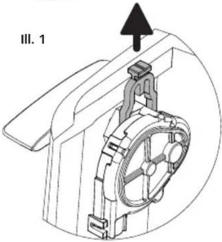
natural_image
Technical line drawing of a mechanical assembly with no visible text or symbolsIII. 4
natural_image
Line drawing of a cylindrical container with internal compartments and a lid (no text or symbols)III. 2
natural_image
Mechanical assembly diagram showing a motor or gear mechanism inside a housing (no text or symbols visible)III. 3
natural_image
Diagram of a cylindrical device with internal components and directional arrows indicating flow or movement (no text or symbols)natural_image
Technical diagram of a mechanical device with internal components and directional arrows (no text or labels)ill. 3
natural_image
Technical line drawing of a mechanical assembly with no visible text or symbols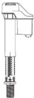
natural_image
Technical line drawing of a mechanical device with threaded shaft and base (no text or symbols)Tipo C
natural_image
Technical line drawing of a mechanical assembly with no visible text or symbolsnatural_image
Mechanical assembly diagram showing a motor and gear assembly inside a housing (no text or labels)III. 3
natural_image
Diagram of a cylindrical device with internal components and directional arrows indicating flow or movement (no text or symbols)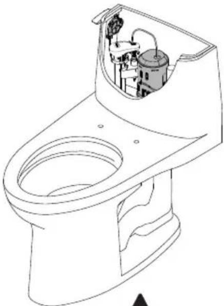
natural_image
Line drawing of a standard toilet with internal components (no text or labels)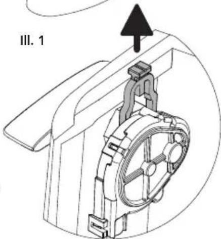
natural_image
Technical line drawing of a mechanical component with a labeled section III. 1 (no text or symbols on the diagram itself)III. 4
natural_image
Line drawing of a cylindrical container with lid and internal compartments (no text or symbols)INSTRUCTIONS D'ENTRETIEN
natural_image
Technical diagram of a mechanical device showing internal components and flow direction (no text or labels)ill. 3
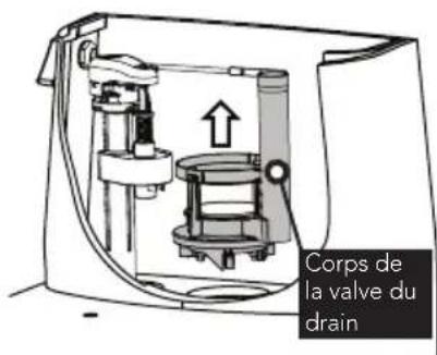
text_image
Corps de la valve du drainENTRETIEN ET NETTOYAGE
AVERTISSEMENT:
* Check for correct dimension
NOTE: Compensate accordingly for any baseboard blocks.
| Model A B C D | ||||
| MS604114CEF(G) 28-3/8" 16-1/8" | 16-1/2" 28-3/4" | |||
| MS604114CUF(G) 28-3/8" 16-1/8" | 16-1/2" 28-3/4" | |||
| MS634114CEF(G) 28-3/8" 16-1/8" | 16-1/2" 25-5/8" | |||
| MS814224CEF(G) 28-1/2" 16-1/8" | 16-1/4" 29-1/4" | |||
| MS814224CUF(G) 28-1/2" 16-1/8" | 16-1/4" 29-1/4" | |||
| MS853113E(S) 26-1/2" 14-5/8" 16-1/2" 27-1/8" | ||||
| MS854114E(S)(G) 28" 14-5/8" 16-1/2" 27-1/8" | ||||
| MS854114E(S)L(G) | 28-1/8" 16-1/2" 16-1/2" | 29-1/8" | ||
| MS863113(E) | 26-1/2" 14-5/8" 16-1/2" | 23-1/2" | ||
| MS864114(E) | 28" 14-5/8" 16-1/2" 23 | -1/2" | ||
| MS864114L | 28-1/8" 16-1/2" 16-1/2" | 25-1/2" | ||
| MS924154F | 28-1/8" 16-1/2" 18-3/8" | 27-3/8" |
REPLACEMENT PARTS / REFACCIONES / PIÈCES DE RECHANGE
natural_image
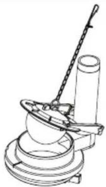
Technical line drawing of a mechanical device with a cylindrical component and a curved handle (no text or symbols)For flapper type drain valve
| ModelModeloModèle | FlapperTapónClapet | Fill ValveVálvula de llenadoRobinet de remplissage | Flush ValveVálvula de la cisternaSoupape de vidange | Trip LeverPalanca de descargaLevier de déclenchement |
| CST604CEF(G) THU499S TSU51A | THU013PR THU004#XX | |||
| CST604CEFRG THU499S TSU51A | THU013PR THU341#CP | |||
| CST604CUF(G) 9BU094 TSU55A THU421-A THU422#CP | ||||
| CST634CEF(G) THU499S TSU53A THU245P-3R THU004#XX | ||||
| CST853 THU499S TSU54A THU002Z THU004#XX | ||||
| CST853E THU499S TSU51A | THU251PR THU004#XX | |||
| CST854 THU499S TSU54A THU002Z THU004#XX | ||||
| CST854E(L) THU499S TSU51A THU251PR THU004#XX | ||||
| CST854ELR THU499S TSU51A THU251PR THU341#CP | ||||
| CST863 THU499S TSU54A THU001Z THU004#XX | ||||
| CST863E THU499S TSU54S | THU245P-3R THU004#XX | |||
| CST864(L) THU499S | TSU54S | THU001Z | THU004#XX | |
| CST864E THU499S TSU54S | THU245P-3R THU004#XX | |||
| CST924F THU499S | TSU54S | THU128Z-1 | THU147#XX |
REPLACEMENT PARTS / REFACCIONES / PIÈCES DE RECHANGE
natural_image
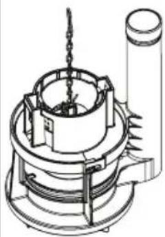
Technical line drawing of a mechanical device with no visible text or symbolsFor flush tower type drain valve
| Model Modelo Modèle | Drain Valve Válvula de drenaje Valve du drain | Flush Tower Torre de descarga Chasse d'Eau | Seal Gasket Junta de sellado joint d'étanchéité | Fill Valve Válvula de lenado Robinet de remplissage | Trip Lever Palanca de descarga Levier de déclenchement |
| CST604CEF(G)T | THU451.10A-A | THU440 THU | 407 TSU51A | THU004#XX | |
| CST604CEFRGT | THU451.10A-A | THU440 THU | 407 TSU51A | THU341#CP | |
| CST634CEF(G)T | THU460.6D-A | THU460 THU4 | 407 TSU53A | THU004#XX | |
| CST814CEF(G) | THU451.10A-A | THU440-A THU | 407 TSU51A | THU458#XX | |
| CST814CUF(G) | THU465 N/A | THU474 TSU55 | A THU466#XX | ||
| CST853T THU46 | 0.15E-A THU | 460 THU407 | TSU54A THU | 004#XX | |
| CST853ET | THU453.10C-A | THU440 THU | 407 TSU51A | THU004#XX | |
| CST854T THU46 | 0.15E-A THU | 460 THU407 | TSU54A THU | 004#XX | |
| CST854E(L)(R)T | THU453.10C-A | THU440 THU | 407 TSU51A | THU004#XX | |
| CST863ET | THU460.6D-A | THU460 THU | 407 TSU54A | THU004#XX | |
| CST864ET | THU460.6D-A | THU460 THU | 407 TSU54A | THU004#XX |
TOTO®
TOTO® U.S.A., Inc. 1155 Southern Road,
Morrow, Georgia 30260
Tel: 888-295-8134 Fax: 800-699-4889
www.totousa.com
0GU013Z-11
Rev Date: 08/16