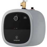
ES025A3G - Electric water heater WESTINGHOUSE - Free user manual and instructions
Find the device manual for free ES025A3G WESTINGHOUSE in PDF.


| Product type | Electric water heater |
| Brand | Westinghouse |
| Model | ES025A3G |
| Capacity | 2.5 gallons (9.5 liters) |
| Dimensions (H x W x D) | 16.89 x 13.39 x 13.39 inches (429 x 340 x 340 mm) |
| Weight | Approximately 15 lb (6.8 kg) |
| Power supply | 120 VAC, 1440 W, 12 A, single-phase |
| Temperature range | 55 °F to 145 °F (12.8 °C to 62.8 °C) |
| Maximum water pressure | 150 psi (10.3 bar) |
| Mounting type | Wall-mounted (vertical only) or floor-standing |
| Cold / hot water connection | 1/2 NPT male (blue / red) |
| Safety valve | Temperature and pressure (T&P) 3/4 NPT male, 150 psi |
| Heating element | 1440 W, removable and descalable |
| Magnesium anode | Diameter 20 mm, length 120 mm (replaceable) |
| Thermostat | Adjustable, with high temperature switch (resettable) |
| Main functions | Water heating, temperature adjustment, anti-freeze protection (not specified) |
| Maintenance and cleaning | Annual draining, anode inspection, descaling of heating element |
| Safety | Mandatory grounding, T&P valve, high temperature safety switch, recommended drip pan |
| Spare parts and repairability | Heating element, thermostat, anode, gasket, cover, knob, lamp, power cord |
| General information | Warranty subject to conditions, customer service: +1 833 566 1779, support@tl.westinghouse.com |
Frequently Asked Questions - ES025A3G WESTINGHOUSE
User questions about ES025A3G WESTINGHOUSE
0 question about this device. Answer the ones you know or ask your own.
Ask a new question about this device
Download the instructions for your Electric water heater in PDF format for free! Find your manual ES025A3G - WESTINGHOUSE and take your electronic device back in hand. On this page are published all the documents necessary for the use of your device. ES025A3G by WESTINGHOUSE.
USER MANUAL ES025A3G WESTINGHOUSE
Electric Mini-Tank Water Heater
Products:
ES025
ES040
ES080
CONTENTS
1 Safety Information 03
1.1 Safety Definitions 03
1.2 Safety Messages 03
2 Information about the product 05
2.1 Models overview 05
2.2 Dimensions 06
2.3 Technical data 07
3 Installation instructions 08
3.1 Mounting the heater 08
3.2 Pipe connections 08
3.3 Closed system thermal expansion 09
4 Use 10
4.1 Starting and testing 10
4.2 Temperature setting 10
5 Maintenance 11
5.1 Removing the cover 11
5.2Draining the heater 11
5.3 Inspecting the anode rod 11
5.4 Removing the heating element 11
5.5 Descaling the heating element 12
6 Replacement of parts 13
6.1 Changing the anode rod 13
6.2 Changing the heating element 13
6.3 Changing the thermostat 13
7 Troubleshooting 14
7.1 Fault Assessment and Troubleshooting 14
7.2 Resetting High Limit Switch 15
8 Interior components diagram 16
French 17
SAVE THESE INSTRUCTIONS
1 Safety Information
1.1 Safety Definitions
This manual has safety information and instructions to help you eliminate or reduce the risk of accidents and injuries.

DANGER
Indicates an imminently hazardous situation which, if not avoided, will result in death or serious injury.

WARNING
Indicates a hazardous situation that, if not avoided, could result in death or serious injury.

CAUTION
Indicates a hazardous situation which, if not avoided, could result in property damage and minor or moderate injury.

NOTICE
This symbol indicates important information where there is no risk to people or property.
Additional symbols
| Symbol | Explanation |
| ■ | Step in an action sequence |
| → | Cross-reference to another part of the document |
| • | List entry |
1.2 Important Safety Instructions

WARNING
When using electrical appliances, safety precautions to reduce the risk of fire, electric shock or injury to persons should be followed.
- READ ALL INSTRUCTIONS BEFORE USING THIS WATER HEATER.
- This water heater must be grounded. Connect only to properly grounded outlet. See
"GROUNDING INSTRUCTIONS" found on (specific page or section to be included).
- Install or locate this water heater only in accordance with the provided installation instructions.
- Use this water heater only for its intended use as described in this manual.
- Do not use an extension cord set with this water heater. If no receptacle is available adjacent to the water heater, contact a qualified electrician to have one properly installed.
- As with any appliance, close supervision is necessary when used by children.
- Do not operate this water heater if it has a damaged cord or plug, if it is not working properly, or if it has been damaged or dropped.
- This water heater should be serviced only by qualified service personnel. Contact nearest authorized service facility for examination, repair, or adjustment.
- Do not use multi-outlet adaptors (i.e. power strips) with this water heater.
- Failure to inspect the anode rod at least once a year could cause the tank to fail and leak. This condition is not covered under the manufacturer's warranty.
- Any water heater should be installed in such a manner that if it should leak, the resulting flow of water will not cause damage to the area in which it is installed. National Plumbing codes require a drain pan for any water heater installation. Failure to install one is the sole responsibility of owner and/or installer. Reference UPC 2006 (Uniform Plumbing Code) Section 508.1, or IPC 2006 (International Plumbing Code) Section 504.7.

CAUTION
The installer should review the contents of this manual with the owner upon completion of installation, and the manual should be left with the owner and placed in a location close to the installation.

CAUTION
The manufacturer cannot be responsible for the damages caused by improper installation or by failure to follow instructions in this manual. Comply with the installation instructions before completing electric connection.

CAUTION
The thermostat has been pre-set at the factory at a temperature equal or below 51.7^ 125F ( Fig.1)
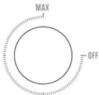

Fig. 1
CAUTION
Any water heater should be installed in such a manner that if it should leak, the resulting flow of water will not cause damage to the area in which it is installed. National Plumbing codes require a drain pan for any water heater installation. Failure to install one is the sole responsibility of owner and/or installer. Reference UPC 2006 (Uniform Plumbing Code) Section 508.1, or IPC 2006 (International Plumbing Code) Section 504.7.

DANGER
Hydrogen gas is produced in a hot water system served by this heater that has not been used for a long period of time (2 weeks or more). Hydrogen gas is extremely flammable. To reduce the risk of injury under these conditions, it is recommended that the hot water faucet be opened for several minutes at the kitchen sink before using any electrical appliance connected to the hot water system. When hydrogen is present, there will probably be an unusual sound such as air escaping through the pipe as the water begins to flow. There should be no smoking or open flame near the faucet at the time it is open.

CAUTION
Prior to connecting the power supply, ensure tank is full of water and system is purged of air.

NOTICE
Tank failure due to neglecting to maintain the anode rod is not covered under warranty (see Section 5 Maintenance).

WARNING
This product can expose you to lead, which is known to the state of California to cause cancer and birth defects or other reproductive harm. For more information, go to www.P65 warnings.ca.gov.
2 Information about the product
2.1 Models overview
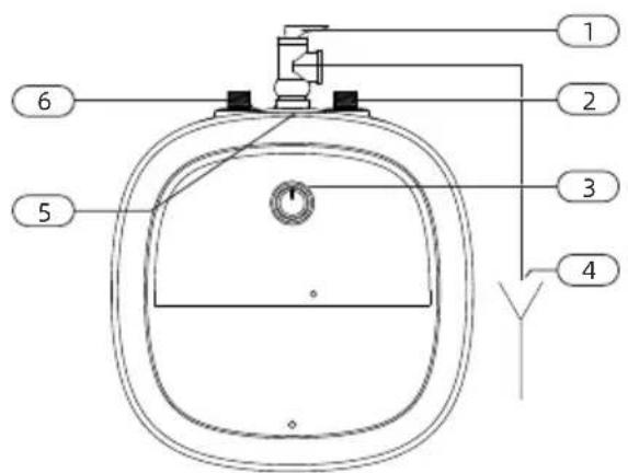
Fig. 2
- Temperature & pressure relief valve, 3 / 4 NPT male
- Cold water inlet (BLUE) 1 / 2 NPT male (ES025 and ES040)
Cold water inlet (BLUE) 3 / 4 NPT male (ES080 equipped with converter)
- Temperature Adjustment Knob
- Temperature & pressure relief valve discharge line to drain
- 3 / 4 NPT female tapping for relief valve
- Hot water outlet (RED) 1/2 NPT male (ES025 and ES040)
Hot water outlet (RED) 3 / 4 NPT male (ES080 equipped with converter)
2.2 Dimensions
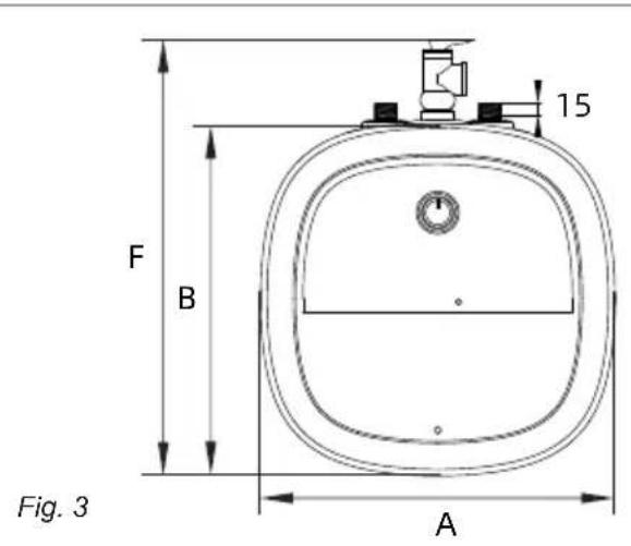
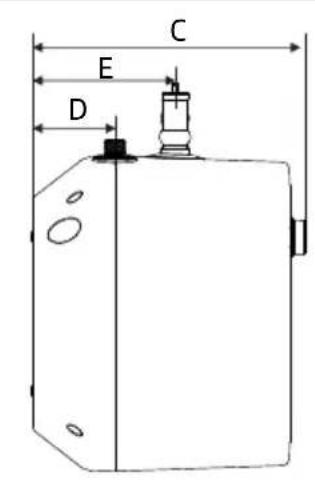
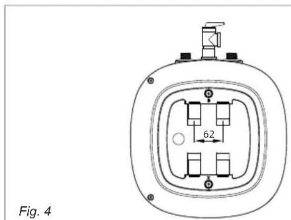
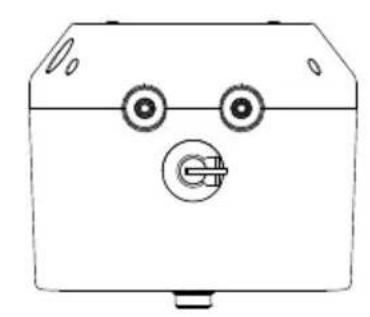
| Capacity | Dimensions (inch) | |||||
| A | BCDE | F | ||||
| 2.5 gal | 13.39 | 13.39 | 11.42 | 3.58 | 6.14 | 16.89 |
| 4.0 gal | 14.96 | 14.96 | 12.80 | 4.13 | 6.69 | |
| 8.0 gal | 17.32 | 17.32 | 15.35 | 5.20 | 8.38 | 20.82 |
- Vertically installation only
2.3 Technical data
| Model (Units) | ES025 ES040 ES080 | ||
| Capacity (Gallons) | 2.5 | 4.0 | 8.0 |
| Voltage (VAC) | 120 for each model | 120 for each model | 120 for each model |
| Power at 120 VAC (Watts) | 1440 | 1440 | 1440 |
| Maximum water pressure (Psi) | 150 | 150 | 150 |
| Amperage (Amps) | 12.0 for each model | 12.0 for each model | 12.0 for each model |
| Phases | 1 | 1 | 1 |
| Temperature range (°F) | 55-145 55-14555-145 | ||
3 Installation instructions
3.1 Mounting the heater
Wall mounting
NOTICE: Material damages! Use screws that are suitable for the
Use screws that are suitable for the wall material and the weight of the heater.
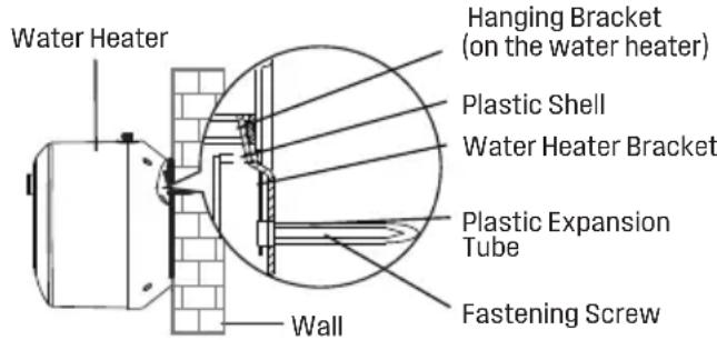
After the installation position of the water heater is determined, drill two holes with a spacing of 2.44 inch and a diameter of 0.394 inch in the horizontal direction of the wall according to the size as shown in the following figure, and the hole depth shall not be less than 2.76 inch. Insert two plastic expansion tubes into the hole, and fix the water heater bracket with fastening screws.
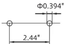
Install the wall hole
Unclench the plastic shell in the back of water heater before hanging it, then align the two hanging holes on the back of the water heater with the two hooks of the water heater bracket and pull down with force to make the hanging holes hang into the hook.

CAUTION
The appliance must be hung securely to prevent personal injury and property damage from falling.
Floor mounting
- Heater can sit on floor. When the water heater is placed on the floor, additional reinforcement is required
3.2 Pipe connections
- Connect the cold water inlet pipe to the inlet tapping (marked with a blue ring).
- Ensure a isolation valve is installed on the cold water supply to the water heater.
- Connect the hot water outlet pipe to the outlet tapping (marked with a red ring).

CAUTION
To reduce the risk of excessive pressures and temperatures in this water heater:
Install the supplied temperature and pressure protective equipment required by local codes but not less than a combination temperature and pressure relief valve certified by a nationally recognized testing laboratory that maintains periodic inspection of production of listed equipment or materials, as meeting the requirements for Relief Valves and Automatic Gas Shut-off Devices for Hot Water Supply Systems,ANSIZ21.22.
The supplied temperature and pressure relief valve is marked with a maximum set pressure (150 psi) that does not exceed the marked maximum working pressure of the water heater.
Install the valve in the opening provided and marked for this purpose in the water heater.
- Orient it or provide tubing so that any discharge from the valve will exit within 6 inches above, or at any distance below, the structural floor, and cannot contact any live electrical part. The discharge opening must not be blocked or reduced in size under any circumstances.
NOTICE Wrap the
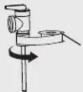
Wrap the Teflon tape around the threaded opening of the pressure relief valve at least 15 times (approximately 1.2 meters in length) in order to prevent water leakage.
Wrap at least 15 times
Teflon tape
NOTICE
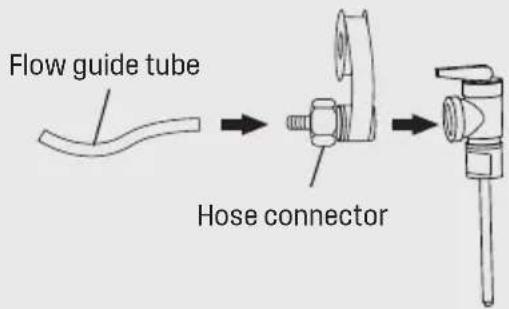
Wrap at least 8 turns (approximately 25.2 inches (65~cm) ) of Teflon tape around the threaded opening of the hose connector.
National Plumbing codes may require a drain pan for the water heater installation. Failure to install one is the sole responsibility of owner and/or installer. Reference UPC (Uniform Plumbing Code), or IPC (International Plumbing Code).
3.3 Closed system thermal expansion
Periodic discharge of the temperature and pressure relief valve or failure of the element gasket may be due to thermal expansion in a closed water supply system. The water utility supply meter may contain a check valve, backflow preventer or water pressure reducing valve which will create a closed water system.
During the heating cycle of the water heater, the water expands causing pressure inside the water heater to increase.
The temperature and pressure relief valve may discharge hot water under these conditions which results in a loss of energy and a build-up of lime on the relief valve seat.
The temperature and pressure relief valve may discharge hot water under these conditions which results in a loss of energy and a build-up of lime on the relief valve seat.
To prevent this from happening, there are two recommendations:
- Install a diaphragm-type expansion tank that is suitable for potable water on the cold water supply line. A minimum 0.5 gallon expansion tank should be used.
Contact the local water supplier or plumbing inspector for information on how to control this situation. Do not plug the temperature and pressure relief valve.
4 Use
4.1 Starting and testing

CAUTION
DO NOT supply power to water heater until filled with water.
To fill the heater:
- Open supply valve for water heater to fill with water.
- Open hot water tap(s) supplied by the water heater to purge air out of the system. Once air is purged, close hot water tap.
Visually check for any leaks.
Turning heater on
For models which are not fitted with a switch:
Supply power to the water heater by plugging in the power cord.
If the light does not come on, turn the control knob in a clockwise direction.
The light will come on until water temperature has reached the thermostat temperature setting. The light will come back on any time the water temperature inside the tank drops below the thermostat setting.

DANGER
If user's water pressure is high, TP valve may relieve pressure under high pressure during the heating process, water temperature will be over 145^ after pressure relief, which can cause severe burns instantly or death from scalds. Please take attention!
4.2 Temperature setting
To fill the heater:
The temperature of the hot water is adjusted by rotating the knob M (Fig.5) located on the front cover. Temperature range is 55 - 145^ .
Turn the knob clockwise to increase temperature.
Turn the knob counter-clockwise to decrease temperature.
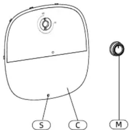
Fig. 5
5 Maintenance

CAUTION
Do not attempt to repair this water heater yourself. Call a service person for assistance. Always turn off the power supply to the heater prior to servicing or draining the heater.

NOTICE
For most of these operations, the water will have to be drained from the heater. For all of these operations the cord should be disconnected and the front cover removed.
5.1 Removing the cover
Remove rubber seal which covers the Phillips screw(Fig. 5 [S]), and unscrew the Phillips screw.
The cover (Fig. 5, [C]) can now be removed by slightly rotate. When reassembling, work in the opposite way being careful to insert the tongue of the cover into the slot.
5.2 Draining the heater
If the heater has been installed with flexible hoses:
Shut off the power supply.
Turn the heater upside down over a sink to drain the water out of it.
5.3 Inspecting the anode rod
If the heater has been installed with flexible hoses:
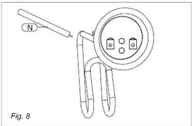
The purpose of the anode rod (Fig. 8, [N]) is to protect the tank against corrosion. It is critical that the anode rod be inspected once a year to determine whether it requires replacement. To access the anode rod, the heating element must be removed (see Section 5.4 Removing the heating element). Upon inspection, the anode rod surface should appear smooth. If the rod surface appears pitted, bumpy, rusty, or if the rod is
missing completely, then it must be replaced.
To access the anode rod:
- Remove the heating element (see Section 5.4 Removing the heating element).
Original anode rod sizes
Length 4.72" Diameter 0.787"
Certain installations may require more frequent replacement of the anode rod:
recirculation applications
- poor water quality
galvanic/electrolytic corrosion
high flow applications
In the event of poor water quality, we recommends consulting a local water treatment professional for water treatment options. Always ensure the water heater is grounded. Damage resulting from poor water quality or failure to replace the anode rod is not covered under the manufacturer's warranty. For additional questions, please call Technical Service.
5.4 Removing the heating element
Take out the power cord L from the plastic part. (Fig. 6)
Use a cross screwdriver to unscrew the 3-in-1 cross screw J on the heating element terminals of red wire J and blue wire C. (Fig. 6)
Remove the wire nail I and press the thermostat capillary G and the thermal cut-out capillary H, and take it out of the blind tube opening. (Fig. 6)
Loosen the 5 nuts and spring washer on the heating element pressing plate A with the sleeve, and take out the heating element pressing plate A. (Fig. 6)
Remove heating element B. (Fig. 6)
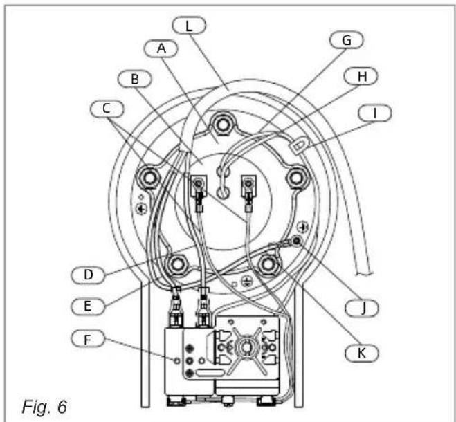
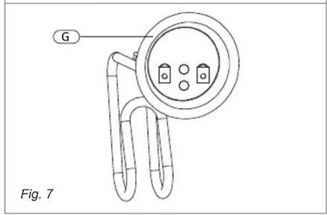
A. Heating Element Pressing Plate
B. Heating Element
C.Wire
D. Live Wire
E. Null Wire
F. Return Pin
G. Thermostat Capillary
H. Thermal cut-out Capillary
I. Wire Nail
J. 3-in-1 Cross Screw
K. Ground Wire
L. Power Cord
5.5 Descaling the heating element
Scale deposits can affect the heating capability of the element.
Heavy scale can even cause damage to the element. The element can be descaled either chemically or manually:
Soak the element in white vinegar or other.
descaling solution.
Once descaled, rinse well with fresh water, to which you should add some baking soda. -or-
Once the element has dried, use a soft brush (non metallic to prevent damaging the stainless steel sheath) on element.
Brush the dried mineral off.
Reinstall the element with gasket and make the wire connections.

NOTICE
Make sure the tank has been refilled with water before restoring power.
6 Replacement of parts
6.1 Changing the anode rod
Turn off the power supply and drain the heater (see Draining the Heater).
Remove heating element (see previous section).
Unscrew anode rod from threaded connection.
Remove and replace the anode rod (Fig. 8, [N]).
Reinstall heating element.
- Refill tank with water before restoring power.
6.2 Changing the heating element
Turn off power supply and drain the heater (see Draining the Heater).
Remove the heating element (see section on Removing the Heating Element).
Install new element with gasket, making sure the gasket and element are positioned correctly. Tighten the retaining nuts and make the wire connections.
Ensure that the thermostat temperature sensor is inserted into the well located on the element assembly and secured with black rubber grommet.
- Refill tank with water before restoring power.
6.3 Changing the thermostat
Turn off power supply.
- Disconnect the 2 wire connectors on thermostat.
Loosen the two brass screws at right side of thermostat and pull wires out.
- Remove thermostat temperature sensor from well located in element assembly.
- Unscrew and remove the two Phillips screws holding the thermostat onto the tank.
Install new thermostat and re-attach wiring and screws.
Ensure that the thermostat temperature sensor is inserted into the well located on the element assembly and secured with black rubber grommet.
7 Troubleshooting
7.1 Fault Assessment and Troubleshooting
| Problem Solution | |
| Water does not get hot | Make sure the power supply is on and working. |
| If light does not come on, check that the high limit reset button is pushed in; follow steps in section 7.1. | |
| If the indicator light works properly but temperature does not get hot at the tap, test for a plumbing crossover; shut off cold supply to heater and open hot water tap. There should be no water flowing. Any continued flow indicates a crossover which will effect the temperature and will need to be corrected. | |
| Call a qualified service technician to test the resistance of the heating element (8-10 ohms). Heating element should be replaced if readings are outside these values. | |
| Light not on | If the light does not come on, but water gets hot, check for faulty bulb. |
| Check high limit reset button; follow steps in section 7.2. | |
| Brown water | Brown or rusty water indicates a "spent" anode rod and possible deterioration of the tank body. Inspect the tank for leaks. Check anode rod (see section on changing the anode rod). |
| Leaking | Check water fittings and T & P fitting on top of tank. Remove front cover and inspect heating element gasket. |
| If tank is leaking call Fogatti Water Heating for warranty claim if still within warranty period. | |
| Check anode rod (see section on changing the anode rod). | |
7.2 Resetting High Limit Switch
Occasionally, the high temperature limit shut off device may trip the reset. This occurs when water temperature exceeds 190^ . The shut off device may also trigger from a power outage or electrical storm. To reach the thermostat:
- Disconnect power cord and remove installation cover.
Firmly press reset button (Fig. 9, [B]) with the tip of a ball point pen or similar object.
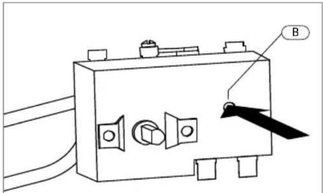
Fig. 9
A click indicates the reset was tripped.
Reconnect power
IMPORTANT:
Check the operation of the thermostat: Turn temperature dial from high to low.
If the red light does not go off on low setting: Turn off power supply and call a service person to replace the thermostat.
If the red light does go off the thermostat is working well: Place dial setting to desired setting.

NOTICE
A lower setting is more economical and reduces the risk of scalding.
Replace cover plate.

CAUTION
Call a technician if the high limit needs to be reset frequently.
8 Interior components diagram
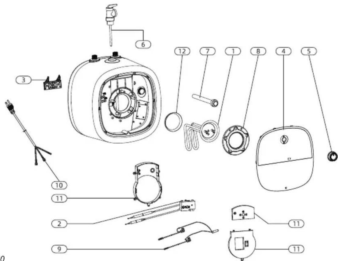
Fig. 10
| Part | Description |
| 1 | Heating element 1440W |
| 2 | Thermostat |
| 3 | Heater wall hanging bracket |
| 4 | Plastic cover |
| 5 | Knob |
| 6 | Valve T&P 3/4 (attached In the product package) |
| 7 | Magnesium anode D:20, L:120 mm |
| 8 | Gasket with 5 bolts |
| 9 | Lamp |
| 10 | Power cable |
| 11 | Fireproof component |
| 12 | Gasket |
Table de matière
3.3 Closed system thermal expansion
and Westinghouse are trademarks of Westinghouse Electric Corporation.
Used under license by Fogatti Holdings Limited.

- Electric Mini-Tank Water Heater
- CONTENTS
- Safety Information 03
- Information about the product 05
- Installation instructions 08
- Use 10
- Maintenance 11
- Replacement of parts 13
- Troubleshooting 14
- Interior components diagram 16
- French 17
- SAVE THESE INSTRUCTIONS
- Safety Information
- Safety Definitions
- DANGER
- WARNING
- CAUTION
- NOTICE
- Important Safety Instructions
- Information about the product
- Models overview
- Dimensions
- Technical data
- Installation instructions
- Mounting the heater
- Wall mounting
- NOTICE: Material damages! Use screws that are suitable for the
- Floor mounting
- Pipe connections
- NOTICE Wrap the
- Closed system thermal expansion
- Use
- Starting and testing
- To fill the heater:
- Turning heater on
- Temperature setting
- Maintenance
- Removing the cover
- Draining the heater
- Inspecting the anode rod
- Original anode rod sizes
- Removing the heating element
- Descaling the heating element
- Replacement of parts
- Changing the anode rod
- Changing the heating element
- Changing the thermostat
- Troubleshooting
- Fault Assessment and Troubleshooting
- Resetting High Limit Switch
- Interior components diagram
- Table de matière
Brand : WESTINGHOUSE
Model : ES025A3G
Category : Electric water heater