SRP981 - Pneumatic positioner SCHNEIDER - Free user manual and instructions
Find the device manual for free SRP981 SCHNEIDER in PDF.

| Product Type | Pneumatic Positioner |
| Brand | Schneider (Foxboro) |
| Model | SRP981 |
| Pneumatic Supply | 1.4 to 6 bar, clean de-oiled air without dust or water (IEC 648) |
| Pneumatic Input Signal | Yes (w) |
| Pneumatic Connections | G 1/8 for supply (7), output I y1 (8), output II y2 (6) for double acting |
| Power Supply (transmitter option) | 11-48 V DC, 2-wire system |
| Linear Stroke Range | From 8 to 200 mm depending on measuring spring |
| Compatible Actuator Types | Linear or rotary, single or double acting |
| Adjustments | Zero point, stroke, damping |
| Damping | Throttling screw reducing air flow by a factor of 2.5 |
| Optional Position Transmitter | Analog output 4-20 mA |
| Available Measuring Springs | 5 references: yellow (8-34 mm), green (17-68 mm), none (28-105 mm), gray (40-158 mm), blue (55-200 mm) |
| Mounting | On linear or rotary actuators with mounting kit |
| Standards | IEC 648 for air quality |
| Safety | Follow recommendations EX EVE0001, PSS EVE0101, MI EVE0101 |
| Intended Use | Positioning of pneumatic valves in industrial processes |
Frequently Asked Questions - SRP981 SCHNEIDER
User questions about SRP981 SCHNEIDER
0 question about this device. Answer the ones you know or ask your own.
Ask a new question about this device
Download the instructions for your Pneumatic positioner in PDF format for free! Find your manual SRP981 - SCHNEIDER and take your electronic device back in hand. On this page are published all the documents necessary for the use of your device. SRP981 by SCHNEIDER.
USER MANUAL SRP981 SCHNEIDER
SRP981 Pneumatic Positioner
Pneumatischer
Stellungsregler
natural_image
Internal view of a mechanical device with visible components and a metal strap, no text or symbols present.Quick Guide .....(English)
These instructions are to be used as a guide for quick start-up. For more detailed information please refer to the standard documents "Master Instructions" and "Product Specification Sheet". These can be found on our Website.
1 MOUNTING TO LINEAR ACTUATORS
Single-acting diaphragm actuators
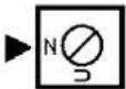
Check whether the actuator is in the safety position required by the process. (Does the actuator open or close with spring force?) The mounting side is selected from the table below in accordance with the direction of action and the required direction of movement of the spindle for an increasing input signal.
| Actuator closes with spring force | Changeover plate setting | Actuator opens with spring force | Changeover plate setting |
 |  |  |  |
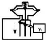 |  | 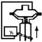 |  |
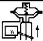
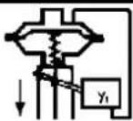
The arrow indicates the direction of movement of the spindle at increasing input signal.
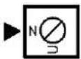
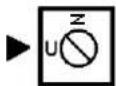
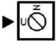
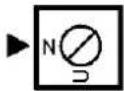
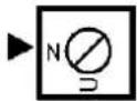
The direction of action of the input signal can be set on the changeover plate 13 :
N = Normal direction of action (increasing input signal produces increasing control pressure to the actuator)
U = Reverse direction of action (increasing input signal produces decreasing control pressure to the actuator)
Double-acting diaphragm actuators
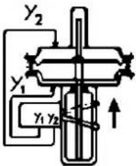
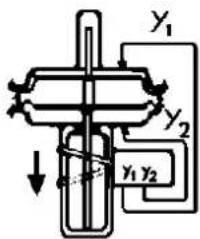
For double-acting positioners the changeover plate 13 always stays in the "N" setting. The assignment of the input signal to the direction of movement of the actuator spindle is determined by the selection of the mounting side of the positioner and the piping of the positioner outputs to the actuator:
| Changeover plate setting | Changeover plate setting | ||
 |  |  |  |
natural_image
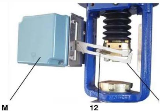
Mechanical assembly diagram showing a blue box labeled M and a blue spring with labeled parts 12 (no text or symbols beyond labels)Ensure that the feedback lever 11 is horizontal at 50 % stroke.
Fasten housing cover in such a way that air vent of attached device faces downwards (see Mark 'M').
11 Life Is On
Foxboro™
by Schneider Electric
2 MOUNTING TO ROTARY ACTUATORS
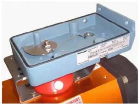
a) Remove the transparent cover plate from the housing of the attachment kit.
b) Mount the housing of the attachment kit on rotary actuator or armature; use mounting hardware supplied by the actuator manufacturer if necessary.
c) Move actuator into the desired starting position (rotation angle = 0°).
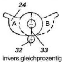
d) Mount cam 24 in accordance with the direction of rotation of the actuator.
The linear cam is fastened to the actuator drive shaft in such a manner that the distance x between the inside of the housing and the came amounts 2 mm, whereas in case of equal percentage cam the dimension x is approx. 17.5 mm.
In case of inverse equal percentage cam the dimension x is approx. 18 mm.
When employing equal percentage and the inverse equal percentage cams, the range spring (yellow) EW420493013 must be installed in the positioner.
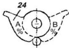
e) Fasten feedback lever 30 for the rotary actuator onto shaft 15 of positioner.
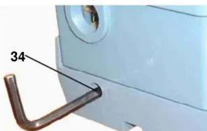
f) Mount positioner on housing of attachment kit. Attach spring 31 to feedback lever 30 and cam follower 32 against cam.
Screw positioner to housing of attachment kit. With the linear cam and the inverse equal percentage cam check whether mark 33 points to the center of the cam follower 32; adjust if necessary.
With the equal percentage cam check whether the cam follower lies directly ahead of the start of the cam lobe; adjust if necessary.
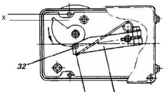
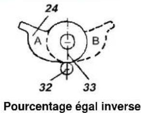
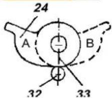
g) Final mounting of feedback lever on shaft of positioner is performed at a stroke of 0 %, i.e. a rotation angle of 0°. First loosen 5 mm A/F Allen screw of feedback lever 30 through hole 34, then press stroke factor lever 17 against stop screw 18 (see page 5) and tighten Allen screw firmly.
Note!
If actuator moves to an end position, the mounting position of cam does not coincide with the direction of rotation of the actuator. In this case install the cam 24 in the reverse position.
natural_image
Exterior view of a blue industrial control box with red LED indicator (no visible text or symbols)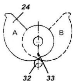
linear
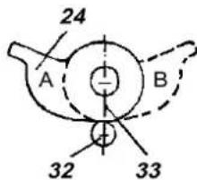
inverse equal percentage
equal percentage
A = Mounting position for actuator rotation ↓
B = Mounting position
for actuator
rotation ↓
31 30

natural_image
Close-up of a metallic tool interacting with a dark, smooth object on an orange surface (no text or symbols visible)3 PNEUMATIC CONNECTIONS
Air supply (s): 1,4 to 6 bar (but not more than the max. pressure of actuator), free of oil, dust and water!
4 Pneumatic input signal (w)
6 Internal thread G 1/8 for output II (y2) (only on double-acting positioners)
7 Internal thread G 1/8 for supply air
8 Internal thread G 1/8 for output I (y1)
4 ELECTRICAL CONNECTIONS OF OPTION
natural_image
Simple line drawing of a rectangular object with four circular indentations on its base (no text or symbols)4
8
7
6
Air supply according to ISO 8573-1
- Solid particle size and density class 2
- Oil rate class 3
Pressure dew point 10 K below ambient temperature
The safety requirements of the document EX EVE0001 as well as the requirements of the PSS EVE0101 and MI EVE0101 for the SRP981 must be observed
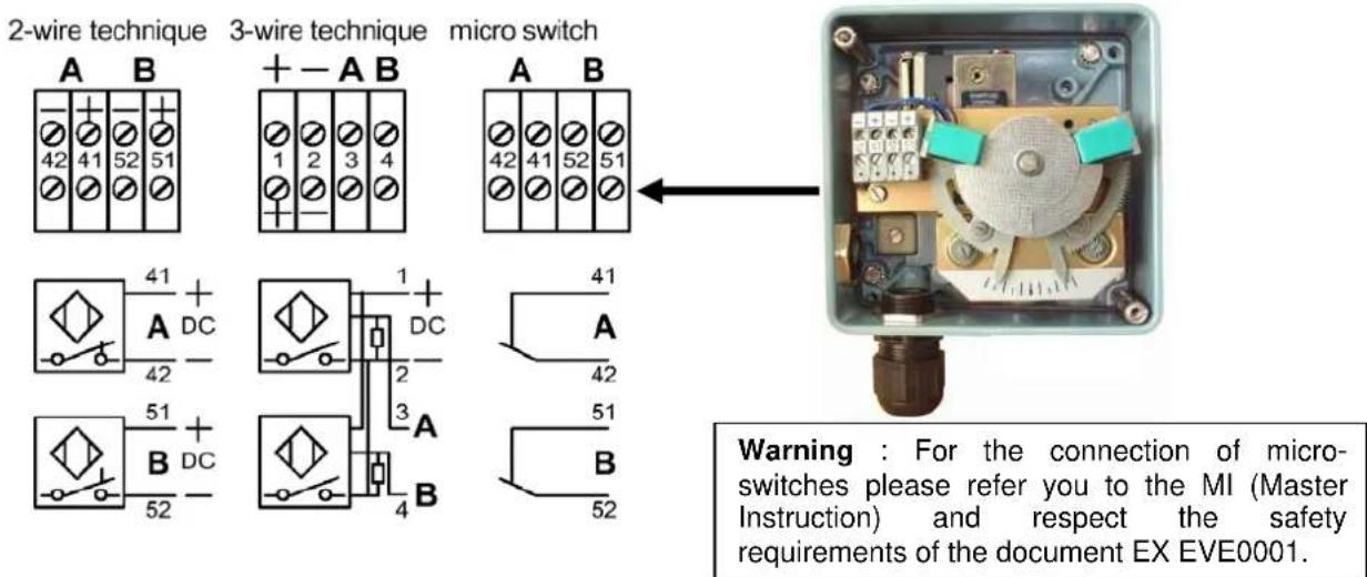
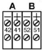
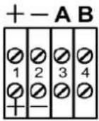
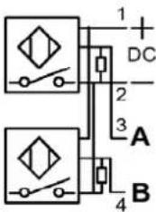
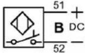
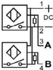
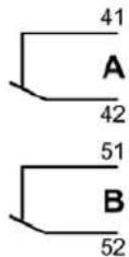
4.1 Option "Limit switch"
The limit switches is an accessory either installed in the factory or retrofit.
This unit can consist of either inductive slot type sensors or micro switches.
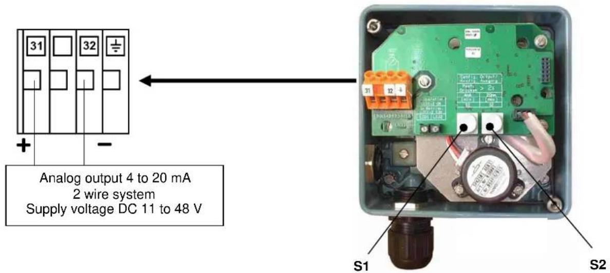
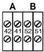
4.2 Option "Position Transmitter 4-20 mA"
The electrical position transmitter is an accessory either installed in the factory or retrofit. It converts the stroke or rotary movement of an actuator into an electrical standard signal 4-20 mA.
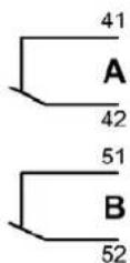
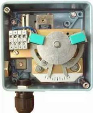
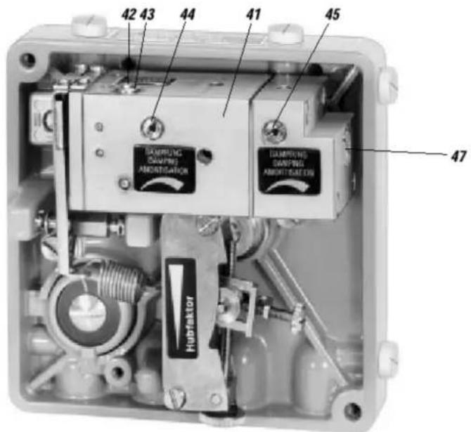
5 SETTINGS AND START UP
5.1 Setting of zero point and stroke on the positioner
(see page 5 for the reference of the number)
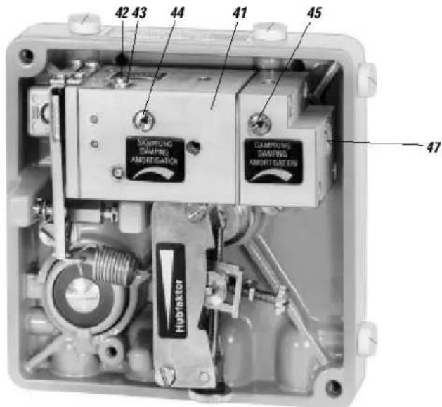
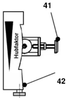
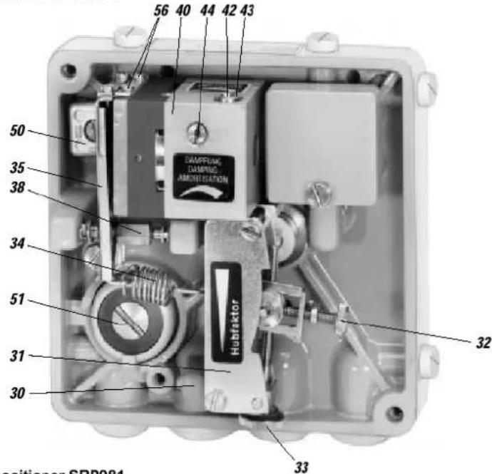
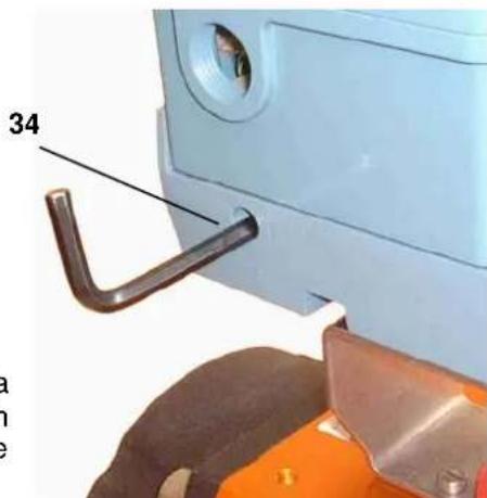
Before starting with the set-up push the flapper lever 40 several times alternately to the left and right in order to align the flappers correctly.
a) Set the minimum value of the input signal w (start of stroke).
b) Turn zero screw 41 until actuator just begins to move from its end position.
c) Set maximum value of the input signal w (end of stroke).
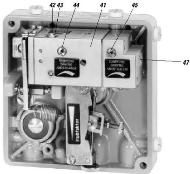
d) Turn the stroke factor screw 42 until actuator precisely reaches its end position:
Right turn: decrease of travel
Left turn: increase of travel
Repeat the operations (a to d) 2 or 3 times in order to insure an accurate positioning.
Note:
Changes of the gain will influence the settings of zero and span.
If the stroke cannot be adjusted with the installed spring, a suitable spring can be determined with the table on page 5.
5.2 Setting the damping
The air output capacity of the positioner can be reduced by means of the damping throttle 44. Double-acting positioners are equipped with a damping throttle 44 for correcting the variable y1 and a damping throttle 45 for correcting the variable y2. In its normal setting the damping throttle is approximately flush with the amplifier housing.
The air output capacity is reduced by a factor of approximately 2.5 when the damping throttle is turned completely.
5.3 Setting and Start Up of position transmitter 4-20 mA
Attachment and start-up of the unit to the actuator must be performed according MI EVE0101 A. At 50% stroke, the control lever must be horizontal.
The electronic connection of the position transmitter must be assured. Both LEDs are then light up.
Adjusting the start of the measuring range (4 mA)
a) Move the actuator to the starting position.
b) Press push button S1 „Config Output 4 mA“ longer than 2 seconds. During this time LED 1 lights up. After 2 seconds both LEDs are light up again, the value for 4mA is stored.
Adjusting the end of the measuring range (20 mA)
a) Move the actuator to the end position.
b) Press push button S2 „Config Output 20 mA“ longer than 2 seconds. During this time LED 2 lights up. After 2 seconds both LEDs are light up again, the value for 20 mA is stored.
Random adjustment of the current values at the end points
a) Move the actuator to the end position, where you want to adjust the current.
b) Press both buttons simultaneously for about 2 seconds. Then both LEDs are alternating flashing in a slow frequency.
c) With push button S1 „Config Output 4 mA“ the output current value can be decreased and with push button S2 „Config Output 20 mA“ the output current value can be increased. Pressing the buttons for a short moment results in a small change and pressing the button for a longer time results in a fast mode for a bigger change. The value of the current can be freely decreased between about 3.3 and increased up to 22.5 mA.
d) Without any additional manipulations of the push buttons the new value is automatically saved. After a few seconds, the device returns into the normal operating mode, indicated by both LEDs that are then light up again.
Trouble shooting of the position transmitter
The components of the position transmitter are under constant surveillance by the installed micro controller. Errors are detected and indicated when both LEDs are off or both LEDs are parallel flashing at a fast frequency.
In the event of a fatal error, e.g. potentiometer not connected, an output current of more than 24 mA will be shown in addition to the error indication given by the LEDs (fast flashing).
In this case check the following:
a) if the potentiometer is correctly connected to the electronic board.
b) if the potentiometer is within its working span.
When both LEDs are off, the supply voltage should be checked (minimum tension, polarity).
5.4 Spring range
Five different springs for the travel ranges are available for matching to the stroke and input signal range. In the following table the stroke range is given for a normal application (4-20 mA and with our standard feedback lever).
| Spring range Stroke range | in mm | Remarks | |
| Ident N° Colour | |||
| EW420493013 Yellow 8 - 34 | |||
| EW420494019 green 17 - 68 Built-in | |||
| EW502558017 - without - 28 - 105 | |||
| EW420496011 gray 40 - 158 | |||
| EW420495014 blue 55 - 200 | |||
5.5 Functional designation
Single acting positioner SRP981
Double acting positioner SRP981
Invensys Systems, Inc. 38 Neponset Street Foxboro, MA 02035 United States of America
schneider-electric.com
Global Customer Support Toll free: 1-866-746-6477 Global: 1-508-549-2424 Website: http://support.ips.invensys.com
Copyright 2010-2016 Invensys Systems, Inc. All rights reserved. Invensys, Foxboro, and I/A Series are trademarks of Invensys Limited, its subsidiaries, and affiliates. All other trademarks are the property of their respective owners.
natural_image
Close-up of a mechanical device with internal spring and housing (no visible text or symbols)M
by Schneider Electric
2 ANBAU AN SCHWENKANTRIEBE
natural_image
Exterior view of a light blue industrial control box with metallic components and red base (no visible text or symbols)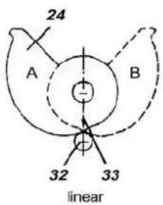
2-wire technique 3-wire technique micro switch
natural_image
Interior view of an industrial control box with visible wiring, switches, and components (no text or symbols)Single acting positioner SRP981

Double acting positioner SRP981
SRP981 POSITIONNEUR PNEUMATIQUE
natural_image
Mechanical assembly diagram showing a blue mechanical device with internal components and labeled parts M and 11 (no text or symbols beyond labels)12
by Schneider Electric
2 MONTAGE SUR SERVOMOTEURS ROTATIFS
natural_image
Exterior view of a light blue industrial control box with metallic components and a red warning light (no visible text or symbols)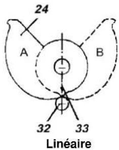
3 RACCORDEMENTS PNEUMATIQUES
natural_image
Simple line drawing of a rectangular device with four circular buttons at the base (no text or symbols)4
8
7
6
Air selon ISO 8573-1
natural_image
Interior view of an industrial control panel with visible components and wiring (no text or symbols)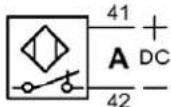
by Schneider Electric
Invensys Systems, Inc. 38 Neponset Street Foxboro, MA 02035 United States of America
schneider-electric.com
Global Customer Support Toll free: 1-866-746-6477 Global: 1-508-549-2424 Website: http://support.ips.invensys.com
Copyright 2010-2016 Invensys Systems, Inc. All rights reserved. Invensys, Foxboro, and I/A Series are trademarks of Invensys Limited, its subsidiaries, and affiliates. All other trademarks are the property of their respective owners.
DOKT 556 806 014 FD-QG-PO-007-FR
0316
SRP981 POSIZIONATORE PNEUMATICO
by Schneider Electric
2 MONTAGGIO SU ATTUATORI ROTATIVI
natural_image
Exterior view of a blue industrial control box with metallic components and orange base (no visible text or symbols)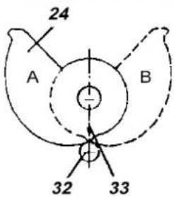
Lineare
di
Note!
natural_image
Simple line drawing of a rectangular object with four circular indentations on its side (no text or symbols)4 8 7 6
natural_image
Interior view of an industrial control box with visible circuitry and components (no text or symbols)Single acting positioner SRP981
Double acting positioner SRP981