
Desk Bike 1.0 - Exercise bike VirtuFit - Free user manual and instructions
Find the device manual for free Desk Bike 1.0 VirtuFit in PDF.

| Product type | Folding exercise bike |
| Brand | VirtuFit |
| Model | Desk Bike 1.0 |
| Usage | Indoor, home use |
| Maximum user weight | 110 kg |
| Console power supply | 4 AA 1.5V batteries (not included) |
| Display | Time, speed, distance, calories, odometer, heart rate |
| Heart rate sensor | Integrated on the handlebar |
| Resistance | Manually adjustable by button |
| Seat | Height adjustable (seat post with button) |
| Foldability | Yes, with locking pin |
| Pedals | Right (R) and left (L) detachable |
| Noise level | Quiet (pedaling noise possible) |
| Operating temperature | 10°C to 35°C |
| Storage temperature | 5°C to 45°C |
| Recommended safety clearance | 1 to 2 meters behind the device |
| Installation surface | Flat, stable, clean, avoid thick carpets |
| Daily maintenance | Clean and remove sweat after each use |
| Semi-annual maintenance | Check and tighten bolts, inspect moving parts |
| Cleaning | Soft cloth and mild detergent, avoid harsh chemicals |
| Repairability | Repairs by professional technician unless otherwise indicated |
Frequently Asked Questions - Desk Bike 1.0 VirtuFit
User questions about Desk Bike 1.0 VirtuFit
0 question about this device. Answer the ones you know or ask your own.
Ask a new question about this device
Download the instructions for your Exercise bike in PDF format for free! Find your manual Desk Bike 1.0 - VirtuFit and take your electronic device back in hand. On this page are published all the documents necessary for the use of your device. Desk Bike 1.0 by VirtuFit.
USER MANUAL Desk Bike 1.0 VirtuFit
natural_image
Technical line drawing of a mechanical device with a lever and bracket (no text or symbols)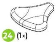
2 (1×)
natural_image
Simple line drawing of a curved pipe with two flanged ends and a green circle labeled '8 (1x)' at the top (no text or symbols on the pipe itself)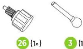
natural_image
Two mechanical components: a threaded bolt and a cylindrical rod, both shown with green circular labels (no text or symbols on the objects themselves)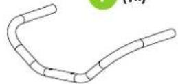
natural_image
Two identical illustrations of a waffle-shaped appliance with handles, each labeled with a green circle indicating a multiplier (1x), no text or symbols present.


STEP 01
STEP 02
STEP 03
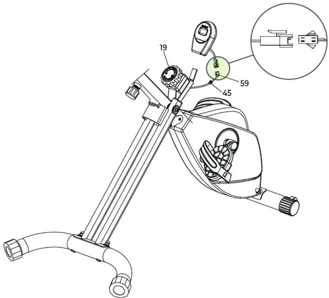
FIG. A

FIG. B
natural_image
Line drawing of a person bending forward with hands raised (no text or symbols)1
natural_image
Line drawing of a person sitting cross-legged, holding their head in thought (no text or symbols)2
natural_image
Line drawing of a person performing a seated stretch or exercise (no text or symbols)3
natural_image
Line drawing of a person in athletic attire performing a forward bend gesture (no text or symbols)4
natural_image
Line drawing of a person performing a stretching exercise with arms raised (no text or symbols)5
INDEX
| Safety instructions | 8 | ||
| Guarantee | 8 | ||
| Assembly instructions 8 | |||
| Adjusting | 9 | ||
| Folding instructions 9 | |||
| Maintenance | 10 | ||
| Troubleshooting | 10 | ||
| Console | 11 | ||
| Training guidelines | 11 | ||
SAFETY INSTRUCTIONS

WARNING!
Consult your doctor before you start exercising. This is particularly important for people with health problems. Please read all instructions before using the machine. VirtuFit assumes no responsibility for injury or property damage resulting from the use of this equipment. Please read this manual carefully before assembling and/or using the machine.
- Make sure that the machine is properly assembled and that all nuts and bolts are tight before using it.
- Do not wear loose clothing to avoid getting caught in moving parts.
• Install and use the unit on a solid, level surface.
• Always wear clean sports shoes when using the appliance. - Keep children and pets away from the appliance when in use.
- Maintain your balance when using the device.
- Do not place your fingers or other objects in the moving parts.
- Before exercising, consult your physician to determine the appropriate frequency, duration and intensity of exercise for your age and physical condition. Stop exercising immediately if you experience nausea, shortness of breath, fainting, headache, chest pain, tightness or any other discomfort.
-
Do not hold the machine by the seat when moving.
• This machine should only be used by one person at a time. -
This machine is designed for domestic use and the maximum user weight is 110 kg.
- Leave 1-2 metres of space behind the machine to avoid accidents.
- Place the machine on a clean, flat surface. Do not place it on a thick carpet, as this may hinder the ventilation of the machine. Do not place the machine outdoors or near water.
- Keep the storage area dry, clean and level to prevent damage. Do not use the device for any purpose other than training.
- Use the device only in an environment where the ambient temperature is between 10^ and 35^ . Store the device only in an environment where the temperature is between 5^ and 45^ .
GUARANTEE
Warranty claims are excluded if the cause of the defect is the result of:
- Maintenance and repair work not carried out by an official dealer. Provided otherwise specified by the supplier.
- Improper use, negligence and/or poor maintenance.
- Failure to maintain the appliance in accordance with the manufacturer's instructions.
ASSEMBLY INSTRUCTIONS (STEP 01-03)
Missing parts: If any parts are missing from the packaging, carefully check the polystyrene foam and the appliance itself. Some parts (bolts, screws, etc.) are already attached to the unit.
Error message: Make sure that all cables are carefully attached. The aluminium feet of the console are very sensitive and must be kept straight. If the console gives an error message after the machine has been mounted, the aluminium feet of the console may be bent. Straightening the aluminium feet may make the error message disappear.
Hex head bolts: Make sure that the hex head spanner is pushed into the bolt before applying force. This will prevent the head of the socket bolt from turning.
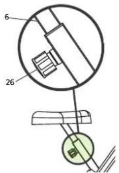
ADJUSTING
Saddle
In order to train effectively, it is advisable to adjust the saddle to the correct height. When pedalling, your knees should be slightly bent when the pedals are in the down position.
To adjust the saddle to the vertical position, follow the steps below:
- Loosen the knob on the seat post and pull the knob towards you.
- Move the seat post up or down until the saddle is in the desired position and release the knob.
- Move the seat post slightly up or down to ensure that the knob is in one of the adjustment holes.
- Tighten the knob on the seat post.
Waterpass
- For stability and safety reasons, the folding exercise bike has a welded frame. If assembled correctly at one time, the exercise bike will not require any further adjustment.
• Always make sure the folding exercise bike is placed on a stable surface. If in doubt, a rubber mat can be placed underneath the exercise bike to improve the grip on the floor. If the folding exercise bike requires adjustment, simply rotate the adjustable ends (27) on either side of the rear frame to compensate the exercise bike for an uneven surface.
Resistance knob
To ensure a smooth and efficient pedaling motion, the resistance is adjusted at the factory during production.
Tension adjustment with the resistance knob
The tension can be adjusted to different resistance levels by turning the resistance knob (19).
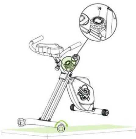
NOTE! It is recommended to start training at a level that suits your own needs. Remember to start slow and gentle and work your way up to the level that suits you.
FOLDING INSTRUCTIONS
NOTE! Store the Folding Exercise Bike in a dry place, out of reach of children, as shown in the diagram. Make sure the folding exercise bike is stable and secure to prevent it from falling on pets or children.
1
2
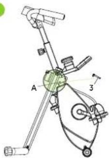
Folding (1)
The locking pin (3) can be used to fold the exercise bike. To fold the folding exercise bike, place the locking pin (3) in position A.
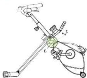
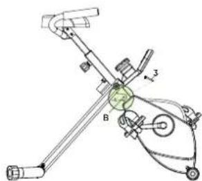
Folding (2)
The locking pin (3) can be used to unfold the folding exercise bike. When the folding exercise bike is to be used, place the locking pin (3) in position B.
MAINTENANCE
Safe and efficient use can only be achieved if the appliance is properly installed and maintained. It is your responsibility to ensure that the appliance is maintained regularly. Parts that have been used and/or damaged must be replaced before the appliance is used again. The appliance should only be used and stored indoors. Long-term exposure to weather and temperature/humidity changes can have a serious impact on the electrical components and moving parts of the unit. Always unplug the power cord from the unit before cleaning or servicing it.
Daily maintenance
- Clean and remove sweat and moisture after each use.
- Check that the unit is free of dust and dirt.
- Do not use aggressive cleaning agents and keep the device away from moisture.
Semi-annual maintenance
- Inspect all bolts and nuts connected to the moving parts of the unit. Tighten bolts and nuts as necessary and appropriate.
- Check the mobility of moving parts and components of the unit.
We recommend the following:
- Clean the unit after use.
- Use a dry cloth to clean the control panel and the areas around the on/off switch.
- Use a soft, clean cloth and detergent to remove stubborn marks and dirt from the unit.
- Store the unit in a safe, dry place away from heat and water.
CAUTION!
· Repairs must be carried out by a professional technician, unless otherwise specified by the supplier or manufacturer.
Cleaning
General cleaning of the unit will extend its life. Keep the appliance clean by dusting it regularly.
Regular maintenance will prolong the life of your appliance and prevent injuries!
CAUTION! Wear clean shoes to reduce the risk of soiling the
machine. At least once a year, remove the cover to remove dust.
Battery
AA BATTERIES
The display uses AA batteries, which are replaceable on the back of the display. The batteries must be inserted correctly.
If the screen is unreadable or only parts of the image work, proceed as follows:
- Remove the batteries and wait 15 seconds.
- Replace the batteries correctly.
Tips on using the battery
- Remove the batteries from the screen when they are empty or when the camera will not be used for a long period of time.
- Do not recharge, disassemble or dispose of batteries in fire.
- Pay close attention to the + and - when inserting the batteries. When replacing batteries, it is recommended to replace all batteries, do not mix old and new batteries.
- It is recommended to use alkaline batteries, they have a longer life than normal batteries.
- Batteries should be replaced when the display loses brightness or stops showing.
Battery replacement
- If the display is not accurate, it is recommended to replace the batteries.
- Use 4 x 1.5 AA batteries for power.
TROUBLESHOOTING
The display does not show any values: Check that the sensor and console cables are properly attached and undamaged. Replace the console batteries. If this does not solve the problem, contact the supplier.
Exercise bike squeaks: Check that all bolts and nuts are tight. If necessary.
Ticking noise when pedalling: This may be caused by one of the pedals. Remove the pedal(s) and mount it (them) correctly on the unit. Tighten the pedal(s) firmly. If this does not solve the problem, contact the supplier.
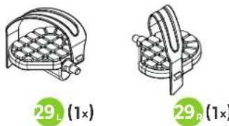
NOTE! The "R" (right) pedal must be mounted clockwise and the "L" (left) pedal must be mounted counter-clockwise.
Console does not work: If there is no signal when pedalling, check that the cable is correctly connected. If this does not solve the problem, contact the supplier.
CONSOLE (FIG. A)
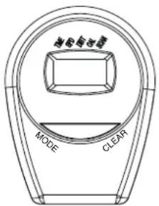
- TIME Press the MODE button until the TIME function is selected. The total cycle time from start to finish is displayed.
- SPEED Press the MODE button until SPEED is selected. The speed is displayed when you start the exercise.
- CALORIES Press the MODE button until CALORIES is selected. The total number of calories from the beginning to the end of the exercise is displayed.
- DISTANCE Press the MODE button until DISTANCE is selected. The distance of each exercise is displayed when you start exercising.
- ODO The distance is automatically added when you start the exercise.
- PULSE Press the MODE button until PULSE is selected. Keep your hands on the sensor for 3 seconds to display your heart rate.
Monitor
How does the monitor work?
- When the monitor is turned on (press and hold the MODE, RESET button for 3 seconds), the LCD screen will display each segment and beep for one second. Then go to SCAN.
- If a signal is sent to the monitor, the TMR, DST and CAL values will be added together.
- If no signal is sent to the monitor for 4 minutes, the monitor will automatically turn off.
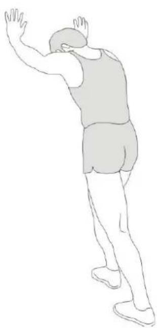
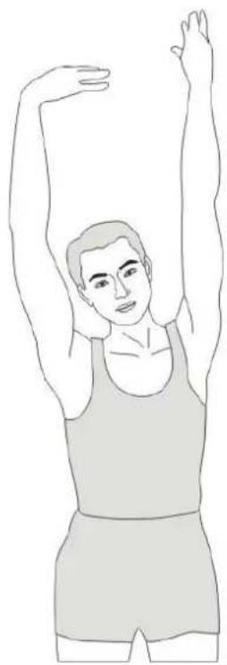
TRAINING GUIDELINES (FIG. B, 1-5)
A successful training program includes a warm-up, the actual training and a cool-down. Perform the complete training program at least twice, but preferably three times a week and keep a rest day between
training sessions. After a few months, the intensity of the training can be increased, for example to four or five times a week.
The warm-up
The purpose of a warm-up is to prepare the body for training and to reduce the risk of injury. Warm up your body for two to five minutes before starting a cardio or strength training session. Do exercises that increase the heart rate and warm up the working muscles. Examples of this type of activity are running, jogging, jumping jacks, skipping and running in place.
Stretching
Stretching while the muscles are warm is very important after a good warm-up and cool-down. It reduces the risk of injury. Stretching exercises should be held for 15-30 seconds. Here are some examples of stretching exercises:
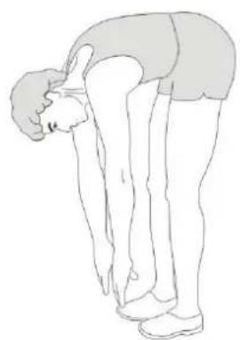
- Toe touch (Fig. B-1)
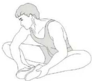
• Inner thight stretch (Fig. B-2)
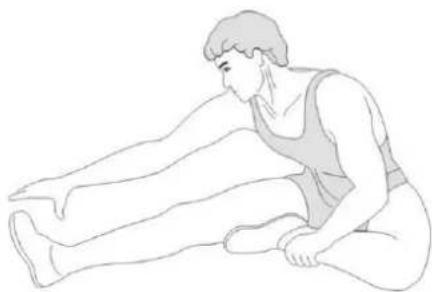
• Hamstring stretch (Fig. B-3) - Achilles stretch (Fig. B-4)
- Side stretch (Fig. B-5)
Cooling down
The purpose of the cool-down is to return the body to its (near) normal resting position at the end of the workout. A good cool-down slowly reduces your heart rate and promotes recovery.
INHOUD
natural_image
Line drawing of a stationary exercise bike with labeled components and an inset showing gear assembly (no text or symbols present)natural_image
Line drawing of a stationary exercise bike with labeled components and an inset showing gear assembly (no text or symbols present)2
FALTEN (1)
natural_image
Line drawing of a stationary exercise machine with labeled components and a magnified inset showing internal parts (no text or symbols present)DESCRIPTION QTY.
| 1 | Handlebar | 1 |
| 2 | Rear frame | 1 |
| 3 | Locking pin | 1 |
| 4 | Handle grip foam | 2 |
| 5 | Oval line plug | 3 |
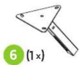
| 6 | Saddle support | 1 |
| 7 | Main frame | 1 |
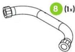
| 8 | Rear stabilizer | 1 |
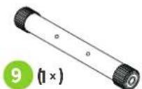
| 9 | Front stabilizer 1 | |
| 10 | Crank (R & L) | 2 |
| 11 | Main shaft | 1 |
| 12 | Lower drive wheel shaft | 1 |
| 13 | Magnetic bracket | 1 |
| 14 | Round steel | 2 |
| 15 | Oval pipe plug 20*40 | 1 |
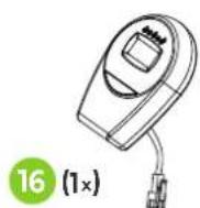
| 16 | Console | 1 |
| 17 | Plastic fine adjustment seat | 1 |
| 18 | Chain cover (U) | 1 |
| 19 | Tension Control Knob | 1 |
| 20 | EVA sticker | 1 |
| 21 | Screw M6 | 2 |
| 22 | Cross head screw M6 | 3 |
| 23 | Gear piece 2 | |
| 24 | Saddle | 1 |
| 25 | Saddle stem insert | 1 |
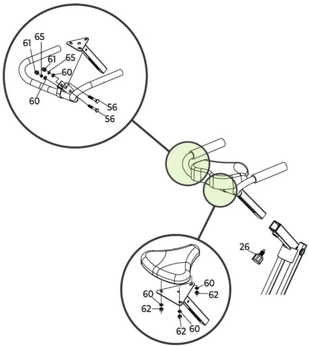
| 26 | Seat adjustment knob | 1 |
| 27 | Adjustable hex and cap | 2 |
| 28 | End cap | 2 |
| 29 | Pedal (R & L) | 2 |
| 30 | Chain cover (R & L) | 2 |
| 31 | Pulley brush | 2 |
| 32 | Flywheel | 1 |
| 33 | Pulley bracket | 1 |
| 34 | Lower drive wheel | 1 |
| 35 | Upper drive wheel shaft | 1 |
| 36 | Upper drive wheel | 1 |
| 37 | Sensor bracket 1 | |
| 38 | Magnet | 6 |
DESCRIPTION QTY.
| 39 | Crank guard trim 2 | |
| 40 | Pulley 4 | |
| 41 | Waved washer 5 | |
| 42 | Spring washer 4 | |
| 43 | Self-tapping screw M4*20 3 | |
| 44 | Screw M10 4 | |
| 45 | Round wire plug 1 | |
| 46 | Screw M5*50 1 | |
| 47 | Drive belt 230J 1 | |
| 48 | Drive belt 230J | 1 |
| 49 | Spring | 1 |
| 50 | Allen bolt M8*20 2 | |
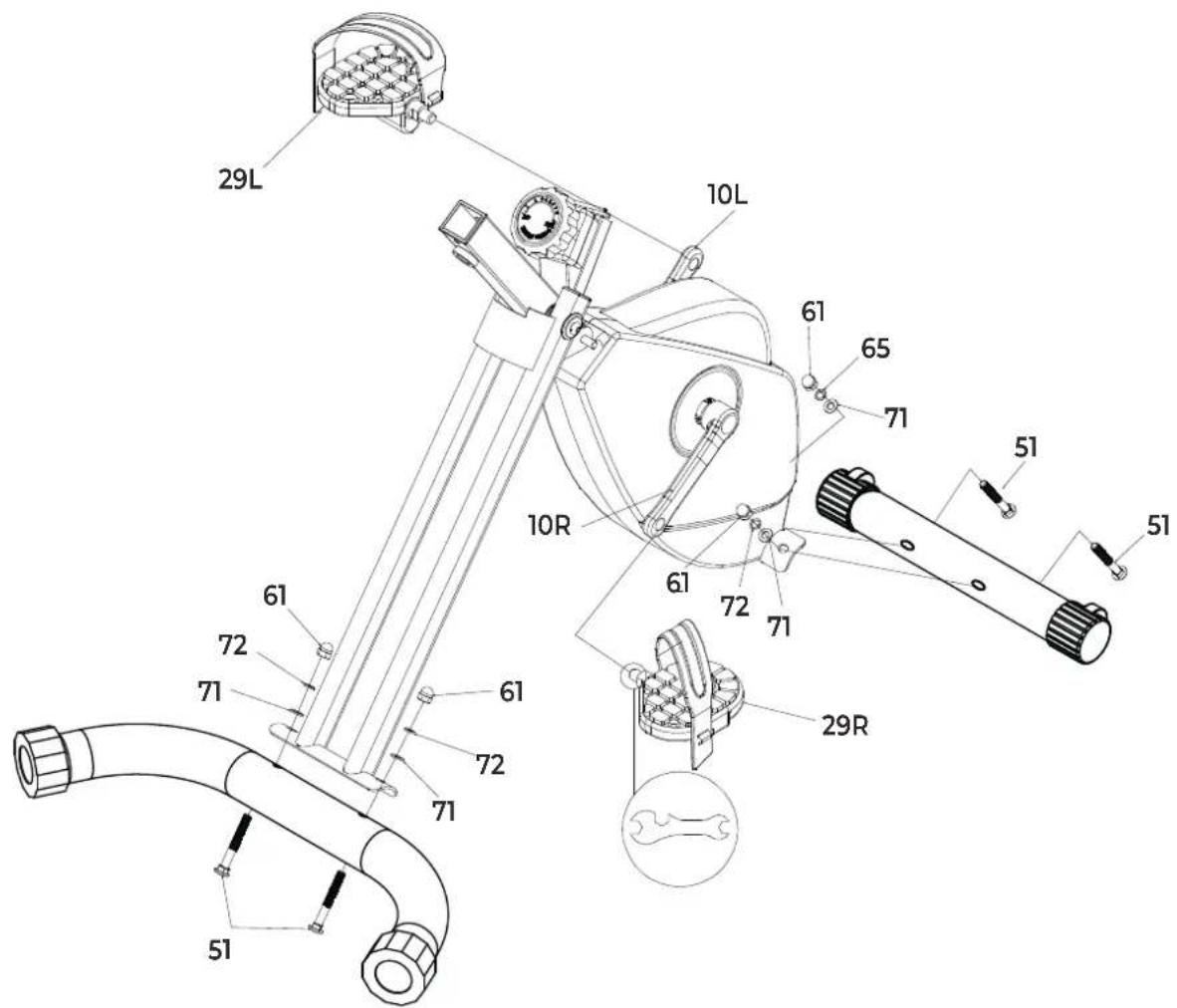
| 51 | Carriage bolt M8*65 | 4 |
| 52 | Screw M6*40 | 2 |
| 53 | Screw M6*15 | 6 |
| 54 | Self-tapping screw M4*20 | 4 |
| 55 | Nut M10 | 2 |
| 56 | Carriage bolt M8*45 | 2 |
| 57 | Round pipe plug ☐22 | 2 |
| 58 | Flat washer | 1 |
| 59 | Sensor wire | 1 |
| 60 | Flat washer M8 | 6 |
| 61 | Dome nut M8 | 6 |
| 62 | Nylon locknut M8 | 3 |
| 63 | Flat washer | 2 |
| 64 | Outer brush | 4 |
| 65 | Spring washer M8 | 7 |
| 66 | Lock ring | 1 |
| 67 | Bearing | 1 |
| 68 | Flat washer | 1 |
| 69 | Nylon locknut M10 | 1 |
| 70 | Pulley | 2 |
| 71 | Curved washer M8 | 4 |
virtufit


- SAFETY INSTRUCTIONS
- WARNING!
- GUARANTEE
- ASSEMBLY INSTRUCTIONS (STEP 01-03)
- ADJUSTING
- Saddle
- To adjust the saddle to the vertical position, follow the steps below:
- Waterpass
- Resistance knob
- Tension adjustment with the resistance knob
- FOLDING INSTRUCTIONS
- Folding (1)
- Folding (2)
- MAINTENANCE
- Daily maintenance
- Semi-annual maintenance
- We recommend the following:
- CAUTION!
- Cleaning
- Battery
- AA BATTERIES
- If the screen is unreadable or only parts of the image work, proceed as follows:
- Tips on using the battery
- Battery replacement
- TROUBLESHOOTING
- CONSOLE (FIG. A)
- Monitor
- How does the monitor work?
- TRAINING GUIDELINES (FIG. B, 1-5)
- The warm-up
- Stretching
- Cooling down
- INHOUD
- FALTEN (1)
- DESCRIPTION QTY.
- virtufit
Brand : VirtuFit
Model : Desk Bike 1.0
Category : Exercise bike