Specialista ST9612GI MS - Cooker Glem Gas - Free user manual and instructions
Find the device manual for free Specialista ST9612GI MS Glem Gas in PDF.

User questions about Specialista ST9612GI MS Glem Gas
0 question about this device. Answer the ones you know or ask your own.
Ask a new question about this device
Download the instructions for your Cooker in PDF format for free! Find your manual Specialista ST9612GI MS - Glem Gas and take your electronic device back in hand. On this page are published all the documents necessary for the use of your device. Specialista ST9612GI MS by Glem Gas.
USER MANUAL Specialista ST9612GI MS Glem Gas
p.2 INSTRUCTIONS BOOKLET
p.22 NOTICE D'UTILISATION

43 صفحة
natural_image
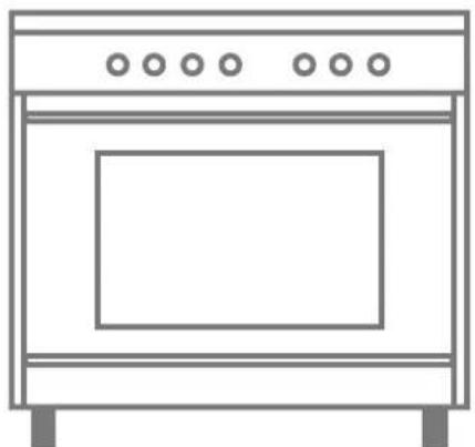
Line drawing of a simple kitchen oven with five windows (no text or symbols)Cookers
We would like to thank you for purchasing one of our products, we are confident it will fulfil your needs. We would also like to invite you to read this booklet carefully and keep it safe, as it contains important information and useful tips for your new cooker optimal use, in complete safety.
This appliance is in conformity in force:
- 2014/35/EC Low Voltage (Directive)
- 2014/30/EC Electromagnetic Compatibility (Directive)
- 2016/426/EC Gas Appliance (Directive)
- 1935/2004/EC Materials intended to come into contact with food (Regulation)
- 2011/65/EC Restriction of the use of certain hazardous substances in electrical and electronic equipment (Directive)
- 2010/30/EC Energy labelling of household electric ovens (Directive)
TABLE OF CONTENTS
03 General warnings
05 Your product
05 Use
Hob
Oven
Programmers and minute minders
Cooking suggestions
09 Cleaning
10 Maintenance
11 Instructions for the installer
Product handling
Installation
Adaptation to the different types of gas
15 Technical assistance
15 Product and packaging disposal
16 Cleaning and maintenance stainless steel
18 Technical data
20 Cooking and grilling tables
GENERAL WARNINGS
This appliance is only designed and built for household use. Any other use, such ad heating, for example, is considered improper, and therefore highly dangerous.
Keep children away with under the age of 8 years, if not under the constant supervision of an adult.
Children and people with reduced physical, mental or sensory abilities and/or with lack of adequate knowledge of the use and dangers that the equipment can entail, are forbidden to use this appliance unless they are under the constant supervision of a responsible adult.
Children must not play with or near the appliance, whether it is in operation or not. Please do not allow children to clean the appliance.
If the appliance has a fault and/or is not working properly, please close the gas line, disconnect the appliance from the power mains, and do not attempt to service it by yourself. Contact your nearest authorized assistance centre directly (see the “technical assistance” section herein).
The surface temperatures of every part must strictly comply with the regulations in force. This does not mean that some metal parts will not burn during or after its use. Accordingly, please use with due care.
The cooker cannot be installed without feet;
The Company will not be held liable in case of failure to observe the information provided herein.
The Company reserves the right to change product specifications maintaining safety and functionality.
The alcohol vapours inside the hot cooking compartment may catch fire. Do not cook food containing large quantities of beverages with a high alcohol content.
Only use small quantities of beverages with a high alcohol content. Open the door of the appliance carefully.
CAUTION

Some parts of the cooker are protected by a special film. Take it out before operating the appliance and use lukewarm soapy water to remove any sticky residue.

Preventing accidents in the home
Do not leave the appliance unattended when cooking with fats or oil: it may cause a fire.
Do not leave objects near the cooking surfaces.
If glass ceramic hobs crack, turn the appliance off to prevent possible electric shock.
NEVER try to put out a flame/fire with water; rather, turn the appliance off and cover the flame with a lid or flame-proof blanket.

Prevent pots from protruding from the hob edges during use. It is also advisable to use containers with an intact, flat base.

During use the appliance overheats. Children must be kept away from the appliance. Be careful to avoid touching the heating elements inside the oven.

The accessible parts can be hot when the grill is used, therefore children must be kept away.

Do not use jets of steam to clean the appliance. Steam could reach the electrical parts, damaging them and causing short circuits. Do not use cleaning products that contain chlorine, ammonia or bleach on parts made of steelor superficially treated with metal finishes (for example anodizing, nickel plating, chrome plating).

It is essential that all installation, adjustment and technical maintenance operations are carried out by qualified personnel only. The appliance must be installed in compliance with the regulations in force in the country of use.

Prior to every maintenance operation it is necessary to unplug the appliance from the power socket and wait for it to cool down completely.

To prevent accidental tipping of the appliance to install a stabilizing device, as shown on page 12 in the installation section.

The appliance is designed to operate with different types of gas; each type of gas requires specific injectors and adjustments. To make any change, it is always necessary to disconnect the appliance from the power mains, and temporarily cut off the gas supply from the mains.

If your cooker has a glass lid, make sure it is lifted open before turning on the burners, during use and the subsequent cooling phase. Failure to do so may cause breakage of the glass.

Do not use abrasive products or sharp metal spatulas to clean the oven door glass as this may scratch the surface, causing the glass to shatter.

Remove any liquids that may have overflown onto the lid before opening it. Let the surface of the hob cool down before closing the lid.

The first time you use the oven, ake out all of the accessories and supplied materials placed inside of it, turn it on and let it run idle for at least one hour at the highest temperature, with the door closed (but not using the grill). Then, switch it off, open the oven door and ventilate the room. Any odour you can smell is from the evaporation of the sealing and protective substances inside the oven.

The appliance is not conceived to operate with an external timer or remote control system.

The use of a gas appliance produces heat and moisture in the room where it has been installed. Please ensure good ventilation of the room keeping open the orifices of natural ventilation or installing a mechanical ventilation device (extraction hood with exhaust duct).

During cooking do not cover the bottom of the oven or hob with aluminum foil.

Foods must be cooked under constant supervision. Even brief cooking must be constantly supervised.

Do not install the appliance on a raised base and/or platform.

Do not install the appliance behind decorative doors in order to prevent excessive heating.
YOUR PRODUCT
Given the wide range of products available on the market, this booklet contains information about several models, and it is therefore possible that not all of the information contained here in refers to your appliance or its accessories. We are nevertheless at your disposition for any clarification you may require.
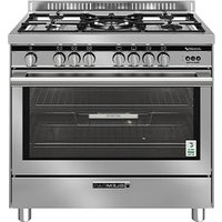
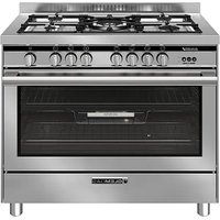
Your cooker consists of the following main parts:
- hob: flat top part where the pan supports (supports for the pots), the gas burners, electric plates or the glass-ceramic areas, depending on the size and the model of your cooker are located.
• control panel: cooker control devices zone (i.e. knobs and switches). - oven door
HOW TO IDENTIFY THE SYMBOLS ON THE CONTROL PANEL
| SYMBOL MEANING | |
| Burner / front left area | |
| Burner / rear left area | |
| Central burner | |
| Burner / front right area | |
| Burner / rear right area | |
| Burner / left area | |
| Oven temperature control (°C) | |
| Timer / minute minder | |
| SYMBOL MEANING | |
| Multi-function electric oven features | |
| Oven thermostat | |
| Gas oven burner | |
| Grill burner | |
| Light button | |
| Ignition button (spark) | |
| Ventilated gas button (Multichef) | |
| These two pilot lights indicate that the electric oven is on and/or that the oven is heating up. | |
USE
HOB

USING THE HOB
If your cooker has a glass lid, make sure it is lifted open before turning on the burners, during use and the subsequent cooling phase. Failure to do so may cause the breakage of the glass.
Place a lit match near the burner (or a spark or a flame generator), press and turn the corresponding knob counter-clockwise to the MAX position. The hob can be equipped with electrical ignition activated through a separate button or by pressing the knob. When it is lit, hold the knob down for approximately 10 seconds, then release it and adjust flame intensity, being careful to position the knob in the area between maximum and minimum (included) and never between maximum and zero to prevent turning it off unexpectedly. The burner may go out when you release the knob: this means that the thermocouple is not hot enough. If it does not ignite within 15 seconds, wait 1 minute before trying again. If your model does not have a gas safety valve (copper-coloured thermocouple near the burner), please check that, at regular intervals, the flame does not go out due to possible liquid overflowing from the pots during cooking.
USE OF ELECTRIC PLATES
The electrical plates are switched on by turning the knob clockwise, at a value between 0 and 4.
The higher the number, the greater the applied electrical power. By turning a plate on for the first time or after a long period of inactivity, it is advisable to make it run idle without cooking on it, on the "minimum heating" position (position 1) for at least 15 minutes, so as to eliminate any humidity that the insulation may have absorbed. To optimize the use of electric plates, use flat-bottomed pots and avoid using pots with diameters smaller than the plates.
USING GLASS-CERAMIC HOBS (HIGHLIGHT)
Please refer to the booklet supplied with the appliance.

PREVENTING HOME ACCIDENTS
Do not leave the appliance unattended when cooking with fats or oil: it may cause a fire.
Do not leave objects near the cooking surfaces.
If glass ceramic hobs crack, turn the appliance off to prevent possible electric shock.
PRACTICAL TIPS FOR USING THE HOB
For best use of the burners with minimum gas consumption, it is advisable to use flat-bottomed pots with lids, and a suitable size for the burner. The table below provides the pot diameters for each burner, from the smallest to the largest.
| Type (burner size in cm) Pot size (cm) |
| Auxiliary burner (A) ∅ 5 ∅ 10 - 14** |
| Semi-rapid Burner (S) ∅ 7.5 ∅ 16 - 20 |
| Rapid Burner (R) ∅ 10 ∅ 20 - 24 |
| Triple Crown Burner (TC) ∅ 13 ∅ 24 - 28 |
| Fish Burner (FB) 6x23,5 max 14x35 |
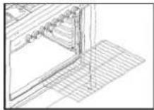
** The reduction grill, FOR models that include it, must only be used for the auxiliary burner when cooking with pots with a diameter less than 12 cm.
| Type (screen-printing area size in cm) Pot size (cm) | |
| Electrical plate ∅ 14.5 | ∅ ≧14,5 |
| Electrical plate ∅ 18 ∅ 18 | ≥ |
| Glass-ceramic area (highlight) ∅ 14.5 | ∅ ≧14.5 |
| Extendible glass-ceramic area (highlight) ∅ 12 - 21 | ∅ ≧12 - 21 |
| Glass-ceramic area (highlight) ∅ 21 | ∅ ≧21 |
| Extendible glass-ceramic area (highlight) ∅ 17 - 26.5 | ∅ ≧17 - 26.5 |
OVEN
TURNING THE OVEN ON
The first time you use the oven, take out all of the accessories and supplied materials placed inside it, turn it on and let it run idle for at least one hour at the highest temperature, with the door closed (but not using the grill). Then, switch it off, open the oven door and ventilate the room. Any odour you can smell is from the evaporation of the sealing and protective substances inside the oven.
COOKER WITH GAS OVEN AND ELECTRIC GRILL
The gas oven is equipped with a heating element (oven burner) located under the base of the oven and with a top heating element (grill). Some models also have a rear fan, which can be switched on and off with a key, and is used to evenly distribute heat during use. To check the oven, it is necessary to use a knob and 1 or 2 keys (☐/☐*).
The oven burner must always be lit with the oven door fully open. Press and turn the oven knob counter-clockwise to the MAX position. Holding the knob down, bring a lit match (or a spark or a flame generator) close to the hole on the base of the oven. Keep the knob pressed down for approximately 10 seconds, then release it and adjust to the required temperature. If the burner does not ignite within 15 seconds, wait 1 minute before trying again. In some models the burner can be equipped with ignition activated with a separate button or by pressing the knob itself. When it is lit, keep holding the knob down for approximately 15 seconds. The burner may go out when you release the knob: this means that the thermocouple is not hot enough. Wait at least 1 minute and repeat the operation holding the knob down longer.
ELECTRIC GRILL
The Grill feature is switched on and off from its key. In cookers with an accessory to protect the knobs (glazed black heat insulator) grilling must be done with the oven door partially open. Before starting the grill, assemble the heat insulator on the slots located on both sides of the frontal part, between the control panel and the oven itself. If your cooker does not have this accessory, it means that grilling must be done with the door closed.
This type of cooker has a burner located under the base of the oven and a grill burner on the ceiling of the oven.
Generally only one knob is used to control the oven. Some models have two separate knobs, one for each burner, allowing the two burners inside the oven to be used at the same time. This particular option is useful for cooking large quantities of food. Holding the knob down, bring a lit match (or a spark or a flamegenerator) close to the hole on the base of the oven. Keep the knob pressed down for approximately 10 seconds, then release it and adjust to the required temperature. Close the ove door and wait about 15 minutes to preheat the cavity, some models also have a rear fan which is used to evenly distribute heat during oven use. If you need to carry out cooking with forced air, insert its control after that the oven has been already preheated.
GAS OVEN
The oven burner must always be lit with the oven door fully open and the cavity empty. Press and turn the oven knob counterclockwise to the MAX position. Some models also have a rear fan which is used to evenly distribute heat during oven use. If you need to carry out cooking with forced air, insert its control after that the oven has been already preheated.
The grill burner must always be lit with the oven door fully open and the cavity empty. Press and turn its knob counter-clockwise to the MAX position. Holding the knob down, bring a lit match (or a spark or a flamegenerator) close to the grill burner. Keep the knob pressed down for approximately 10 seconds, then release it. Close the oven door and wait few minutes to preheat the cavity, after that put foods inside the oven on the desired level.
The oven burner must always be lit with the oven door fully open and the cavity empty. Press and turn the oven knob counterclockwise to the MAX position. Holding the knob down, bring a lit match (or a spark or a flamegenerator) close to the hole on the base of the oven. Keep the knob pressed down for approximately 10 seconds then release it. Closed the oven door and wait about 15 minutes to preheat the cavity. After that, set your cooking temperature, put foods inside the oven on the desired level and ignite the gas grill.

WARNING: IT'S ADVISABLE TO UTILIZE THE CLOSED DOOR GRILLING FUNCTION FOR MAX 25 MINUTES, TO AVOID AN EXCESSIVE OVERHEATING OF THE EXTERNAL SURFACES.
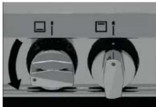
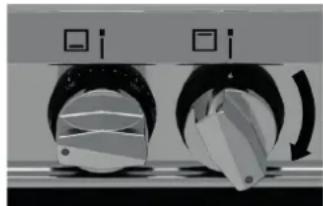
USE THE GAS OVEN WHIT THE GAS GRILL TOGETHER FOLLOWING THE INSTRUCTIONS BELOW:
1) SET THE GAS OVEN TEMPERATURE ON THE DESIRED VALUE (see picture A);
natural_image
Diagram of a rotary switch mechanism with two circular components and directional arrows (no text or symbols)Picture A
2) SET THE GRILL GAS TEMPERATURE AT THE MINIMUM (see picture B);
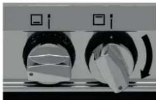
natural_image
Close-up of two circular mechanical components with arrows indicating rotation or adjustment (no visible text or symbols)Picture B
COOKER WITH ELECTRIC OVEN
There are two types of electric ovens in our range: static (no fan) and multifunction. Static ovens only have one control knob which manages the features and internal temperature, while multifunction ovens have two knobs: one to select the features and another to manage the temperature.
ELECTRIC OVEN WITH 1 KNOB (STATIC - NO FAN) TO CONTROL THE OVEN
Turn the knob □ clockwise and set the required temperature. Both lights on the control panel will turn on, indicating that the oven is on and is heating up. When it reaches the required temperature, the light indicator will switch off.
In these models the Grill is switched on by turning the knob clockwise by three clicks. The grill (heating element) must be used with the oven door partially open. In these cases it is essential that you apply a device to protect the knobs (glazed black heat insulator) which is part of the standard supply of the cooker (it will be inside the oven). With the door open, the device must be inserted into the slots on both side of the front of the oven, between the control panel and the oven itself.
Attention: when the grill is in use, the accessible parts may reach high temperatures.
MULTIFUNCTION OVEN
Multifunction electric ovens are controlled by a feature selector (knob) associated to a thermostat that allows you to choose the required temperature. Depending on the oven model, it will have various cooking features (see the cooking features table to identify symbol and use). Select the desired feature and temperature. If the cooker does not have any heat insulator, this means that grilling is carried out with the door closed and it is not possible to set temperatures above 200^ C.
For immediate access to the cooking features in ovens with a programmer (manual, analogue or electronic), always make sure the programmer / timer is in "manual" mode.
TURNSPIT
The turnspit can be switched on from a manual key or in automatic by selecting the corresponding symbol ☑. Put the food on the turnspit so that it can be supported by the two forks; balance the weight in the centre to avoid unnecessary strain on the turnspit motor as it rotates.
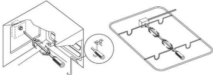
natural_image
Technical line drawing of a mechanical assembly with two views: one showing a bracket and tool, the other showing a grid-like component (no text or symbols)LIGHT
The light inside the oven can be switched on and off by the relative key, or by turning the oven knob.
CROSS FLOW COOLING FAN
The cross flow cooling allows the surface temperatures of the cooker to decrease thanks to the forced air recirculation between the oven door, the control panel and the oven cavity under the hob. The cross flow fan, located between the hob and the ceiling of the oven, automatically starts up a few minutes after the oven is switched on, and a device keeps it running even when the oven is switched off, until the outside of the oven cools down.
PRH FEATURE (if applicable)
This feature pre-heats the oven quickly, allowing you to reach the ideal temperature to start cooking. To enable it (in models without the digital timer/prog and mechanical cooking-end timer) turn the oven knob to the PRH feature to turn it on; the two Leds light uo (PRH-°C) and when the pre-heating cycle is finished they will go off. It is now possible to put the food in the oven and select the desired cooking feature.
BOTTOM COMPARTMENT (under the oven door)
Some models have a bottom compartment where the cooker's metal accessories can be stored when not in use.
Do not place flammable material, paper, rags etc. inside this compartment.
PROGRAMMERS AND MINUTE MINDERS
MINUTE MINDER
The minute minder is switched on by turning the knob clockwise to the end of its run, in order to load the mechanism, then counter-clockwise to set the required time. The time is expressed in minutes, a bell will let you know when the previously-set minutes are up.
COOKING-END MECHANICAL TIMER (only in models with an electric oven)
This mechanical timer, in addition to sounding the bell, also acts as a switch, by switching off the power. It is different from the minute minder because the ring nut around the knob (washer), in addition to indicating the minutes, also has the symbol of a hand. To set it, turn the knob to the end of its run, in order to load the mechanism, then turn it in the opposite direction to set the required time. If you wish to turn the oven on without setting any time, position the knob on the 'hand' symbol in the manual position.
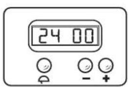
3 KEYS OF THE DIGITAL TIMER (fig. 3 - page 8)
- Set the time: press the timer on/off button (bell) immediately followed by the + or - key to adjust the time. Once it has been set, the time will automatically be set after 10 sec.
- Use the timer: to set the cooking time, press the + or - key until you reach the required amount of time (between 1 and 99 minutes). When the timer is on, it will appear on the screen. When the time is up, the timer will start ringing. To turn it off, press the timer on/off key (bell).
- set the timer at 1 minute and when you hear the bell, press the - key to change the volume.
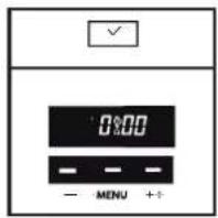
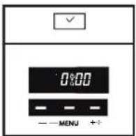
ELECTRONIC TIMER (fig. 4 - page 8)
- Set the clock: when the oven is first connected, or after a power failure, '0.00' will flash on the display. To set the clock, push the middle set button and the (+) or (-) buttons immediately to the disered time. The time of day will be saved after 10 seconds.
- Use the timer: It can be set for a maximum period of 99 minutes and minimum of 10 seconds. To set the timer just push the (+) or (-) button until you have set the required in minutes and seconds.
- When the timer is operating the timer on indicator will be lit. Once the pre-set time has elapsed, the timer will beep Push the SET button switch Off. The (-) button can also be uset to change the volume of the beep.
TOUCH PROGRAMMER (fig. 5 - page 8)
The touch programmer can work in 3 modes:
- MINUTE MINDER: once the time is set the timer will start counting down until it is up, and a bell will ring.
- AUTOMATIC END-COOKING: when the time is up, the oven will switch off and a bell will ring (only in models with electric ovens).
- DELAYED START: by setting the cooking time and the switch off time, the oven will start and stop automatically.
- Keyboard freeze: the programmer is equipped with automatic keyboard freeze after 7 seconds of inactivity. To unfreeze it, press any key for 2 seconds.
- Set the programmer time: hold the + and - keys down at the same time until the central cursor between the hour and minutes starts flashing. Then press + or - to set the time. Once you have reached the time you need to set, do not press any other key, and after a few seconds a beep will confirm the set time.
- Setting the count down (minute minder feature): the minute minder operates separately from the oven, and can be used for all cooking features. Hold the "Menu" key down until the screen changes. Release the key and adjust the time (minutes) by using the + and - keys. Once you reach the required time, release the key and wait for the confirmation beep. A bell icon will appear on the screen. At the end of the minutes, the bell will ring. Press any key to turn it off. To remove the bell icon from the screen, press the "Menu" key. To check the remaining amount of time (before it expires), hold the "Menu" key down. To delete the set amount of time, press the "Menu" key until the screen changes, and then press the + and - keys at the same time. The set amount of times will thus be deleted.
- Setting Auto Power Off (only for electric ovens): turn the oven on by adjusting features and temperatures. Hold the "Menu" key down until the screen changes, then press it again. The letters "DUR" (for 'duration') will appear on the screen. Press the + and - keys to adjust the cooking time. Wait for the confirmation beep without touching any keys. When the set amount of time is over, the oven will switch off and the beeping sound will be set off. Press any key to turn it off. To remove the bell icon from the screen, press the "Menu" key. To check the remaining amount of time (before it is over) hold the "Menu" key down. To delete the set amount of time, press the "Menu" key until the screen changes, and then press the + and - keys at the same time. Accordingly, the set amount of times will be deleted. At the end of cooking, remember to place the knob back to the "0" position.
- Setting delayed start (only for electric ovens): hold the "Menu" key down until the screen changes, then press it again. The letters "DUR" (for 'duration') will appear on the screen. Press the + and - keys to adjust the cooking time. Then press the "Menu" key once and the letters END will appear on the screen, indicating the menu to set the switch-off time. Press the + and - keys to adjust the switch-off time. Then select the cooking feature and required temperature. Obviously the oven will not start up immediately. Once the set amount of time has passed, the oven will switch off and the beep sound will start. Press any key to turn it off. To remove the bell icon from the screen, press the "Menu" key.
- Setting the volume: press + and - at the same time, followed by "Menu", to enter the tone setting mode and press the - key repeatedly to change the tone of the alarm. Once you have selected the tone, the timer will memorize your selection until you wish to change it again. Practical tips when using the programmer: please consider the amount of time for heating the oven when the cooking time is being set. Please switch the oven off at the end of the cooking cycles.
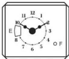
ANALOGUE CLOCK with hands (fig. 6)
- Setting the time: pull the rod (F) and turn clockwise until you have set the current time. When it is set, put the rod back in its initial position.
- Setting the cooking time: turn the rod (without pulling it) (F) clockwise and set the required minutes on the clock disk set at "9" (E). The maximum amount of time is 3 hours. When the time is over, a bell will ring. It will turn off automatically after three minutes. If you wish to turn it off manually, turn the rod clockwise until you see E, 0 or a crossed-out bell on the disk and in the E box.
- Setting the manual feature: Turn the rod clockwise to position I or ☐ exclude the minute minder.
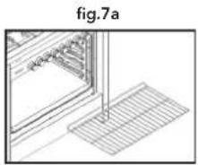
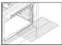
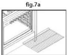
INSIDE RACKS (fig. 7-7a-7b)
The oven has 4 internal levels for the rack positioning (black rectangular baking rack or chrome-plated rack), where you can place the various dishes to be cooked. It is advisable to consult the cooking table in the following pages to use the best position and achieve the best cooking results.

Caution! The stop grid device requires the bracket to be inserted in the right position to work properly (fig. 7-7a-7b).
fig.3 fig.4 fig.5 fig.6 fig.7
text_image
24 00 - +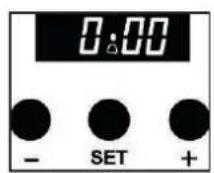
text_image
0:00 - MENU ++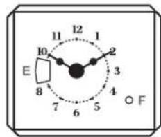
text_image
12 11 1 2 E 10 3 8 7 6 5 F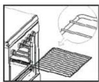
natural_image
Technical line drawing of a 3D object with grid overlay and label 'fig.7a' (no readable text or symbols)fig.7b
COOKING TIPS
COOKING FEATURES

OVEN LIGHT
It lights up the inside of the oven. It is useful to check the food cooking degree.

PIZZA
The pizza programme allows you to cook pizza as in a wood-burning oven.

TRADITIONAL COOKING
The heat is produced by the heating elements in the upper and lower parts of the oven. Excellent for pastries and traditional recipes.

UPPER ELEMENT
This feature allows direct cooking, excellent for lightly browning.

BOTTOM ELEMENT
The bottom heating element is on. Excellent for slow cooking, leavening and keeping food warm.

BOTTOM + FAN
The heat from the bottom heating element is ventilated (recommended to finish cooking and sterilizing).

FAN ASSISTED
The heat of the top and bottom heating elements, combined with that of the fan, allows excellent distribution of the heat, making it possible to cook several dishes.

CIRCULAR ELEMENT + FAN
The fan makes hot air circulate inside the oven, allowing even cooking on three levels, without transmitting odour.

PRE HEATING
This feature reduces the oven heating time, bringing the temperature to 200^ C in just a short time.

DEFROST
The fan operates without heating elements. This ensures optimal rapid defrost in just a few minutes.

GRILL
This is used to brown the food top. Excellent for cooking meat arranged in thin layers.

MAXI GRILL
The grill combined with the ceiling heating element makes it possible to grill larger surfaces.

GRILL + FAN
The grill combined with the fan spreads heat evenly. It is ideal for medium/thick meat, making it crisp on the outside and soft inside.

MAXI GRILL + FAN
Excellent to grill meat or fish.

GAS BURNER
Traditional gas cooking. Ideal for cooking that requires "humid" heat, such as meat and roasts.

TURNSPIT
Ideal for cooking game and roasts on a skewer It can be used with static or ventilated grill features.

GAS GRILL
Suitable for grilling meat and browning. Ideal in combination with the turnspit for cooking game.

GAS BURNER + FAN
The heat produced by the burner is ventilated, ensuring an even temperature and the possibility of cooking several dishes at the same time.
CLEANING
It is necessary to periodically clean the oven thoroughly to avoid the formation of grease, which over time can produce smoke, unpleasant odour and malfunctions. Below is a list of our tips concerning the various parts of your cooker.

WARNING
Do not use jets of steam to clean the appliance.
Steam could reach the electrical parts, damaging them and causing short circuits.
Do not use cleaning products that contain chlorine, ammonia or bleach on parts made of steel or superficially treated with metal finishes (for example anodizing, nickel-plating, chrome-plating).
USING THE HOB
It is advisable to clean the hob daily after every use, once it has cooled down, using specific products for steel, or a normal degreaser for coloured cookers. Be careful to remove all cooking residues. We strictly advise you against using abrasive or chlorine-based products.
CLEANING THE PAN SUPPORTS
The pan supports must be cleaned on a regular basis with warm water and non-abrasive detergent, being careful to remove all incrustations.
CLEANING THE BURNER BLACK CAPS AND FLAME SPREADERS
The burner caps and flame spreaders can be taken off to make it easier to clean the hob. Wash them with hot water and non-abrasive detergent, making sure they are thoroughly dry before being re-installed.
CLEANING THE SPARK PLUGS AND THERMOCOUPLES
To avoid malfunctions, check and keep the hob spark plugs and thermocouples clean. Remove any cooking residues by wiping them gently with a damp cloth.
CLEANING THE OVEN
For a good preservation of the oven it must be cleaned regularly after it has cooled down.
- Remove all removable parts.
- Clean the oven grids with hot water and non-abrasive detergents, rinse and dry.
• To make cleaning easier, it is possible to take the door and/or the glass off (refer to the maintenance paragraph). - At the end of these operations, to dry the damp parts thoroughly. It is advisable to turn the oven on for a maximum of 15/20 minutes after the use of specific cleaning products, in order to eliminate any residues from the inside of the oven.
- Do not use abrasive detergents or metal scrapers to clean the oven door glass as this may scratch the surface of the glass, causing its breakage.
MAINTENANCE

WARNING
Prior to every maintenance operation it is necessary to unplug the appliance from the power socket and wait for it to cool down completely.
CHANGING THE BULB INSIDE THE OVEN (fig. 8)
Unscrew the protective protruding cap inside the oven (A). Unscrew and change the bulb (B) with a new one with the same power and resistance to high temperatures (300°C). Put the cap back in place by screwing it in clockwise.
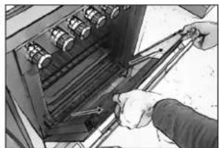
OVEN DOOR REMOVAL
DOOR WITH TRADITIONAL HINGE (fig. 9)
- Lift levers B and hold the door by its two sides with both hands, near hinges A.
- Lift the door upwards at an angle of approx. 45° and carefully pull it out. To re-assemble it, fit the hinges into the relative grooves, then let the door slide downwards, and release levers B.
DOOR WITH COMPACT HINGE (fig. 10)
- Lift levers "2" up to the ledge with hinges "1" and hold the door by its two sides with both hands, near the hinges.
- Lift the door upwards at an angle of approx. 45^ and carefully pull it out.
- To re-assemble it, fit hinge "2" into the relative grooves, then let the door slide downwards, making sure it stays blocked in the grooves "3", then release levers "1".
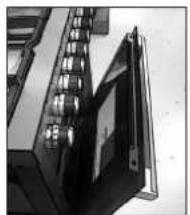
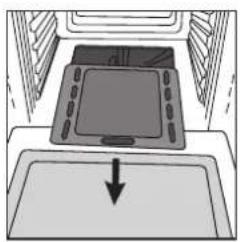
REMOVING THE GLASS FROM THE OVEN DOOR (only in applicable models)
This operation can only be carried out when the appliance is cold.
To take the glass out from the oven door, you must do the following:
- Open the door slightly.
- Press the black keys located on the side supports of the door at the same time, and slide them upwards.
- Remove the top profile of the door.
• Take the glass out by pulling it towards you.
To re-install the glass, follow these steps in reverse order being careful to align the glass with the side supports and making sure that the letters VIT are in the bottom right corner marked by the arrow. Lastly, put the top profile back in place on the door.
natural_image
Exterior view of a modern office building (no signage)
natural_image
Close-up of hands operating a mechanical device with rollers and a handle (no visible text or symbols)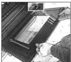
natural_image
Person using a printer to press or install a document (no visible text or symbols)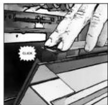
natural_image
Illustration of a hand pressing a small object on a mechanical component (no text or symbols visible)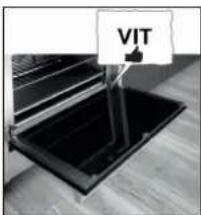
text_image
VIT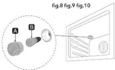
text_image
fig.8 fig.9 fig.10 A B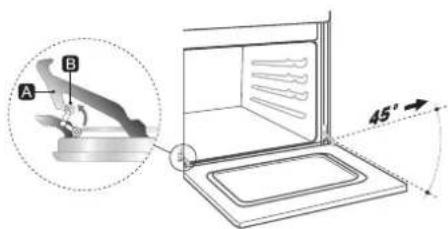
text_image
A B 45°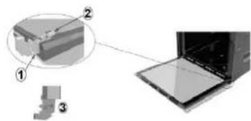
natural_image
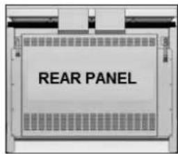
Diagram showing a device with three labeled components (①, ②, ③) and an open chamber, no text or symbols present.CHANGING THE POWER CABLE (this operation must be carried out exclusively by qualified personnel)
Disconnect the appliance from the power mains and take the rear panel off the cooker to have access to the terminal board (fig. 11). Loosen the clamping screws of the cable retainer and the screws on the terminal board that hold down the three cable conductors (fig. 12). The instructions listed below:
- Blue cable for Neutral on clamp N;
- Brown cable for Phase on clamp L;
- Yellow-Green cable for earth on clamp 12 .
Attach the cable to the corresponding cable clamp (brown terminal board) and re-assemble the rear panel of the cooker.
text_image
REAR PANEL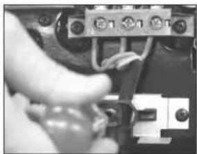
natural_image
Close-up of a hand holding a small electronic component with wires and connectors (no visible text or symbols)fig.11 fig.12
If the power cord is damaged, contact immediately the after sales service which will replace it.
INSTRUCTIONS FOR THE INSTALLER
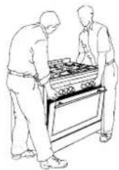
PRODUCT HANDLING
The product must be handled by two people.
Do not lift the cooker by the oven door handle, rather, open the door and hold the cooker by the top of the internal cavity. Do not drag or make the cooker slide.
INSTALLATION
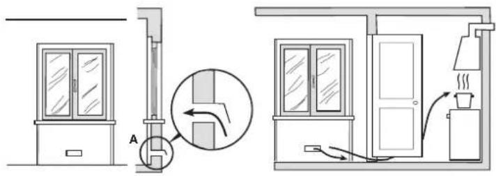
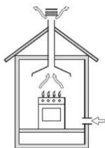
VENTILATION OF THE ROOMS (fig. 13)
This appliance can only be installed and made to operate in permanently ventilated rooms, in accordance with national legislation in force. It is essential that the amount of air required for gas combustion can flow through the room where the appliance is installed.
In particular, the air flow required for the correct combustion must not be lower than 2 m3/h for every kW of the appliance's rated power. (Refer to the technical data plate attached to the appliance, applied inside the door under the oven door or on the rear of the appliance).
The air must be drawn directly from the outside through permanent openings or ventilation ducts.
natural_image
Line drawing of two people inspecting a large outdoor stove (no text or symbols visible)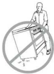
natural_image
Illustration of a person using a cart with a diagonal line and a 'no' symbol overlay (no text or symbols present)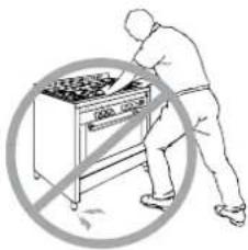
text_image
Safety warning symbol showing a person using a portable stove with a crossed-out circle indicating no protection.THE PRODUCT MUST BE INSTALLED WITH ITS LEGS.
text_image
Technical diagram illustrating installation or repair process with labeled components and instructions for confirmationCOMBUSTION GAS EXHAUST (fig. 14)

WARNING
It is essential that all operations relative to installation, regulation and technical maintenance are carried out exclusively by qualified personnel. The appliance must be installed in compliance with regulations in the country of use.
This appliance is not connected to an exhaust device for the combustion products. The appliance must convey the combustion products out into the atmosphere through a specific hood connected to a stack, flue or directly outdoors. Intense or prolonged use of the appliance may require supplementary ventilation, for example, the opening of a window, or more effective ventilation by increasing the level of mechanical ventilation, when applicable.
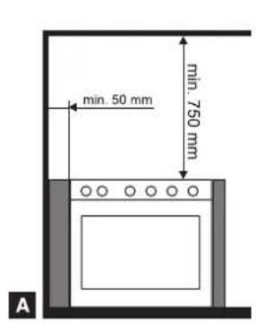
INSTALLATION (fig. 15 - page 12)
The appliance is class 1 and class 2.1 (see reference figure below). It can be free-standing or recessed (installed between other elements) in observance of the following minimum distances: 750 mm between the hob and any horizontal element above it (cabinets, for example); this space can be reduced to 650 mm if the above element is an extraction hood; 50 mm between the side of the appliance and elements that are taller than the appliance. It can be installed alongside walls that are higher then the work surface, at a minimum distance of 50 mm from the side of the appliance. If it is installed between elements, it is necessary that the walls of these elements be resistant to temperatures of up to 90 °C.
fig.13 fig.14
text_image
Diagram showing two room interior layouts with labeled components and airflow indicators, including a magnified inset of a door mechanism.ventilation opening for air flow required for correct combustion
enlarged hole to allow adequate air flow from the adjacent room
natural_image
Simple line drawing of a house interior with a stove, roof, and air duct (no text or symbols)direct exhaust out-take to the outdoors

natural_image
Simple line drawing of a house with steam rising from the chimney, showing airflow and ventilation (no text or symbols)exhaust out-take through the flue installed for the cooker only
text_image
min. 50 mm min. 750 mm A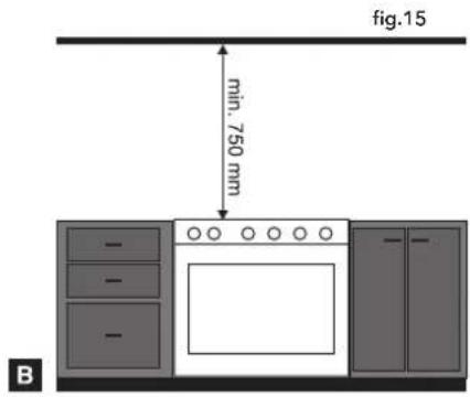
text_image
fig.15 min. 750 mm B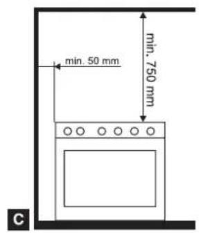
text_image
min. 50 mm min. 750 mm CA Recessed appliance (Class 2 sub-class 1)
B Recessed appliance (Class 2 sub-class 1)
C Free-standing appliance installation (Class 1)
natural_image
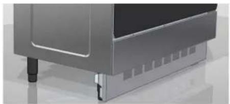
Close-up of a metallic electronic device with visible ports and mounting feet (no text or symbols)If a closing panel is applied on the feet of the kitchen, make sure that there is a grid with a passage section > 100 mm ^2 so as to guarantee proper ventilation of the gas burners inside the oven cavity.

WARNING
The cooker must be installed with its spacers provided inside the appliance. Please see photo below for the spacers installation:
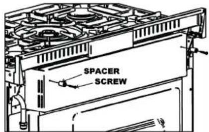
text_image
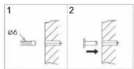
SPACER SCREWSTABILITY DEVICE (only if required by regulation in the country of use and provided as a kit together with the cooker)
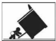

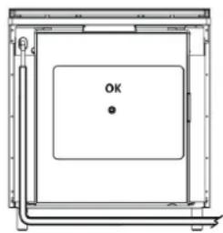
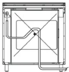
WARNING
To prevent accidental tipping of the appliance, it is necessary to install this stabilizing device as shown in the pictures below.
- Children should not play or sit, on the open oven door.
- Do not lean or sit, on the appliance's open door. The excessive load may compromise the stability.
- Do not place hot pans with sharp bottom, on the internal glass.
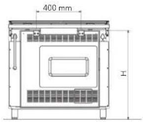
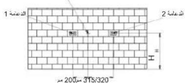
For model with a width of 50, 60, 70, 80, 90, 100 cm it is necessary to install rear safety devices, as an absolute guarantee against the appliance tipping forwards, even when bearing heavy loads on the open oven door.
- There is a rear cover panel installed on the rear of the cooker. Measure distance H from the highest point of the panel to the floor (A).
- Use the value of the H measurement to draw reference marks where the holes for the plugs will need to be drilled on the wall where the cooker will be installed (B).
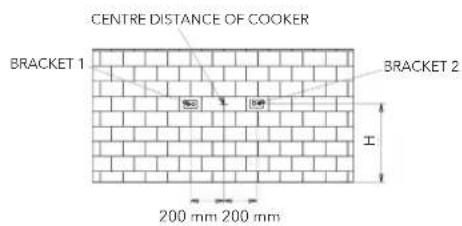
- Also mark the centre distance of the cooker on the wall at the same previously measured H height (C).
- It is now possible to install the two brackets at a distance of 400 mm from each other (200 mm from the centre distance) and position the cooker against the wall under the two brackets (D).
text_image
400 mm HABCD
text_image
CENTRE DISTANCE OF COOKER BRACKET 1 BRACKET 2 200 mm 200 mm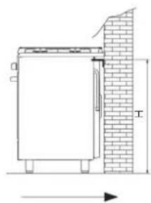
text_image
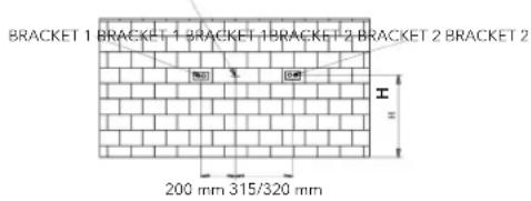
Technical diagram showing a cabinet with a brick wall and dimension line labeled '工' (work), indicating structural components.If your cooker has a 90x60, 80x50 cylinder cabinet, or 80x50 cabinet, it is necessary to assemble the brackets at the distance given in the pictures below:
CENTRE DISTANCE OF COOKER CENTRE DISTANCE OF COOKER CENTRE DISTANCE OF COOKER
text_image
BRACKET 1 BRACKET 1 BRACKET 1 BRACKET 2 BRACKET 2 BRACKET 2 H 200 mm 315/320 mm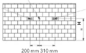
text_image
200 mm 310 mm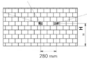
text_image
280 mm HCooker with 90 x 60 cylinder cabinet Cooker with 80 x 50 cylinder cabinet Cooker with 80 x 50 cabinet
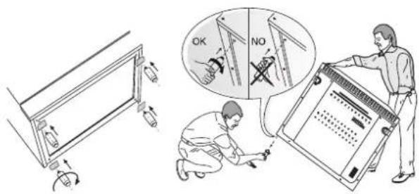
LEVELLING
Once the supplied feet are fitted and screwed in, if necessary, level the appliance by turning them. This will avoid any possible oscillation.
CONNECTION
GAS CONNECTION
While the connection to the gas mains or gas cylinder can be made with various types of tubes (flexible rubber or steel), it is nevertheless necessary to carry out this operation in accordance with regulations and amendments in force, once it has been ascertained that the appliance is properly adjusted to the type of gas it will be supplied with (see technical plate inside the bottom door or on the rear of the cooker).
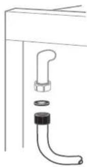
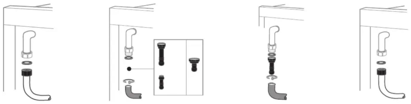
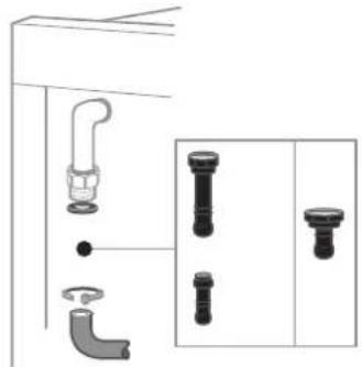
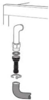
CONNECTION WITH FLEXIBLE METAL TUBE (fig. 16 - page 14)
The connection is made using a tube that is compliant with national regulation, connected to the appliance threaded fitting, through the use of a sealing joint (gasket). The maximum extension of the tube must not exceed 2 metres in length.
CONNECTION WITH FLEXIBLE RUBBER TUBE
This type of connection is not authorized when the appliance is recessed (class 2/1 appliance) and the tube can not be inspected for its entire length. Connect the tube connection to the threaded fitting through the use of a sealing joint (washer). Depending on the type of gas being used, the tubes will have different diameters:
• G30 (GPL) gas tube (fig. 17 - page 14) to be applied to tube connections with an 8 mm diameter;
• G20 (METHANE) gas tube (fig. 18 - page 14) to be applied to tube connections with a 12 mm diameter.
Fasten the two ends of the tube with the required tube clamps according to national regulations.
The tube must be replaced by the terms of the date printed on it and must not exceed the maximum length of 1.5 metres.
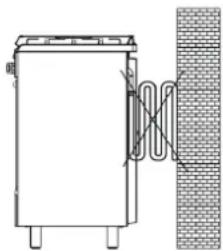
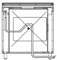
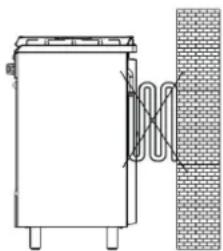
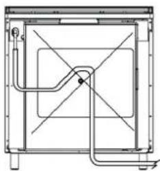
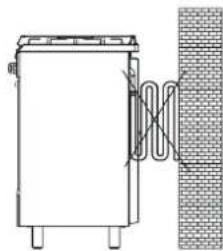
The tube must not come into contact with sharp objects, corners and with the cooker rear panel (see picture A); it must not be strained or twisted; no point of the tube must exceed a temperature of 50 °C .
fig. A
natural_image
Pure technical diagram of a rectangular enclosure with no text, numbers, or symbolsfig. b
natural_image
Pure technical line drawing of a mechanical or electrical component without any text, numbers, or symbolsfig. C
natural_image
Simple line drawing of a vertical container connected to a brick wall, with no text or symbols present.If the gas pipe is damaged, do not attempt to repair it by yourself but replace it with a new one before using the appliance.
GAS CONNECTION TO THE CYLINDER
With models with a cylinder cabinet it is possible to house cylinders with up to 15 kg of butane, that are compliant with national regulations. The cylinder must be equipped with a pressure reducer, compliant with national regulations.
The connection to the cylinder must be set up in compliance with installation standards pursuant to national regulations.
The flexible tube used for the connection must have an internal diameter of 8 mm, it must be compliant with standards and must be replaced before its expiration date. It must be fitted to the tube connection on the cooker and the pressure reducer using regulation tube clamps.
During the operations to connect the cylinder, it is necessary to follow the instructions below:
- the gas connecting tube must not exceed 1 meter in length;
- the pressure reducer fitting must face the door of the cylinder cabinet;
- the route of the flexible tube must not touch any hot surfaces of the cooker (the left inside wall of the cylinder cabinet, the rear of the cooker and cabinet ceiling) and IT MUST follow the route provided by the relative clamps;
- the cylinder must be set up so that it is not touching the wall adjacent to the oven.
Whenever you finish cooking, it is advisable to close the cylinder valve
CONNECTION WITH RIGID COPPER PIPE (fig. 19 - page 14)
Connect the rigid part to the threaded fitting located on the rear side of the appliance, through a regulation sealing joint.
SEAL CHECK
Following installation, make sure the fittings are firmly connected. Never use a flame to check the seal on the gas circuits, always use a soapy solution.
ELECTRICAL CONNECTION
Install a plug on the cable, suitable for the load stated on the specifications plate on the appliance (located inside the door under the over door, or on the rear of the cooker). The electrical connection must have an efficient earthing connection. The yellow-green conductor for the power cable must not have any switches set up along it. When there is a direct connection to the mains, it is necessary to set up a omnipolar switch between the appliance and the mains with a minimum opening between the contacts of 3 mm, sized for the load and compliant with national standards in force (the earth wire must not have any switches set up along it). The power cable must be positioned so that it does not exceed the ambient temperature by 50°C at any point. The manufacturing company will not be held liable in cases of failure to observe the electrical regulations in force, and if the connection has not been set up by qualified personnel.
fig.16 fig.17 fig.18 fig.19
ADAPTATION TO THE DIFFERENT TYPES OF GAS

WARNING
The appliance is designed to operate with different types of gas; each type of gas requires specific injectors and adjustments. To make any variations it is always necessary to cut the appliance off from the power mains and temporarily cut off the gas supply from the mains.
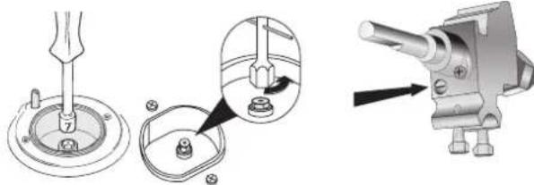
CHANGING HOB BURNER INJECTORS (fig. 20- page 15)
Manually remove the burners (no other disassembly operation is required) and using a suitable socket wrench, unscrew the injectors and replace them with the ones suitable for the type of gas, as listed in the technical data table and in the data plate on the cooker (see figure at the top of page 13).
REGULATING THE MINIMUM FLOW LEVEL OF GAS TO THE HOB BURNERS (fig. 21- page 15)
The regulation of the minimum flow rate of gas to the burners is carried out in factory. When an injector is changed to adapt it to the type of gas available, or following particular pressure conditions of the mains, it may be necessary to regulate the minimum again. Ignite the burner and let it operate on maximum capacity for approximately 10 minutes. Rotate the knob to the minimum position. Remove the knob by pulling it off the valve rod. With a small flat head screwdriver adjust the minimum by turning the by-pass screw clockwise to decrease the flame or counter-clockwise to increase the flame. When using valve cocks the adjustment screw (by-pass) is located on the body of the cock. When using valves other than valve cocks, the adjustment screw is situated inside the valve body. After any injectors replacement or adjustment operation always make sure that the flame is blue, steady and quiet and produces no detachment from the burner and will not cause backfire between the passage from maximum to minimum.
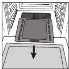
CHANGING BURNER INJECTORS INSIDE THE OVEN (fig. 22 - page 15)
Take the burners out by removing the clamping screws and using a suitable wrench to unscrew the injectors and replace them with the ones that are suitable for the type of gas, as listed in the technical data table.
REGULATING PRIMARY BURNER AIR INSIDE THE OVEN (only applicable to models with tube burners)
Loosen the corresponding screw by acting on the metal collar located on the end of the burner to adjust the air opening (by increasing or decreasing the amount of air) based on the result you wish to obtain. After any injector adjustment operation always make sure that the flame is blue, steady and quiet and produces no detachment from the back burner and will not cause backfire between the passage from maximum to minimum.
REGULATING THE MINIMUM FLOW RATE OF GAS TO THE OVEN AND GRILL BURNERS (fig. 23 - page 15)
Turn the burner on and position the knob on the maximum temperature. Let the oven heat up for at least 10 minutes. Rotate the knob to the minimum position. Pull the knob out of the thermostat rod and with a small flat head screwdriver adjust the minimum by turning the by-pass screw clockwise to decrease the flame or counter-clockwise to increase the flame. The flame should be short and steady; no air drafts or the closing of the door have to cause the extinguishing of the flame or its return. The adjusting screw (by-pass) is usually located on the body of the thermostat. When using valve cocks the adjustment screw (by-pass) is situated on the body of the cock (fig. 23 - page 15). When using valves other than valve cocks, the adjustment screw is situated inside the valve body.
After any action to change or adjust parts of the appliance, it is necessary to carefully re-assemble all affected parts to restore the original features. Any adaptations made for a different type of gas must be completed by changing the tube connection. In this case, also check the circuit seal with a soapy solution, and never with the use of a flame. Lastly, replace the old calibration label with a new one (included) for the new type of gas being used.
Your product is now correctly installed. Please remove all information labels and materials (located inside the oven) before turning it on.
fig.20 fig.21
natural_image
Technical illustration of a mechanical assembly with three stages: disassembly, mounting, and assembly (no text or symbols)fig.22 fig.23
natural_image
Diagram of a digital tablet device with an arrow pointing to it, placed on a screen (no text or symbols present)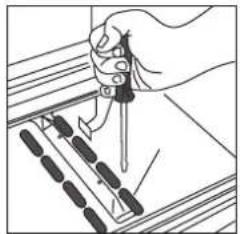
natural_image
Illustration of a hand using a pipette to measure a component on a tray (no text or symbols visible)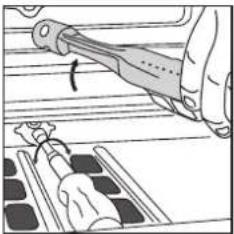
natural_image
Illustration of a hand using a tool to adjust or install a component, with no visible text or symbols.
natural_image
Diagram of a digital kitchen sink with a downward arrow indicating flow or direction (no text or symbols)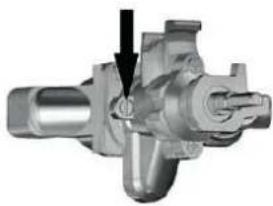
natural_image
Mechanical component diagram showing internal parts and a black arrow indicating direction (no text or symbols)TECHNICAL ASSISTANCE
To find an authorized service center near you, contact your dealer. We recommend having the information available on your technical data plate.
PRODUCT AND PACKAGING DISPOSAL
The packaging used on our products can be recycled, therefore we ask you not to dispose of the packaging or parts of it as household waste, and to dispose of it in the best way possible to reduce the effect on the environment. If you are purchasing our appliance to replace an old one, it is necessary to contact your locally authorized company for the collection of decommissioned appliances. This will allow the recyclable materials to be re-used and avoid polluting the environment.
The crossed-bin symbol cn the product indicates that Waste deriving from Electrical and Electronic Equipment (WEEE) must not be thrown away with genera waste(i.e. with the "mixed municipal waste"), but handled separately so as to be reused or be subjected to specific treatment remove and safely dispose of any substances that are harmful to the environment and extract the raw materials that can be recycled. In every member state of the European Union, WEEE should therefore be delivered to specialised Collection Centres in accordance with the provisions of the laws and regulations in force. The WEEE can also be handed over to the retailer when a new appliance is purchased, who is obliged to accept this free of charge ("one to ore" basis). The unlawful disposal of the product by the user will result in administrative sanctions.
CLEANING AND MAINTENANCE ADVICE FOR THE STAINLESS STEEL
Stainless steel can also be subject to considerable damage if not treated and if it is not constantly and carefully maintained.
Its resistance and duration are closely linked to its correct use, the optimal and constant maintenance and use of suitable cleaning products and materials certified to preserve its original characteristics.
The change in chemical-physical nature of the environment where it is located can quickly cause rather serious problems.
We can mention for example those environments with sea air and possible deposits of chlorides or sulphurous compounds in the air that can cause erosion.
MAIN CAUSES OF OXIDATION
- Ferrous residue left to settle on damp surfaces (not dry), with water in circulation, food or kitchen products used for cleaning the equipment (scrapers, steel wool, etc.)
- Ferrous residue in circulation from the extractor hood placed on the equipment (in the form of dust or micro-scales that deposit on the surfaces).
- Limescale, if not always removed, contributes to weakening (stress) the steel in the points or on the surfaces where it accumulates.
- Stainless steel, even if resistant to heat, can assume a bluish or brownish colour under the action of an anomalous flame that manifests if saucepans are used with an unsuitable diameter.
- Detergents with a chlorine or ammonia base.
- Scale or food residue left for long periods of time.
- Start-up and use of the equipment with dry containers (without the minimum quantity of content inside e.g. a typical situation is the preparation of sauté), resulting in stressing the metal due to overheating.
- Chlorine-based cleaning products, for example bleach or similar products regularly found on the market, since they can produce serious corrosive effects.
- The direct contact or only the vapours released from acidic products (muriatic acid, hydrochloric acid), alkaline products (sodium hypochlorite/bleach) or ammonia, used directly or contained in common detergents, to clean and sanitise flooring, tiles and washable surfaces.
- Placing or using cloths, sponges or other items used for cleaning other products or other materials on it. It is equally important to know that using steel wool or other similar items to remove solid or stubborn food residue can leave microscopic particles, which detaching from those objects, deposit on the surface of the equipment and through contact trigger a rapid and irreversible or difficult to clear corrosion process if not quickly worked on (a ferrous particle left in a damp environment takes just a few hours to trigger serious corrosion).
RECOMMENDATIONS
- Avoid salty solutions drying or remaining on the surface, because they can cause corrosion phenomena.
- Avoid prolonged contact with ferrous material (steel wool, carving forks, ladles, scrapers, etc.) to avoid triggering corrosion, from contamination of the ferrous particles in circulation.
- Carefully clean the stainless steel surfaces using a damp cloth (e.g. microfibre), water and soap and common, non-abrasive and chlorine-free detergents.
- Wipe in the satin direction, if satin-finished.
- Rinse well and dry carefully.
- Only use specific products for stainless steel cleaning. You are advised to use commercial emulsion products.
HOW TO CLEAN...
Limescale
Use a multi-purpose detergent cream with a damp cloth (e.g. microfibre). You can also use white vinegar, possibly hot, rubbing with a soft cloth (e.g. microfibre) and then rinsing well and drying.
Oil and grease stains
Use mild washing-up liquid or a mild detergent in very hot water. Rinse with plenty of clean water and dry with a soft cloth (e.g. microfibre). For more stubborn stains use ethyl alcohol or white vinegar.
Fingerprints
Use a mild detergent or washing-up liquid in water or, alternatively, delicately wipe with a soft cloth (e.g. microfibre) and window cleaner.
Flame streaks
Use a soft cloth (e.g. microfibre) with a multi-purpose, cream detergent for household cleaning. Rinse under running water and dry with a soft cloth (e.g. microfibre).
Coffee or tea stains, stubborn dirt, burnt-on grease
Use a soft cloth (e.g. microfibre) with a specific emulsion detergent to clean stainless steel. Remember that food and liquids must be immediately removed from stainless steel surfaces.
Glue left by adhesives, glue streaks
According to the adhesive substance, the residue can be eliminated with water, alcohol or acetone based solvents which, as known, do not affect stainless steel.
Rust stains (contamination)
Rust stains may not be caused by corrosion of stainless steel, but instead:
- Objects (jars, utensils used daily, etc.) in common steel left for prolonged periods on stainless steel surfaces or which can transfer ferrous particles.
- Use of aggressive products to clean stainless steel.
• Ferrous residue in circulation from extractor hoods placed over the equipment. - Direct contact with or only the vapour from acidic, alkaline or ammonia based products.
- Contact with rags, sponges or other similar objects, used to clean other objects or other materials.
To remove these stains, apply a cream detergent using a soft, damp cloth (e.g. microfibre) and wipe delicately.
Instead, if rust is already present, you need to cover the relevant part again with a lemon and salt mix and leave to act for a few minutes. The rust will quickly detach thanks to the action of the lemon and you can remove it with a soft sponge.
The rust that will detach will most likely weaken the metal where slight cavities may have formed.
REMEMBER: it is good practice to test any new products for stainless steel cleaning on out of sight parts and wait a few hours to assess the effect.
ATTENTION
NEVER USE steel wool, brushes, abrasive discs, or metal utensils for cleaning.
In fact, if these objects were used previously to clean other metals, not only would they scratch the surface but they would also cause contamination, resulting in unsightly stains or even the appearance of rust.
NEVER USE hydrochloric acid (commercial muriatic acid). You should also avoid contact with hydrochloric acid vapours, for example coming from washing floors. In general, you should avoid direct use of chlorine-based products on stainless steel.
NEVER USE abrasive powder detergents that could damage the aesthetic appearance of the surface finish.
NEVER USE substances for silver cleaning.
REMEMBER
•HYDROCHLORICACID
- BLEACH with a hypochlorous acid base
- CHLORIDES in general
Stainless steel in contact with these substances can create surface stains that are difficult to eliminate or even traces of rust.
Exclusion of liability: the information contained in this document should only be considered as useful advice for the maintenance of stainless steel surfaces. Glem Gas S.p.A. cannot be held in any way liable for costs or damage resulting from the use of information contained in this document.
TECHNICAL DATA
| BURNER TYPE(sizes mm) | GAS TYPE | PRESSURE(mbar) | INJECTORMARKING(1/100 mm) | POWER (kW) | RECOMMENDED POT DIAMETER**(cm) | |
| MAX. MIN. | ||||||
| AUXILIARY∅ 39 | LPG 30 | 46 | 0,800 0,300 | 12÷146 with reduction grill | ||
| natural gas 20 | 68 | |||||
| AUXILIARY∅ 55 | LPG 30 | 52 | 1,000 0,300 | 12÷146 with reduction grill | ||
| natural gas 20 | 72 | |||||
| SEMIRAPID∅ 75 | LPG 30 | 68 | 1,750 0,440 | 16÷20 | ||
| natural gas 20 | 98 | |||||
| RAPID∅ 100 | LPG 30 | 88 | 3,000 0,750 | 20÷24 | ||
| natural gas 20 | 116 | |||||
| FISH BURNER60x235 | LPG 30 | 88 | 2,900 1,500 | Max14÷35 | ||
| natural gas 20 | 120 | |||||
| TRIPLE∅ 130 | LPG 30 | 96 | 3,600 1,800 | 24÷28 | ||
| natural gas 20 | 135 | |||||
| TRIPLE∅ 130 | LPG 30 | 98 | 3,800 1,800 | 24÷28 | ||
| natural gas 20 | 137 | |||||
| DCC | LPG 30 | 91 | 3,800 1,800 | 24÷28 | ||
| natural gas 20 | 135 | |||||
* In reference conditions, gas temperature 15°C, atmospheric pressure 1013.25 mbar.
** In compliance with burners and pots specifications.
POWER OF HEATING ELEMENTS
| COOK-TOP | |||||
| Diameter (mm) | Power (Watts) | Diameter (mm) | Power (Watts) | ||
| Electric plate Normal 1 | 45 1000 Circular High-Light | 145 | 1200 | ||
| Electric plate Normal 1 | 45 1500 Circular High-Light | 180 | 1800 | ||
| Electric plate Rapid | 180 | 2000 | Circular High-Light | 210 | 2200 |
| Extensible High-Light 1 | 20/210 700/2100 | ||||
| Extensible High-Light 1 | 70/265 1400/2200 | ||||
| OVEN | Storage Compartment Element (Watts) | |||||
| OVEN CAPACITY (Liters) | Bottom Element (Watts) | Top Element (Watts) | Grill Element (Watts) | Double-Grill Element (Watts) | Circular Element (Watts) | |
| 123 | 1500 | 950 | 2000 | 2950 | / | / |
| 111 1500 950 1500 2450 2400 / | ||||||
| 105 1500 950 2000 2950 / | / | |||||
| 95 | 1500 950 1500 2450 2400 / | |||||
| 90 | 1500 | 950 | 2000 | 2950 | / | / |
| 80 | 1500 950 1500 2450 2400 / | |||||
| 67 | 1400 | 850 | 1400 | 2250 | / | / |
| 61 | 1400 850 1400 2250 2200 / | |||||
| 61 Double Oven | 1100 700 1400 2100 2200 500 | |||||
| 58 | 1100 | 650 | 1350 | 2000 | / | / |
| 51 | 1100 650 1350 2000 2200 / | |||||
| 47 | 900 | 600 | 1350 | 1950 | / | / |
| 37 Double Oven | 800 | 500 | 1200 | 1700 | / | 500 |
TECHNICAL DATA
| VOLUME OVEN / BURNER GAS TYPE | PRESSURE (mbar) | INJECTOR MARKING (1/100 mm) | GAS CONSUMPTION* | POWER (kW) | ||
| MAX. MIN. | ||||||
| Oven burnerVolume cavity: 37 - 41 l (dm3)Small oven/double oven cookerCooker dimensions (WxD): 90x60 or 100x60 | LPG 50 58 | 145 g/h | 2,000 0,700 | |||
| natural gas 20 | 108 190 dm | ^3/h | ||||
| Oven burnerVolume cavity: 45 - 70 l (dm3)Single oven cookerCooker dimensions (WxD): 50x50, 60x50, 70x50, 60x60,Bottle compartment 80x50, Bottle compartment 90x60Big oven/double oven cookerCooker dimensions (WxD): 90x60 or 100x60 | LPG 50 62 | 193 g/h | 2,650 1,000 | |||
| natural gas 20 | 122 252 dm | ^3/h | ||||
| Oven burnerVolume cavity: 74 - 109 l (dm3)Single oven cookerCooker dimensions (WxD): 80x50 or 80x60 | LPG 50 80 | 276 g/h | 3,800 1,000 | |||
| natural gas 20 | 145 362 dm | ^3/h | ||||
| Oven burnerVolume cavity: 102 - 126 l (dm3)Single oven cookerCooker dimensions (WxD): 90x60 or 100x60 | LPG 50 88 | 305 g/h | 4,200 1,000 | |||
| natural gas 20 | 150 400 dm | ^3/h | ||||
| Grill burnerVolume cavity: 37 - 41 l (dm3)Small oven/double oven cookerCooker dimensions (WxD): 90x60 o 100x60 | LPG 50 56 | 116 g/h | 1,600 | |||
| natural gas 20 | 101 152 dm | ^3/h | ||||
| Grill burnerVolume cavity: 45 - 70 l (dm3)Single oven cookerCooker dimensions (WxD): 50x50, 60x50, 70x50, 60x60,Bottle compartment 80x50, Bottle compartment 90x60Big oven/double oven cookerCooker dimensions (WxD): 90x60 o 100x60 | LPG 50 60 | 145 g/h | 2,000 | |||
| natural gas 20 | 108 190 dm | ^3/h | ||||
| GRILL (dm3 80/123)85-86/96-16 (large oven and giant oven) | LPG 50 68 | 192 g/h | 2,600 | |||
| natural gas 20 | 120 252 dm | ^3/h | ||||
* In reference conditions, gas temperature 15°C, atmospheric pressure 1013.25 mbar.
** In compliance with burners and pots specifications.
COOKING TABLE
| PIATTO | STATIC OVEN (no fan) ELECTRIC OR GAS | VENTILATED OVEN (multi level cooking) | COOKING TIME | ||
| cooking level inside rack | temperature °C | cooking level inside rack | temperature °C | minutes | |
| Desserts | |||||
| Shortcrust pastry 3 190-200 2 (1-3) 180-190 30-35 | |||||
| Mixed-dough cake 2 200-210 2 (1-3) 190-200 30-35 | |||||
| Pie 2 190-200 2 (1-3) 180-190 30-35 | |||||
| Plum cake 3 190-200 2 (1-3) 180-190 30-35 | |||||
| Fruit cake 3 175-190 2 (1-3) 165-180 35-45 | |||||
| Nut cake 3 190-200 2 (1-3) 180 190 40-45 | |||||
| Strudel 2 195-200 2 (1-3) 185-195 35-45 | |||||
| Sponge cake 2 195-210 2 (1-3) 185 | 35-45 | ||||
| Cream Caramel | 3 130-150 | 2 (1-3) 130 | 30-35 | ||
| Chocolate cake | 2 | 180-190 | 2 (1-3) | 180 | 35-40 |
| Croissants | 2 190-200 | 2 (1-3) 180-190 | 25-30 | ||
| Cookies | 2 | 180 | 2 (1-3) | 165 | 20 |
| Pastries | 3 230-250 | 2 (1-3) 200-230 | 10-15 | ||
| Scones | 1 | 190-210 | 1 (1-2) | 180-190 | 20 |
| Muffins | 3 205-220 | 2 (1-3) 185-200 | 25-35 | ||
| Bread and pizza | |||||
| Pizza | 2 215-230 | 2 (1-3) 195-210 | 20-30 | ||
| Focaccia | 2 | 220 2 (1-3) | 190-210 20-30 | ||
| Bread | 3 235-250 | 3 (2-3) 215-230 | 40-50 | ||
| Bread | |||||
| Lasagne | 3 185-200 | 2 (2-4) 165-180 | 30-40 | ||
| Baked pasta | 3 190-200 | 2 (2-4) 180-190 35-45 | |||
| Vegetable flans | 2 180-190 | 2 (1-3) 170-180 | 30-40 | ||
| Roasted meat | |||||
| 1 Kg beef 2 220-225 2 (1-3) 200-220 50-60 | |||||
| 1 Kg lamb 2 190-220 2 (1-3) 180-200 50-60 | |||||
| 1 Kg veal | 2 190-220 | 2 (1-3) 180-200 | 60-70 | ||
| Chicken | 2 205-215 | 2 (1-3) 195-210 | 40 | ||
| Duck | 2 210-220 | 2 (1-3) 195-210 | 120-180 | ||
| Goose | 2 210-220 | 2 (1-3) 195-210 | 120 | ||
| Turkey | 2 215-230 | 2 (1-3) 195-210 | 120 | ||
| Rabbit meat | 2 215-235 | 2 (1-3) 200-200 | 40 | ||
| Pheasant | 2 205-215 | 2 (1-3) 195-210 | 40-50 | ||
| Fish | |||||
| Fillets and slices | 2 170-180 | 2 (1-3) 160-170 | 20-30 | ||
| Roasted meat | 2 190-200 | 2 (1-3) 180-190 | 25-35 | ||
| Baked in tin foil | 2 200-210 | 2 (1-3) 190-200 | 25-35 | ||
Cooking notes
The data provided here must be considered a guideline. Therefore, it can and must be changed based on your own tastes and habits.
The time reported in the table does not include the pre-heating function, which is always recommended.
The time and temperature provided refer to an average amount of food: 1/1.5 kg for meat, pastry/pizza/bread dough 0.5/0.8 Kg.
Multiple cooking on several levels must be carried out by putting the containers in the centre of each rack.
GRILLING TABLE
| DISH | cooking level inside rack | temperature °C | cooking time minutes |
| Toast | 3-4 | 200 | 3-4 |
| Hamburgers | 3-4 | 200 | 5-7 |
| Fish skewers | 3-4 | 200 | 6-8 |
| Shellfish | 3-4 | 200 | 6-8 |
| Sausages | 3-4 | 200 | 7-10 |
| Ribs | 3-4 | 200 | 7-10 |
| Meat skewers | 3-4 | 200 | 8-10 |
| Steaks | 3-4 | 200 | 8-12 |
| Chicken | 3-4 | 200 | 30-35 |
Grilling notes:
- 5-10 minutes pre-heating is enough for recipes that require it.
• The stated amount of time refers to only one side of the dish, it is therefore necessary to turn it.
- Grilling with a closed door is only possible with ventilated cookers. Other models use the specific heat insulating device to grill with the door partially open.
- Put a baking tray on the rack below with a cup of water in it (0.2 l) to limit grease drops and excessive smoke during cooking.
36 Assistance technique
** The reduction grill, FOR models that include it, must only be used for the auxiliary burner when cooking with pots with a diameter less than 12 cm.
natural_image
Close-up of a rotary press mechanism with curved arrows indicating rotation (no text or symbols visible)Picture A
natural_image
Close-up of a dual rotary switch mechanism with no visible text or symbolsPicture B
CUISINIÈRE AVEC FOUR ÉLECTRIQUE
natural_image
Technical line drawing showing mechanical assembly with a magnified inset (no text or symbols)ÉCLAIRAGE
text_image
24 00 - +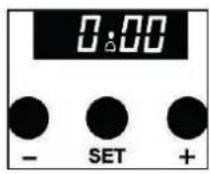
text_image
12 11 1 10 E 8 7 6 5 4 3 2 O F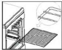
natural_image
Technical line drawing of a window with a grid base and a vertical rod, labeled 'fig.7a' (no text or symbols on the diagram itself)fig.7b
CONSEILS DE CUISSON
FONCTIONS CUISSON

LAMPE DU FOUR
natural_image
Close-up of a hand holding a small electronic component with wires and connectors (no visible text or symbols)fig.11 fig.12
MANUTENTION DU PRODUIT
natural_image
Line drawing of two people inspecting a large oven (no text or symbols)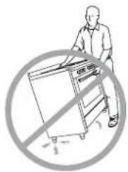
natural_image
Illustration of a person using a device to stop a window, with no text or symbols present.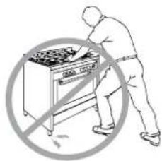
natural_image
Illustration of a person using a portable stove with a no-smoking symbol (no text or labels)INSTALLATION
VENTILATION DE LA PIÈCE (fig. 13)
text_image
Diagram illustrating electrical switch installation and maintenance, showing device states and fault indicators (OK/NO)ÉCHAPPEMENT DES GAZ DE COMBUSTION (fig. 14)

MISE EN GARDE
natural_image
Technical diagram showing a door frame and a vertical structural component with an arrow indicating rotation (no text or symbols present)natural_image
Simple line drawing of a room with a door, chimney, and steam rising (no text or symbols)natural_image
Simple line drawing of a house interior with a stove, roof, and airflow indicators (no text or symbols)natural_image
Simple line drawing of a house with steam rising from the chimney, showing airflow and ventilation (no text or symbols)natural_image
Close-up of a metallic kitchen appliance with visible door, legs, and ventilation slots (no text or symbols)natural_image
Technical line drawing of a cabinet with a brick wall and height dimension H, showing structural details (no text or symbols)natural_image
Pure technical diagram of a rectangular enclosure with no text, numbers, or symbolsfig.b
natural_image
Technical line drawing of a mechanical enclosure or enclosure with internal components and no visible text or symbolsfig. C
natural_image
Technical line drawing of a mechanical device with a brick wall and coiled spring (no text or symbols)text_image
fig.20 fig.21fig.22 fig.23
natural_image
Simple line drawing of a device with a downward arrow pointing to its surface (no text or symbols)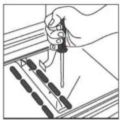
natural_image
Illustration of a hand using a tool to adjust or install a component, with no visible text or symbols.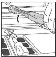
natural_image
Illustration of a hand using a tool to adjust or install a component, with no visible text or symbols.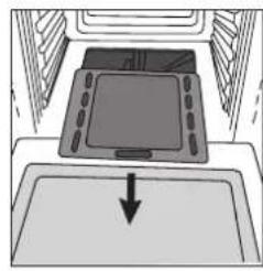
natural_image
Diagram of a kitchen sink with a monitor and arrow indicating direction (no text or symbols)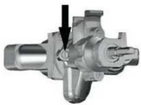
natural_image
Mechanical component diagram showing a valve assembly with a black arrow indicating direction (no text or symbols present)ASSISTANCE TECHNIQUE
PRINCIPALES CAUSES D'OXYDATION
natural_image
Line drawing of a simple kitchen oven with five windows (no text or symbols)مو اقد
natural_image
Close-up of a mechanical device with two circular components and directional arrows indicating motion (no visible text or symbols)A الصورة
natural_image
Close-up of two circular industrial gauges with rotating blades, no visible text or symbolsB الصورة
natural_image
Technical line drawing of a mechanical assembly with two views: one showing a tool inserted into a housing, the other showing a bracket with pins and a wire (no text or symbols present)سيخ الشواء
natural_image
Close-up of a hand holding a small electronic component with wires and connectors (no visible text or symbols)natural_image
Line drawing of two people handling a large appliance or stove (no text or symbols visible)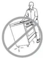
natural_image
Illustration of a person using a laptop with a prohibition symbol (no text or symbols present)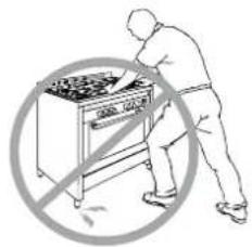
text_image
Safety warning symbol showing a person using a portable stove with crossed-out hand gesturenatural_image
Technical line drawing of a rectangular frame with directional arrows indicating rotation (no text or symbols)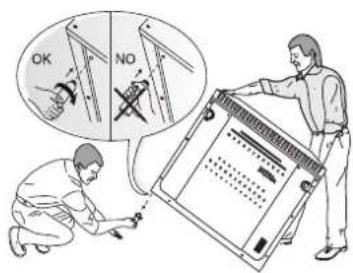
text_image
OK NOنقل المنتج
text_image
Diagram illustrating a door heating system with labeled components and airflow directionnatural_image
Two schematic diagrams of a greenhouse with steam rising from the roof, showing internal heating and ventilation systems (no text or labels)natural_image
Exterior view of a modern office building (no signage)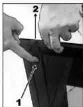

natural_image
Close-up of hands operating a mechanical device with multiple cylindrical components (no visible text or symbols)
natural_image
Close-up of hands operating a printer with a magnified inset showing a small object (no visible text or symbols)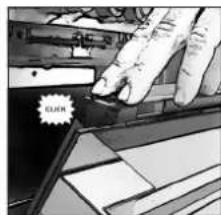
text_image
RICH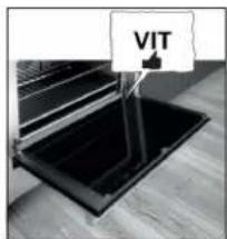
text_image
VIT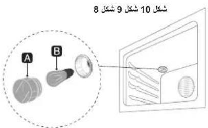
text_image
A B 8 10 9 shckl 8
text_image
A B A 45°→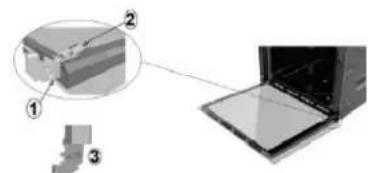
natural_image
Diagram showing a 3D object with labeled parts and an open oven (no text or symbols present)مُتَصْفِ الْمُسَّالَةِ الْخَاسَةِ بِلَّمُرِكِ مَتَصْفِ الْمُسَّالَةِ الْخَاسَةِ بِلَّمُرِكِ مَتَصْفِ الْمُسَّالَةِ الْخَاسَةِ بِلَّمُرِكِ
text_image
1 العربية 2 العربية H 200m 375/320-natural_image
Pure technical diagram of a rectangular enclosure with no text, numbers, or symbolsfig.b
natural_image
Pure technical line drawing of a mechanical or electrical component without any text, numbers, or symbolsfig. C
natural_image
Simple line drawing of a portable air conditioner unit connected to a brick wall (no text or symbols)natural_image
Close-up of a metallic electronic device with visible ports and mounting feet (no text or symbols)natural_image
Technical line drawing of a door frame with a brick wall and directional arrow (no text or symbols)natural_image
Simple line drawing of a monitor with an arrow pointing to it, above a rectangular panel (no text or symbols)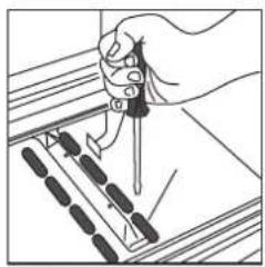
natural_image
Illustration of a hand using a tool to adjust or install a component, with no visible text or symbols.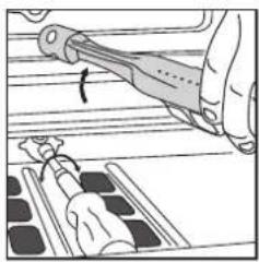
natural_image
Illustration of a hand using a tool to adjust or install a component, with no visible text or symbols.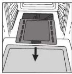
natural_image
Simple line drawing of a device with a downward arrow pointing to it, no text or symbols present.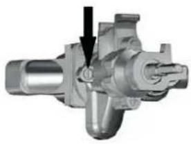
natural_image
Mechanical component diagram showing a valve assembly with a black arrow indicating direction (no text or symbols present)الدعم الفني
natural_image
Diagram of a kitchen sink with pipe and tubing components (no text or labels)17 شكل
natural_image
Diagram of a bathroom sink with pipe fittings and a close-up view of a double-bore toilet (no text or labels)18 شكل
natural_image
Diagram of a kitchen sink assembly showing pipe, valve, and PVC pipe (no text or labels)19 شكل