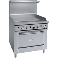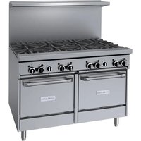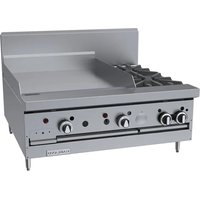
GF36-2G24T - Cooker GARLAND - Free user manual and instructions
Find the device manual for free GF36-2G24T GARLAND in PDF.


User questions about GF36-2G24T GARLAND
0 question about this device. Answer the ones you know or ask your own.
Ask a new question about this device
Download the instructions for your Cooker in PDF format for free! Find your manual GF36-2G24T - GARLAND and take your electronic device back in hand. On this page are published all the documents necessary for the use of your device. GF36-2G24T by GARLAND.
USER MANUAL GF36-2G24T GARLAND
natural_image
Exterior view of a two-wheeled kitchen stove with dual doors (no visible text or symbols)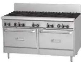
natural_image
Exterior view of a stainless steel commercial kitchen with two large cabinets and top grating (no visible text or symbols)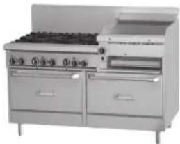
natural_image
Exterior view of a modern stainless steel cooktop appliance with two doors and a front-mounted stove (no visible text or symbols)




All 24, 36, 48, & 60-inch wide models.
Français Page 21
DO NOT STORE OR USE GASOLINE OR OTHER FLAMMABLE VAPORS OR LIQUIDS IN THE VICINITY OF THIS OR ANY OTHER APPLIANCE
WARNING:
IMPROPER INSTALLATION, ADJUSTMENT, ALTERATION, SERVICE OR MAINTENANCE CAN CAUSE PROPERTY DAMAGE, INJURY, OR DEATH. READ THE INSTALLATION, OPERATING AND MAINTENANCE INSTRUCTIONS THOROUGHLY BEFORE INSTALLING OR SERVICING THIS EQUIPMENT
PLEASE READ ALL SECTIONS OF THIS MANUAL AND RETAIN FOR FUTURE REFERENCE.
THIS PRODUCT HAS BEEN CERTIFIED AS COMMERCIAL COOKING EQUIPMENT AND MUST BE INSTALLED BY PROFESSIONAL PERSONNEL AS SPECIFIED.
IN THE COMMONWEALTH OF MASSACHUSETTS THIS PRODUCT MUST BE INSTALLED BY A LICENSED PLUMBER OR GAS FITTER.
For Your Safety:
Post in a prominent location, instructions to be followed in the event the user smells gas. This information shall be obtained by consulting your local gas supplier.
Users are cautioned that maintenance and repairs must be performed by a Garland authorized service agent using genuine Garland replacement parts. Garland will have no obligation with respect to any product that has been improperly installed, adjusted, operated or not maintained in accordance with national and local codes or installation instructions provided with the product, or any product that has its serial number defaced, obliterated or removed, or which has been modified or repaired using unauthorized parts or by unauthorized service agents. For a list of authorized service agents, please refer to the Garland web site at http://www.garland-group.com. The information contained herein, (including design and parts specifications), may be superseded and is subject to change without notice.
GARLAND COMMERCIAL RANGES, LTD.
1177 Kamato Road, Mississauga, Ontario L4W 1X4
CANADA
Phone: 905-624-0260
Fax: 905-624-5669
WARNING:
This product contains chemicals known to the State of California to cause cancer and/or birth defects or other reproductive harm. Installation and servicing of this product could expose you to airborne particles of glass wool/ceramic fibers. Inhalation of airborne particles of glass wool/ceramic fibers is known to the State of California to cause cancer. Operation of this product could expose you to carbon monoxide if not adjusted properly. Inhalation of carbon monoxide is known to the State of California to cause birth defects or other reproductive harm.
Keep appliance area free and clear of combustibles.
TABLE OF CONTENTS
IMPORTANT INFORMATION......2
DIMENSIONS AND SPECIFICATIONS ..... 4
Base Model Designations & Total Input Rates .. 5
Clearances....5
Gas Pressure & Individual Burner Input Rates .. 6
North America 6
CE & General Export 6
Reduced Input Rates 6
Australia 7
Gas Inlet Size 7
CE Approved Gas Categories .....7
INTRODUCTION....8
Rating Plate....8
Safety Information 8
INSTALLATION....9
Siting....9
Appliances Equipped With Casters....9
Appliances Equipped With Legs 9
Installing Shelf To Backguard 9
Backguard With High Shelf Or Salamander
Mounting Instructions 9
Ventilation Air 10
Statutory Regulations....11
Australia Specific Clause.... 11
Electrical Connection Settings (Where
Applicable)....11
Gas Connection....11
Final Preparation....12
Optional Interconnect Gas Kit # 4523975 ..... 12
TESTING AND ADJUSTMENT ..... 13
Testing....13
OPERATION....13
Flame Failure Technology ....13
How Flame Failure Technology Works.....13
Burner Operation ....14
Open Top burners ....14
Hot Tops....14
Ovens (Standard) 15
Convection Ovens ....15
Thermostat Controlled Griddles .....16
Griddle/Broiler....17
Range Shut down....17
PRODUCT APPLICATION INFORMATION 18
General....18
Open Burners....18
Hot Tops....18
MAINTENANCE AND CLEANING.....19
Seasoning....19
Griddle 19
Cast Iron top Grates 19
Stainless Steel 19
Oven Interior (Porcelain Enamel)....19
Open Top Burners 19
Cast Iron Top & Grates....20
Hot Tops....20
Griddle....20
WIRING DIAGRAMS ....65
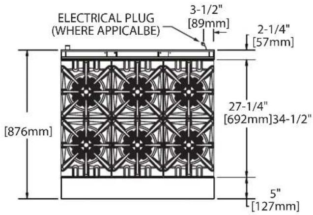
DIMENSIONS AND SPECIFICATIONS
Top View
Model widths vary depending on model series.
(See Chart on left)
text_image
ELECTRICAL PLUG (WHERE APPICALBE) 3-1/2" [89mm] 2-1/4" [57mm] 27-1/4" [692mm]34-1/2" [876mm] 5" [127mm]| SeriesWidth |
| GF24 600mm (23-5/8")* |
| GF36 900mm (35-2/2")* Shown |
| GF48 1200mm (47-1/4") |
| GF60 1500mm (59-1/2") |
| *Range base or modular top |
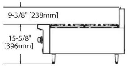
Modular Top Models GF24-_T or GF36-_T Side View
text_image
9-3/8" [238mm] 15-5/8" [396mm]GF Series Side View
(Showing convection base where applicable).
text_image
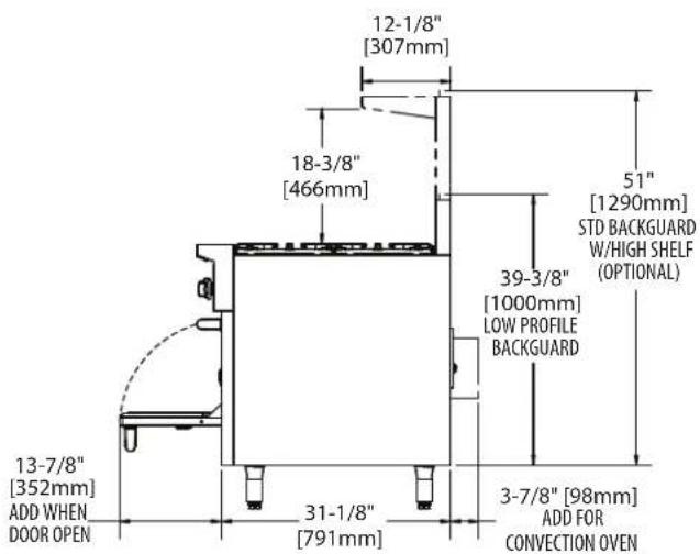
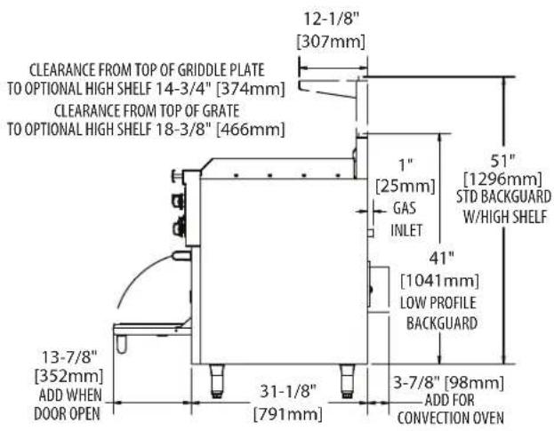
12-1/8" [307mm] 18-3/8" [466mm] 51" [1290mm] STD BACKGUARD W/HIGH SHELF (OPTIONAL) 39-3/8" [1000mm] LOW PROFILE BACKGUARD 13-7/8" [352mm] ADD WHEN DOOR OPEN 31-1/8" [791mm] 3-7/8" [98mm] ADD FOR CONVECTION OVENGF Series 60" Raised Griddle/Broiler Side View
text_image
12-1/8" [307mm] CLEARANCE FROM TOP OF GRIDDLE PLATE TO OPTIONAL HIGH SHELF 14-3/4" [374mm] CLEARANCE FROM TOP OF GRATE TO OPTIONAL HIGH SHELF 18-3/8" [466mm] 1" [25mm] GAS INLET 51" [1296mm] STD BACKGUARD W/HIGH SHELF 41" [1041mm] LOW PROFILE BACKGUARD 3-7/8" [98mm] ADD FOR CONVECTION OVEN 13-7/8" [352mm] ADD WHEN DOOR OPEN 31-1/8" [791mm]DIMENSIONS AND SPECIFICATIONS continued
Base Model Designations & Total Input Rates
| Model #* Description | Description | Input | |||
| Natural Gas Propane Gas | |||||
| BTU/Hr | CE Rating kW | BTU/Hr | CE Rating kW | ||
| GF/GFE24-4L 24" (600mm) nominal size unit, 4 open burners, space saver oven 136,000 | 41.50 132,000 39.70 | ||||
| GF24-T 24" (600mm) nominal size unit, 4 open burners, modular top 104,000 30.40 104 | 000 30.40 | ||||
| GF/GFE36-6R 36" (900mm) nominal size unit, 6 open burners, standard oven 194,000 56 | 6.70 188,000 54.90 | ||||
| GFE36-6C 36" (900mm) nominal size unit, 6 open burners, convection oven 194,000 56 | 70 188,000 54.90 | ||||
| GF36-T 36" (900mm) nominal size unit, 6 open burners, modular top 156,000 45.60 156 | 000 45.60 | ||||
| GF/GFE36-TTR | 36" (900mm) nominal size unit, 2 Front-fired Target Hot Top sections, standard oven | 100,000 | 29.10 | 94,000 | 25.50 |
| GFE36-TTC | 36" (900mm) nominal size unit, 2 Front-fired Target Hot Top sections, convection oven | 100,000 | 29.10 | 94,000 | 25.50 |
| GF/GFE48-LL | 48" (1200mm) nominal size unit, 8 open burners, 2 space saver ovens | 272,000 | 79.60 264 | 000 77.20 | |
| GF/GFE60-10RR | 60" (1500mm) nominal size unit, 10 open burners, 2 standard ovens | 336,000 | 98.20 324 | 000 94.60 | |
| GFE60-10RC | 60" (1500mm) nominal size unit, 10 open burners, 1 standard & 1 convection oven | 336,000 | 98.20 324 | 000 94.60 | |
| GFE60-10CC | 60" (1500mm) nominal size unit, 10 open burners, 2 convection ovens | 336,000 | 98.20 324 | 000 94.60 | |
| GF/GFE60-6R24RR | 60" (1500mm) nominal size unit, 6 open burner, 24" (610mm), raised griddle/broiler, 2 standard ovens | 265,000 | 76.80 253 | 000 73.20 | |
| GFE60-6R24RC | 60" (1500mm) nominal size unit, 6 open burner, 24" (610mm), raised griddle/broiler, 1 standard & 1 convection oven | 265,000 | 76.80 253 | 000 73.20 | |
| GFE60-6R24CC | 60" (1500mm) nominal size unit, 6 open burner, 24" (610mm), raised griddle/broiler, 2 convection ovens | 265,000 | 76.80 253 | 000 73.20 | |
| GF/GFE60-6R24RS | 60" (1500mm) nominal size unit, 6 open burner, 24" (610mm), raised griddle/broiler, 1 standard oven & 1 storage section | 227,000 | 65.70 221 | 000 63.90 | |
| GFE60-6R24CS | 60" (1500mm) nominal size unit, 6 open burner, 24" (610mm), raised griddle/broiler, 1 convection oven & 1 storage section | 227,000 | 65.70 221 | 000 63.90 | |
*Models beginning with GFE prefix have electric spark ignition systems for pilots.
Rates are for installations up to 2000' (610m) above sea level
Each 12"(305mm) Hot Top section is 5.3kW, replacing 2 Open Burners (7.6kW each)
Clearances
| Clearances Applicable For All Models Except Where Noted | |||
| Surface | Sides Range | Sides Modular Top | Rear |
| Combustible Wall Minimum | 14" (356mm) | 6" (152mm) | 6" (152mm) |
| Non-Combustible Wall Minimum | 0" | 0" | 0" |
DIMENSIONS AND SPECIFICATIONS continued
Gas Pressure & Individual Burner Input Rates
North America
| Garland GF Series | Nat.,4.5” wc Manifold | LPG,10” wc Manifold |
| BTU/h BTU/h | ||
| Open Top (Flame Failure) 26,000 26,000 | ||
| Target Top 36” models only, per section 3@10,333 3@10,333 | ||
| Hot Top FF (in lieu of 2 Open Top Burners) 18,000 18,000 | ||
| Griddle (in lieu of 2 Open Top Burners)(Tstat) 18,000 18,000 | ||
| Raised Griddle Broiler (3 burners) 3 @11,000 3 @11,000 | ||
| 26” Oven Burner (H-Cast)(Standard or Convection) 38,000 32,000 | ||
| Space Saver Oven (H-Cast) 32,000 28,000 |
CE & General Export
| Garland GF Series | Nat. (G20), 11.2 mbar Manifold | LPG (G31), 24.9 mbar Manifold |
| kW kW | ||
| Open Top (Flame Failure) 7.6 | 7.6 | |
| Hot Top FF (in lieu of 2 Open Top Burners) | 5.3 | 5.0 |
| Target Top “36” models, only per section | 3@3.0 3@2.7 | |
| Griddle (in lieu of 2 Open Top Burners)(Tstat) | 5.3 | 5.3 |
| Raised Griddle Broiler (3 burners) | 3 @ 3.0 | 3 @ 3.0 |
| 26" Oven Burner (H-Cast)(Standard or Convection) | 11.1 | 9.3 |
| Space Saver Oven (H-Cast) | 9.4 | 8.2 |
Reduced Input Rates
| Approximate input ratings for adjustable top burners set at LOW: | ||||
| Garland GF Series | NAT(G20) | LPG(G31) | ||
| kW | m^3/h | kW | m^3/h | |
| Open Top Burner (Flame Failure) | 2.0 | 0.21 | 4.2 | 0.17 |
| Hot Top (Flame Failure) | 2.75 | 0.29 | 4.9 | 0.20 |
| Griddle (Tstat) | 3.0 | 0.32 | 2.0 | 0.08 |
| Raised Griddle Broiler (Total Of 3 Burners) | 3.0 | 0.32 | 5.9 | 0.24 |
| Target Top | 2.7 | 0.28 | 4.0 | 0.16 |
Note: Manifold pressure is to measured at the test spigot located on the 3/4" gas manifold pipe.
DIMENSIONS AND SPECIFICATIONS continued
Australia
| Garland GF Series | Nat., 1.0kPa Manifold LPG, 2.49 kPa Manifold | |||
| MJ/H Injector MJ/H Injector | ||||
| Open Top (Flame Failure) 27.43 37 (2.64mm) 27.43 | 52 (1.60mm) | |||
| Hot Top FF (in lieu of 2 Open Top Burners) 19.0 2.1mm | 19.5 1.2mm | |||
| Front Fired Hot Top (Target Top) 36.5 52(1.61mm) | 36.5 1.0mm | |||
| Griddle (in lieu of 2 Open Top Burners)(Tstat) | 19.0 | 46 (2.06mm) | 17.3 | 1.2mm |
| Raised Griddle Broiler (3 burners) | 3 @ 11.6 | 53 (1.50mm) | 3 @ 11.6 | 61 (1.0 mm) |
| 26" Oven Burner (H-Cast)(Standard or Convection) | 40.09 29 | (3.45mm) 33.76 | 50 (1.78mm) | |
| Space Saver Oven (H-Cast) | 33.76 | 3mm | 29.54 | 51 (1.7mm) |
Gas Inlet Size
| Model Width | Connection | Connection CE Models (ISO7-1) |
| 23-5/8" (600mm) & 35-1/2" (900mm) | 3/4" NPTRear Gas Connection | 3/4" (19.1mm) BSPT |
| 47-1/4" (1200mm) & 59-1/2" (1500mm) | 1" NPTRear Gas Connection | 1" (25.4 mm) BSPT |
CE Approved Gas Categories
| Country | Gas Category | Gas Type | Pressure (mbar) |
| AT, CH, CY, CZ, DK, EE, ES, FI, GB, GR, HR, IE, IT, LT, LV, NO, PT, RO, SE, SI, SK, TR | I_2H | G20 | 20 |
| BE, CH, CZ, ES, FR, GB, GR, HR, IE, IT, LU, PL, PT | I_3P | G31 | 37 |
| AT, BE, CH, CZ, DE, ES, FR, GB, HU, NL | I_3P | G31 | 50 |
| CH, CZ, ES, GB, GR, HR, IE, IT, PT | II_2H3P | G20 | 20 |
| G31 | 37 | ||
| CH, CZ, ES, GB, | II_2H3P | G20 | 20 |
| G31 | 50 |
- Check crate for possible damage sustained during transit. Carefully remove unit from crate and again check for damage. Any damage to the appliance must be reported to the carrier immediately.
- The wires for retaining packing material must be removed from units. Any protective material covering stainless steel parts must also be removed.
- All equipment is supplied with 6" (152mm) legs unless specified to be dais for cove base mounting, casters or deck mount flanged feet. Units 48" (1200mm) and 60" (1500mm) wide have legs factory mounted. Base mounting is required when range is being installed on a combustible floor.
- The type of gas and supply pressure that the equipment was set-up for at the factory is noted on the rating plate and on the packaging. This type of gas supply must be used.
- Do not remove permanently affixed labels, warnings or rating plates from the appliance, for this may invalidate the manufacturer's warranty.
Rating Plate
All burner input rates are shown on the rating plate, which is located behind the lower front drop down panel under the oven door.
Safety Information
Warning: Accessible parts may become hot during use. Young children should be kept away.
This appliance is for professional use and should only be used by qualified personnel
This appliance is not intended for use by persons (including children) with reduced physical, sensory or mental capabilities, or lack of experience and knowledge, unless they have been given supervision or instruction concerning use of the appliance by a person responsible for their safety.
This product has been certified as commercial cooking equipment and must be installed by professional personnel as specified. THIS APPLIANCE IS NOT RECOMMENDED FOR RESIDENTIAL INSTALLATION.
Garland suggest installation, maintenance and repairs should be performed by your local Garland/US Range authorized service agency, when ever possible.
Siting
The floor on which the appliance is to be sited must be capable of adequately supporting the weight of the appliance and any ancillary equipment. Units with ovens must be fitted with legs or casters if installed on a combustible floor. Adequate clearance must be provided for servicing and proper operation.
Appliances Equipped With Casters
- The installation shall be made with a connector that complies with the Standard for Connectors for Moveable Gas Appliances, ANSI Z21.69/CSA 6.16, Addenda Z21.69B-2006/CSA 6.16B-2006 (or latest edition), and a quick-disconnect device that complies with the Standard for Quick Disconnects for Use with Gas Fuel, ANSI Z21.41/CSA 6.9, Addenda Z21.41A-2005/CSA 6.16A-2005 (or latest edition).
- The front casters of the appliance are equipped with brakes to limit the movement of the appliance without placing any strain on the connector or quick disconnect device or its associated piping.
- Please be aware that required restraint is attached to a cut out hole in side panel, and if disconnection of the restraint is necessary, be sure to reconnect the device after the appliance has been returned to its original position.
Appliances Equipped With Legs
- Raise the front of the appliance and block. Do not lay the appliance on its back.
- Legs are threaded to be easily screwed into the holes provided on the bottom of the range.
- Once legs have been attached and secured they can be adjusted to level the appliance and compensate for uneven flooring.
Installing Shelf To Backguard
Note: Shelf may be installed before or after installing the backguard to the range.
- Loosen 4 bolts on the front of the backguard approximately 1/4" (6mm).
- Align the 4 slotted holes on the back of the shelf with the 4 bolts on the backguard.
- Slide the shelf downward until the 4 bolts are engaged in the slotted portion of the keyhole.
-
Tighten the 4 bolts to secure the shelf.
-
On 60" units only, install a sheet metal screw though the hole in the underside of the shelf into the backguard and tighten.
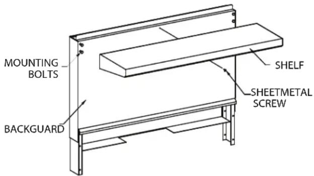
text_image
MOUNTING BOLTS BACKGUARD SHELF SHEETMETAL SCREWBackguard With High Shelf Or Salamander Mounting Instructions
- Rear of the range must be easily accessible.
- Please refer to the installation instructions included with the salamander for further instructions on these units.
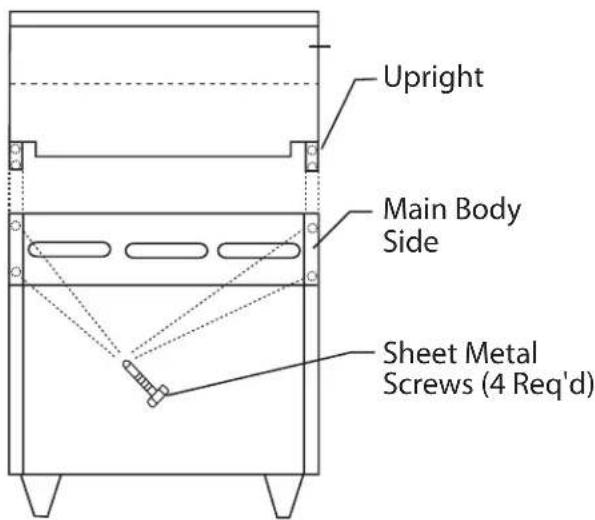
- Place the backguard or high shelf on the rear of the range, slipping the support brackets into the openings in the main body sides.
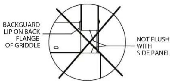
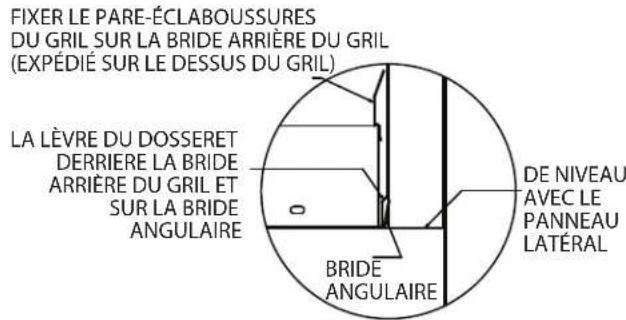
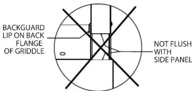
- For ranges with griddles, care must be taken when mounting the backguard or high shelf. The front panel of the stainless steel backguard or high shelf has an extruding lip at the bottom. This lip must NOT go over the griddle back splash, if it does the backguard will not fit properly and the range will not flue properly. Refer to illustration for proper installation.
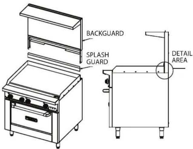
text_image
BACKGUARD SPLASH GUARD DETAIL AREACorrect Installation
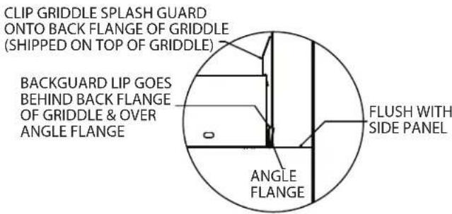
text_image
CLIP GRIDDLE SPLASH GUARD ONTO BACK FLANGE OF GRIDDLE (Shipped ON TOP OF GRIDDLE) BACKGUARD LIP GOES BEHIND BACK FLANGE OF GRIDDLE & OVER ANGLE FLANGE ANGLE FLUSH WITH SIDE PANELIncorrect Installation
text_image
BACKGUARD LIP ON BACK FLANGE OF GRIDDLE NOT FLUSH WITH SIDE PANEL- Securely fasten the support brackets to the burner box sides with (4sheet metal screws provided).
text_image
Upright Main Body Side Sheet Metal Screws (4 Req'd)Ventilation Air
The following notes are intended to give general guidance. For detailed recommendations, refer to the applicable code(s) in the country of destination. These appliances shall be installed in a room with sufficient ventilation to prevent the occurrence of hazardous concentrations of combustion by-products.
The room containing the appliance is required to have a permanent vent. The minimum effective area of the vent is related to the maximum rated heat input of the appliance and shall be 4.5 cm^2 per kW in excess of 7 kW.
Proper ventilation is critical for optimum performance. The ideal method of ventilating open-top equipment is the use of a properly designed canopy that should extend six inches (152 mm), beyond all sides of the appliance(s) and six feet, six inches (1981 mm) above the floor.
Air vents should be of such a size as to compensate for the effects of any extract fan in the premises. A strong exhaust will create a vacuum in the room. For an exhaust vent to work properly, replacement air must be equal to the amount of air exhausted. An imbalance between exhaust and replacement air can cause degradation in the appliance's performance.
All gas burners and pilots need sufficient air to operate. Large objects should not be placed in front of the appliance(s) that would obstruct the flow of air into the front.
Statutory Regulations
In European countries, installation must be carried out by a competent person and in accordance with the relevant regulations, codes of practice and the related publications of the country of destination.
In the United States, the installation must conform to the National Fuel Gas Code ANSI Z223.1, or latest edition, NFPA No.54 - latest edition/or local code to assure safe and efficient operation. In Canada, the installation must comply with CSA B149.1 and local codes.
Australia Specific Clause
This appliance must be installed in accordance with the manufacturer's instructions, local gas fitting regulations and requirements of AS 5601 installation code. All burner adjustments and setting should be made by a qualified gas technician.
Electrical Connection Settings (Where Applicable)
IMPORTANT- This appliance must be electrically grounded in accordance with local codes, or in the absence of local codes with the National Electrical Code.
220/240 Volt Convection Oven Models
When the appliance is ordered and equipped for 220/240 volt operation, the supply line must be connected to the wiring terminations located inside the terminal box at the rear of the appliance.
For ease of attaching the supply line, there is a removable cover on the terminal box.
Permanent connection to the electrical service must comply with local codes, or in the absence of local codes, with the national electrical code.
Gas Connection
The local gas authority should be consulted at the installation planning stage in order to establish the availability of an adequate supply of gas and to ensure that the meter is adequate for the required flow rate. The pipe work from the meter to the appliance must be an appropriate size.
All fixed (non-mobile) appliances MUST be fitted with an accessible upstream gas shut off valve as a means of isolating the appliance for emergency shut off and for servicing. A union or similar means of disconnection must be provided between the gas-cock and the appliance.
A manually operable valve must be fitted to the gas supply to the kitchen to enable it to be isolated in an emergency. Wherever practical, this shall be located either outside the kitchen or near to an exit in a readily accessible position.
Where it is not practical to do this, an automatic isolation valve system shall be fitted which can be operated from a readily accessible position near to the exit.
In locations where the manual isolation valve is fitted or the automatic system can be reset this notice MUST be posted:
"ALL DOWNSTREAM BURNER AND PILOT VALVES MUST BE TURNED OFF PRIOR TO ATTEMPTING TO RESTORE THE SUPPLY. AFTER EXTENDED SHUT OFF, PURGE BEFORE RESTORING GAS."
Installation Notes
Before assembly and connection, check gas supply.
A. The type of gas for which the unit is equipped is stamped on the rating plate located behind the lower front panel. Connect a unit stamped "NAT" only to natural gas; connect one stamped "PRO" only to propane gas.
B. If it is a new installation have the gas authorities check meter size and piping to assure that the unit is supplied with the necessary amount of gas pressure required to operate the unit.
C. If it is additional or replacement equipment have the gas authorities check pressure to make certain that existing meter and piping will supply fuel to the unit with no more than 0.15 Kpa pressure drop.
D. Make certain new piping and connections have been made in a clean manner and have been purged so that piping compound, chips, etc. will not clog pilots, valves or burners. Use pipe joint compound approved for natural and liquefied petroleum gases.
NOTE: Gas pressure should be checked when the unit is installed with all other equipment on the same line turned on. The operating manifold gas pressure must be the same as that specified on the rating plate. If necessary, pressure adjustment may be made at the pressure regulator supplied with the appliance.
The appliance pressure regulator provided by the factory is pre-set to the correct manifold pressure. The manifold pressure may require verification and adjustment at the installation. Allow at least one burner to be ignited and operating while checking manifold pressure at the test spigot located on the appliance manifold, and adjust the appliance pressure regulator accordingly.
The appliance and its individual shut-off valve must be disconnected from the gas supply piping system during any pressure testing of that system where pressures are in excess of 1/2 PSIG (3.45kPa.)
Final Preparation
NOTE: Your new range has a plastic coating to help protect the finish from scratches during shipping. This protective plastic film should be peeled off prior to starting the range.
Optional Interconnect Gas Kit # 4523975
To interconnect range mount salamanders with range
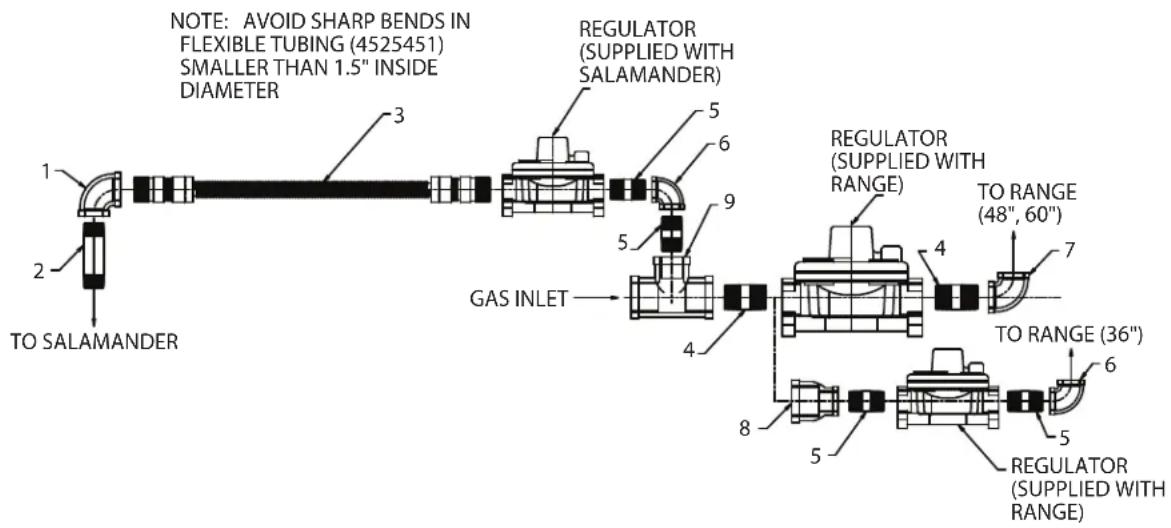
The GF series Garland range can be equipped with a range mount gas salamander. Salamanders can be plumbed independently or be interconnected with the range. See Drawing for various options for mounting onto a 36" (900mm,) a 48" (1200mm) or a 60" (1500mm) range.
Optional Interconnect Gas Kit # 4523975
text_image
NOTE: AVOID SHARP BENDS IN FLEXIBLE TUBING (4525451) SMALLER THAN 1.5" INSIDE DIAMETER 1 2 TO SALAMANDER 3 5 6 9 5 GAS INLET 4 8 5 REGULATOR (SUPPLIED WITH SALAMANDER) REGULATOR (SUPPLIED WITH RANGE) TO RANGE (48", 60") 7 TO RANGE (36") 6 REGULATOR (SUPPLIED WITH RANGE)| ITEM | PART # DESCRIPTION | QUANTITY | |
| 36" 48", 60" | |||
| 1 GO | 1474-9 Reducng Elbow 3/4" NPT X 1/2" NPT 1 1 | ||
| 2 GO | 1896-2 Nipple 1/2" NPT x 3-1/2" 1 1 | ||
| 3 | 4525451 72" Flexible S.S. Tub Assy | 1 | 1 |
| 4 | 076029-204 Nipple 1" NPT x 2" | 1 2 | |
| 5 | G01738-14 Nipple 3/4" NPT x 2" | 4 2 | |
| 6 GO | 1474-5 90° Elbow 3/4" NPT 2 1 | ||
| 7 | 076029-171 90° Elbow 1" NPT | 1 | |
| 8 | 2437100 Reducing Adapter 1" NPT – 3/4" NPT | 1 | |
| 9 | 3012800 Tee 1" NPT x 1" NPT x 3/4" NPT | 1 | 1 |
| 10 | 4523975 Restaurant Universal Interconnect Kit | * | * |
TESTING AND ADJUSTMENT
Testing
All fittings and pipe connections must be tested for leaks. Use approved gas leak detectors, soap solution or equivalent, checking over and around all the fittings and pipe connections. DO NOT USE A FLAME! Accessibility to all gas lines and fittings require that valve panel(s) lower front panel(s), and/or oven rack(s) be removed. It may be necessary to remove, or at least raise and securely prop griddle(s), hot top(s), and/or top grate(s). All parts removed, (including fasteners), should be stored safely for re-installation.
-
Be sure that all valves and thermostats are in the "OFF" position.
-
Turn on the main gas supply valve. Light all top section pilots.
- Leak test all valves and fittings as described at the beginning of this section. Correct any leaks as required and recheck.
- Light the oven pilot.
- Set the oven thermostat to maximum. Leak test all valves and fittings as described at the beginning of this section. Correct any leaks as required and recheck.
- Shut off all valves and set thermostat dials to "OFF" or lowest position. All units are tested and adjusted at the factory, however, burners and pilots should be checked upon installation and adjusted if necessary.
OPERATION
Flame Failure Technology
The Garland GF series gas range has total flame failure (also referred to as flame safety) technology. It is a simple system that monitors the existence of a gas flame. It can be used on most gas appliances and will turn off the gas supply to any burner using the system when a pilot ignition flame is not present.
Flame failure systems have been available for many years and it is the "CE" agency standard accepted for European gas appliance approvals. In North America this technology is gaining greater acceptance and various levels of government are making it mandatory in schools and other government institutions.
How Flame Failure Technology Works
For gas restaurant ranges, there are three principles at work in a flame failure system, they are a safety valve, the thermocouple and the pilot.
Safety Valve
The SIT control used on the new Garland series of restaurant ranges operates both as the mechanism to control the oven temperature (thermostat) and the safety valve for the flame failure system. This valve contains a magnet which when electrically charged, will hold a check valve in an open state allowing for gas to flow through the valve as required by either the pilot or main burner. The magnet is charged through an electrical signal sent from the thermocouple when a flame is present. When no flame is present, no signal is sent and the magnet releases closing the check valve. Because no gas can flow through the valve if the pilot is not burning, no gas can build up, decreasing the risks of any safety conditions.
Thermocouple
The thermocouple is positioned so that the tip of the thermocouple comes into contact with the pilot flame when lit. When exposed to a flame, a properly functioning thermocouple produces a small electrical signal measured in millivolts. This signal is transferred through the electrical wire connecting the thermocouple to the safety valve in the SIT control, and to the magnet inside the valve thereby energizing it. Again, when the magnet is energized, it is able to hold a check valve in an open state allowing gas to flow through the valve to the burner(s) and pilot(s). If the pilot goes out then the generation of millivolts stops and the magnet in the safety valve releases to close off the supply gas.
Pilot
The pilot provides the flame that the thermocouple uses to generate millivolts. When all three of the above components are placed together a Flame Failure system is created.
The above principles apply no matter what section of the range is using flame failure technology. When operating open top burners or hot tops the hi-lo valve also acts as a safety valve in the system. The same SIT thermostat as in the oven section of the range is used on flat griddle models.
Burner Operation
Caution: In the event that a binding or malfunctioning valve, or thermostat control is observed DO NOT light the pilots or continue operation until an authorized service technician has inspected the appliance. Failure to do so may result in injury.
Open Top burners
Lighting
-
Push in the valve knob, and turn it counter clockwise to the ignition "★" position.
-
While holding the valve knob fully in, light the pilot burner with a match or BBQ ignition device.
Note: On ranges equipped with electric spark igniters, press the igniter button and check that the pilot lights. Should burner ignition fail within 4 seconds, turn the burner valve off and repeat steps 1 through 2. If ignition continues to fail, consult the factory authorized service agency.
- When the pilot is lit continue to hold the valve knob fully in for at least 30 seconds, then release it. If the pilot goes out, wait for (5), minutes, then repeat from step 1.
- When the pilot remains lit, push the valve in again and turn it counter-clockwise to the desired flame setting position, lighting the burner.
Shut Down
- To turn the burner off and still have the pilot remain on, turn the dial to the ignition "position."
- To turn the burner and pilot off, turn the dial to the circular "OFF" symbol. The safety device will disengage within 60 seconds.
Hot Tops and Front-Fired Target Tops
Lighting
-
Push in the valve knob, and turn it counter clockwise to the ignition "position.
-
While holding the valve knob fully in, press the igniter button and observe if the pilot lights. If it does not light, repeatedly depress the igniter button until it does.
Note: On ranges equipped with electric spark igniters, press the igniter button and check if the pilot lights. Should burner ignition fail within 4 seconds, turn the burner valve off and repeat steps 1 through 2. If ignition continues to fail, consult the factory authorized service agency.
- When the pilot is lit continue to hold the valve knob fully in for at least 30 seconds, then release it. If the pilot goes out, wait for (5), minutes, then repeat from step 1.
- When the pilot remains lit, push the valve in again and turn it counter-clockwise to the desired flame setting position, lighting the burner.
- For low flame or simmer push in the valve knob and turn it counter-clockwise to the low flame position.
- Surface plates are capable of reaching very high temperatures, solid hot tops 380C(716F) front -fired
target tops 585C(1085F).
Shut Down
- To turn the burner off and still have the pilot remain on, turn the dial to the ignition "position."
- To turn the burner and pilot off, turn the dial to the circular "OFF" symbol. The safety device will disengage within 60 seconds.
Ovens (Standard)
Lighting
- Lower front kick panel below oven door, raise oven hearth bottom for easy access to oven pilot.
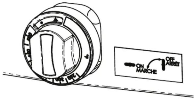
- Turn oven control knob (figure 1) to “” position and then push in to engage the flow of gas through the safety device to the pilot.
Figure 1
text_image
ON MARCHE OFF ARRET- While holding knob in, light pilot with a match/BBQ lighter or use the spark ignition (if provided) to spark ignite pilot.
- Continue to hold knob in for 15 seconds after ignition, then release. Pilot should remain lit.
- If pilot burner fails to light or does not stay lit, wait 5 minutes and repeat steps 2 through 4.
- Replace hearth or close kick panel, then turn oven thermostat to desired cooking temperature.
- To shut down main burner turn control knob (figure 1) to
" "position.
Warning: Use caution when opening the oven door while it is in use. Hot air or steam may cause injury.
Shut Down
If pilot shut down is required push in oven thermostat knob and turn to "symbol. The system will disengage with in 60 seconds.
Convection Ovens
The forced air range oven consists of a food preparation chamber completely sealed from the combustion area. This eliminates the possibility of contamination from flue products and permits an efficient method of circulating the heated air within the cooking chamber.
During the cooking process in a conventional oven, a vapor barrier and a layer of "cool" air covers the exposed area of the product. In a forced air oven, the fan pushes the heated air over and around the product, sweeping away the vapor barrier and cool air, permitting faster heat penetration. This action permits the use of lower temperatures and shorter cooking times.
The rule of thumb for determining the cooking temperature is to reduce the set temperature by approximately 80^ F, ( 28^ C), from that which you would set in a conventional oven. The product should be checked at a point midway in the time required in a conventional oven.
Lighting
- Lower front kick panel below oven door.
- Push and hold in oven thermostat control valve knob (figure 1) and turn it counter clockwise to the ignition position "★"
- While holding knob fully in depress the red igniter button and observe that the pilot flame is lit. If it does not light, repeatedly depress the igniter button until it does.
Note: On ranges equipped with electric spark igniters, press the igniter button and check if the pilot lights. Should burner ignition fail within 4 seconds, turn the burner valve off and repeat steps 1 through 2. If ignition continues to fail, consult
the factory authorized service agency.
- When the pilot is lit, continue to hold the valve knob fully in for 15 seconds, then release it. If the pilot goes out, wait for five (5) minutes, then repeat steps 2 to 4.
Start Up
- Set the power switch to the "COOK" position.
- Turn the thermostat to the desired setting.
Cool down
- Turn the oven valve knob to the “” position this will prevent the main oven burner from cycling on. (figure 1).
- Turn the thermostat to its lowest setting.
- Open the oven door.
Warning: Use caution when opening the oven door while it is in use. Hot air or steam may cause injury.
- Set the power switch to the "COOL DOWN" position.
- Once the oven has cooled turn the power switch to off and close the oven door.
Shut Down
- If pilot shut down is required push in oven thermostat knob turn to "symbol. The system will disengage with in 60 seconds.
- Power switch should be in the off position.
Operating Suggestions
The motor in your range convection oven is maintenance free since it is constructed with self-lubricating sealed ball bearings. It is designed to provide durable service when treated with ordinary care. We have a few suggestions to follow for the care of your motor.
A. When the motor is operating, it cools itself internally by air entering the rear of the motor case, provided proper clearance has been allowed.
B. Since the blower wheel is in the oven cavity it is at the same temperature as the oven. If the motor is stopped while the oven is hot, the heat from the blower wheel is
conducted down the shaft and into the armature of the motor. This action could shorten motor life.
C. We recommend, at the end of the bake or roasting period, when the oven will be idle for any period of time or before shutting down completely, that the doors be left open, and by use of the cool-down position on the fan switch, the fan continues to run for at least 20 minutes. The "FAN" should never be turned "OFF" when the oven section is in use.
D. All convection oven model units have a controllable moisture vent. The vent control is a sliding cover inside the oven cavity. Sliding the vent from left to right will increase or decrease the amount moisture inside the oven during cooking. Dryness or moisture of the finished product will dictate the setting of the vent. To speed up pre-heat time close the vent during preheat.
Thermostat Controlled Griddles
See griddle seasoning before use.
- For general thermostat griddle lighting instructions please refer to the section entitled "OVEN (STANDARD)" above. (Steps 2 though 7)
- Pilots should be lit though the front panel with an extend match or long BBQ lighter. If necessary the front panel of the range can be removed to allow the griddle plates to be raised at the front, block securely.
- Light pilots located at the front left side of each burner
- The sensing bulbs must be fully inserted into their individual holders, which are located on the underside of the griddle. To check griddle burner flame set the thermostat to its maximum setting and then return to pilot.
- If the griddle has been raised to light the pilots, lower carefully into position, being very careful not to leave any part of the capillary tube in the burner compartment. Replace the front panel of the range.
- Surface temperature of solid griddle top is capable of reaching at least 265C (509 F).
Caution: Only authorized service technicians should be removing thermostat control knobs. In the event the thermostat temperature knob has been removed, the set screw must line up with the hole on the thermostat control dial.
Griddle/Broiler
See griddle seasoning before use.
Lighting
1 Push in the valve knob, and turn it counter clockwise to the ignition "position.
2 While holding the valve knob fully in, press the igniter button and check if the pilot lights. If it does not, repeatedly depress the igniter button until it does.
Note: On ranges equipped with electric spark igniters, press the igniter button and check that the pilot lights. Should burner ignition fail within 4 seconds, turn the burner valve off and repeat steps 1 through 2. If ignition continues to fail,
consult the factory authorized service agency.
- When the pilot is lit continue to hold the valve knob fully in for at least 30 seconds, then release it. If the pilot goes out, wait for (5), minutes, then repeat from step 1.
- When the pilot remains lit, push the valve in again and turn it counter-clockwise to the desired flame setting position, lighting the burner.
- For low flame or simmer push in the valve knob and turn it counter-clockwise to the low flame position.
- Surface Temperature of solid griddle top is capable of reaching at least 380C (716 F).
Shut Down
- To turn the burner off and still have the pilot remain on, turn the dial to the ignition "position."
- To turn the burner and pilot off, turn the dial to the circular "OFF" symbol. The safety device will disengage within 60 seconds.
Range Shut down
- Turn all valves to the "OFF" position.
- If the unit is to be shut down for an extended period of time, close the in-line gas valve.
PRODUCT APPLICATION INFORMATION
General
The range is the workhorse of the kitchen because of its versatility. Most frequently used in small applications, such as cafes, schools, church kitchens, firehouses, and small nursing homes where demands are less taxing. As a general rule of thumb, one four to six burner range with a hot top will be adequate for a restaurant seating 30 to 35.
The top of the range is designed for flexibility and the preparation of numerous medium volume types of products. It may be equipped with two, or even three different types of tops and burners, depending on the menu needs. An operation that cooks to order, or uses the range primarily as back-up will find that open burners will suit most of their needs.
Preparation of soups, stocks, or sauces is done on a hot top where slow, even cooking is desirable.
Heating larger quantities of food can be done more efficiently than heating small quantities. Pots and pans should be covered whenever possible to reduce energy consumption.
High acid sauces, such as tomato should be cooked in stainless steel rather than aluminum to avoid chemical reaction. Light colored sauces such as Alfredo may be discolored by the use of aluminum, especially if stirred with a metal spoon or whip. Saltwater shellfish may pit aluminum pots if they are frequently used for this purpose.
Use appropriately sized pots and pans to fit each burner. Do not allow pots to overhang plate rail.
Crumb Trays
In the event of a grease fire in the crumb tray, call a service technician to inspect for possible damage to components. Do not continue to operate unit until inspected by authorized service agent.
NOTE: Many parts of the commercial range are raw steel. Hot tops, griddles, springs, door hooks etc., can react with moisture forming rust. This occurrence is normal and not considered a defect. Clean with a stainless steel or fiber pad. A light coating of cooking oil may be applied.
CAUTION: DO NOT SPRAY AEROSOLS IN THE VICINITY OF THIS APPLIANCE WHILE IT IS IN OPERATION.
Open Burners
The most traditional uses of open burners are sautéing, pan frying, and small stock pot work. Short-term cooking is the most efficient use for the open burner. Pans should cover as much of the grate as possible to minimize heat loss. The maximum stock pot size to be used on an open burner is 12 inches, (305mm), diameter. Use a pan size large enough to contact all of the grate supports (minimum 6", 150mm). Open burners should be turned off when not in use to conserve energy. Leaving a flame burning is of no advantage since the heat is instantaneous.
Hot Tops
Use of the solid hot tops is recommended where long-term stock pot cooking is required for soups, sauces or stock. Pots can be placed anywhere on the hot tops. Recommended pre-heat time is 30 minutes. This will ensure that the casting is thoroughly saturated with heat. Pots have should flat bottoms for maximum surface contact. Warped or dented pots will not transfer heat evenly, wasting energy and resulting uneven cooking patterns. During slow periods, it is advisable to lower the burner setting to conserve energy.
Seasoning
Griddle
A. Remove all factory applied protective material by washing with hot water, mild detergent or soap solution.
B. Apply a thin coat of cooking oil to the griddle surface, about one ounce per square foot of griddle surface. Spread over the entire griddle surface with a cloth to create a thin film. Wipe off any excess oil with a cloth.
C. Light all burners, set at the lowest possible setting. Some discoloration will occur when heat is applied to steel.
D. Heat the griddle slowly for 15 to 20 minutes. Then wipe away oil. Repeat the procedure 2 to 3 times until the griddle has a slick, mirror like finish.
IMPORTANT: Do not set to a high position (on valve control) or 450° (on thermostat control) during "break-in" period.
NOTE: Steel griddle surface will tone (blue discoloration) from heat. This toning will not diminish function or operation and it is not a defect.
The griddle will not require reseasoning if it is used properly. If the griddle is over heated and product begins to stick to the surface it may be necessary to repeat the seasoning process again. If the griddle is cleaned with soap and water it will be necessary to reseason the griddle surface.
Cast Iron top Grates
First, remove the cast iron top grates from the range. Wash the cast iron top grates thoroughly with a mild soap and warm water. Dry the cast-iron top grates thoroughly with a clean cloth. Immediately after drying, season the top grates lightly with a non-toxic oil, (Liquid vegetable oil or Pam spray oil) WARNING; DO NOT SEASON THE TOP GRATES WHILE ON THE RANGE TOP! Seasoning grates on the range top over an open flame could cause a flash fire. After seasoning, replace the top grates onto the range. Turn all the range top sections "ON LOW". Allow the top sections to burn in this manner for at least 20 minutes before using pots or pans on the top grates. SEASONING OF THE TOP GRATES WILL BE REQUIRED WHENEVER THEY HAVE BEEN CLEANED. FAILURE TO SEASON GRATES WILL CAUSE RUSTING.
Stainless Steel
For routine cleaning, wash with a hot water and detergent solution. Wash just a small area at a time or the water will evaporate leaving the chemicals behind causing streaking.
Rinse the washed area with a clean sponge dipped in a sanitizing solution and wipe dry with a soft clean cloth before it can dry.
Use a paste (of water and a mild scouring powder) if you have to, but never rub against the grain. All stainless steel has been polished in one direction. Rub with the polish lines to preserve the original finish. Then thoroughly rinse as before.
To prevent fingerprints there are several stainless steel polishes on the market that leave an oily or waxy film. Do not use on surfaces that will be in contact with food.
Stainless steel may discolor if overheated. These stains can usually be removed by vigorous rubbing with a scouring powder paste.
Use only stainless steel, wood or plastic tools if necessary to scrape off heavy deposits of grease and oil. Do not use ordinary steel scrapers or knives, as particles of the iron may become imbedded and rust. NEVER USE STEEL WOOL.
Either a typical bleach solution or hot water can be used to sanitize stainless steel.
Oven Interior (Porcelain Enamel)
NOTE: Disconnect line cord (if applicable) from power supply before cleaning or servicing.
-
Before cleaning oven interior, remove all oven racks and guides (if "RC" base). Oven racks and guides can be cleaned with a mild soap and warm water or run through dish washer.
-
The porcelain interior can be cleaned with oven cleaners such as "Easy Off, or "Dow Oven Cleaner".
Follow product manufacturer's instructions for proper use.
Open Top Burners
Cleaning of the range top burner is a simple procedure, and, if done at regular intervals will prolong the life of the range and ensure good flame characteristics.
- The most common problem with open burner ranges is spillage. Once the burner ports are partially plugged with food, the air-to-gas mixture is disturbed and results in an inefficient burner.
- Wipe any spills as they occur.
- Grids and trays should be removed daily, washed, rinsed and dried thoroughly.
MAINTENANCE AND CLEANING Continued
- Use a wire brush to clean the ports of the burners. Ignite and check for clogged holes.
- If any clogged holes are apparent, the burner should be lifted out and brushed inside and out with a small Venturi brush. Each port on the burner itself should be cleaned with a properly sized wire or thumb drill. Wash with soap and hot water if grease is observed on the burners. Dry thoroughly.
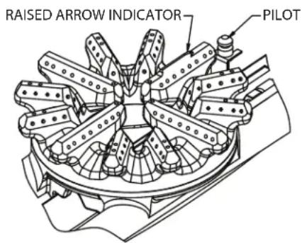
- When reinstalling the open top burner head be sure the burner ports are lined up correctly to the pilot. On the cast burner head there is a raised indicator arrow to ensure the burner is installed correctly.
text_image
RAISED ARROW INDICATOR PILOT- If an abnormal flame appears around the edges, it is usually a sign of grease or dirt in the throat of the burner. Remove the burner venturi (main body that the burner heads sit on) to access the air shutter opening. Remove grease and dirt from the air shutter area carefully. Do not adjust the shutter setting. The air shutter allows the proper amount of air to mix with the flow of gas coming in from your valve/thermostat orifice and should not be adjusted unless by a licensed gas fitter technician.
Cast Iron Top & Grates
Cast iron top and grate(s) can be cleaned with mild soap and warm water. For baked on material, a wire brush can be used. Dry thoroughly. Lightly coat with vegetable oil to help prevent rust from forming.
Hot Tops and Front-Fired Target Hot Tops
While the surface is still slightly warm, wipe down with a clean burlap cloth. Burnt on spillage should be scraped off. If necessary, remove the plate and wash in a sink with soap and hot water. Dry thoroughly. In damp climates, wipe down with a light coating of oil to prevent rusting. Avoid excessive use of water as this could damage the surface and the controls below.
CAUTION: Do not use water on top plates while they are hot or Do not use ice to cool plates.
NOTE: Hot top and front-fired target hot top surface will "tone" (blue/brown discoloration) from heat. This toning will not diminish function or operation and is not a defect.
Griddle
To produce evenly cooked, browned griddle products, keep griddle free from carbonized grease. Carbonized grease on the surface hinders the transfer of heat from the griddle surface to food product. This results in uneven browning and loss of cooking efficiency, and worst of all, carbonized grease tends to cling to grilled foods, giving them a highly unsatisfactory and unappetizing appearance. To keep the griddle clean and operating at peak performance, follow these simple instructions:
A. AFTER EACH USE clean griddle thoroughly with a grill scraper or spatula. Wipe off any excess debris left from cooking process.
B. ONCE A DAY clean griddle surface with a grill brick and grill pad. Remove grease container and clean thoroughly, in the same manner as any ordinary cooking utensil.
C. ONCE A WEEK clean griddle surface thoroughly. If necessary, use a grill stone or grill pad over the griddle surface. Rub with grain of the metal while still warm. A detergent may be used on the plate surface to help clean it, but care must be taken to be sure it is thoroughly removed. After removal of detergent, the surface of the plate should be covered with a thin film of oil to prevent rusting. To remove discolorations, use a non-abrasive cleaner. Before re-using, the griddle must be reseasoned. Keep griddle drain tube to grease container clear at all times.
CAUTION This griddle plate is steel, but the surface is relatively soft and can be scored or dented by careless use of a spatula.
Be careful not to dent, scratch, or gouge the plate surface. This will cause food to stick in those areas. Also, note, since this is a steel griddle if a light coating of oil is not always present rust will develop on exposed and uncoated areas.
Garland INSTRUCTIONS D'INSTALLATION ET D'UTILISATION SÉRIE GARLAND GF SENTRY CUSINIÈRES DE RESTAURANT À GAZ




POUR VOTRE SÉCURITÉ: NE PAS STOCKER NI UTILISER D'ESSENCE OU D'AUTRES VAPEURS OU LIQUIDES INFLAMMABLES À PROXIMITÉ DE CET APPAREIL OU DE TOUT AUTRE APPAREIL
AVERTISSEMENT UNE INSTALLATION, DES RÉGLAGES, DES MODIFICATIONS, DES RÉPARATIONS OU UN ENTRETIEN MAL FAITS PEUVENT CAUSER DES DOMMAGES MATÉRIELS, DES BLESSURES OU LA MORT. LIRE SOIGNEUSEMENT LES INSTRUCTIONS D'INSTALLATION, D'UTILISATION ET D'ENTRETIEN AVANT D'INSTALLER OU DE RÉPARER L'ÉQUIPEMENT.
1177 Kamato Road, Mississauga, Ontario L4W 1X4
CANADA
INFORMATIONS IMPORTANTES .....22
DIMENSIONS ET SPÉCIFICATIONS .....24
INFORMATIONS D'APPLICATION DES PRODUITS ....39
Généralités ....39
text_image
FICHE ÉLECTRIQUE (LE CAS ÉCHÉANT) 3-1/2" [89mm] 2-1/4" [57mm] [876mm] 27-1/4" [692mm]34-1/2" 5" [127mm]text_image
9-3/8" [238mm] 15-5/8" [396mm]text_image
12-1/8" [307mm] 18-3/8" [466mm] 51" [1290mm] DOSSERET STD AVEC ÉTAGÈRE HAUTE (EN OPTION) 39-3/8" [1000mm] DOSSERET À PROFIL BAS 13-7/8" [352mm] AJOUTER AVEC LA PORTE OUVERTE 31-1/8" [791mm] 3-7/8" [98mm] AJOUTER POUR FOUR À CONVECTION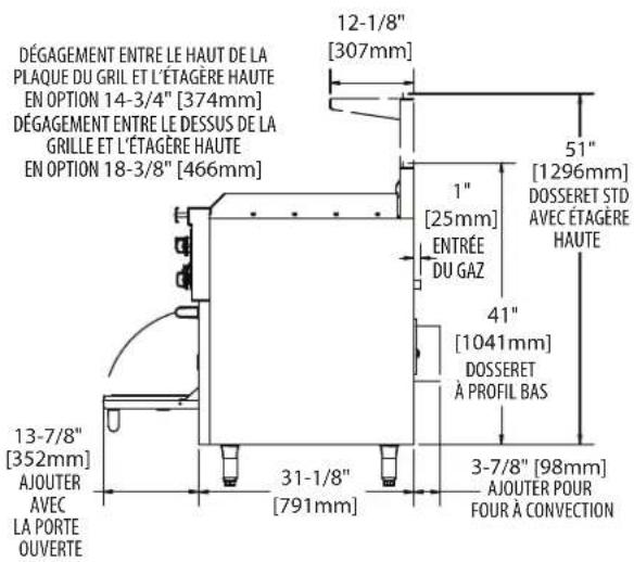
text_image
DÉGAGEMENT ENTRE LE HAUT DE LA PLAQUE DU GRIL ET L'ÉTAGÈRE HAUTE EN OPTION 14-3/4" [374mm] DÉGAGEMENT ENTRE LE DESSUS DE LA GRILLE ET L'ÉTAGÈRE HAUTE EN OPTION 18-3/8" [466mm] 12-1/8" [307mm] 51" [1296mm] DOSSERET STD AVEC ÉTAGÈRE HAUTE 1" [25mm] ENTRÉE DU GAZ 41" [1041mm] DOSSERET À PROFIL BAS 3-7/8" [98mm] AJOUTER POUR FOUR À CONVECTION 13-7/8" [352mm] AJOUTER AVEC LA PORTE OUVERTE 31-1/8" [791mm]Installation Correct
text_image
FIXER LE PARE-ÉCLABOUSSURES DU GRIL SUR LA BRIDE ARRIÈRE DU GRIL (EXPÉDIÉ SUR LE DESSUS DU GRIL) LA LÈVRE DU DOSSERET DERRIERE LA BRIDE ARRIÈRE DU GRIL ET SUR LA BRIDE ANGULAIRE BRIDE ANGULAIRE DE NIVEAU AVEC LE PANNEAU LATÉRALInstallation incorrecte
text_image
BACKGUARD LIP ON BACK FLANGE OF GRIDDLE NOT FLUSH WITH SIDE PANELInstructions Avant Installation
INFORMATIONS D'APPLICATION DES PRODUITS
Généralités
natural_image
Three identical stainless steel electric cookers with front-mounted fans and top heat sinks (no visible text or labels)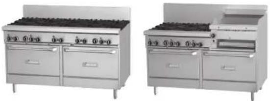
natural_image
Two identical stainless steel kitchen appliances, one with a front-mounted stove and the other with a mounted oven (no visible text or labels)




TODOS LOS MODELOS DE 24, 36, 48 Y 60 Pulgada
PARA SU SEGURIDAD:
NO ALMACENE O UTILICE GASOLINA U OTROS VAPORES O LÍQUIDOS INFLAMABLES EN LAS CERCANÍAS DE ESTE O CUALQUIER OTRO ARTEFACTO.
ADVERTENCIA:
1177 Kamato Road, Mississauga, Ontario L4W 1X4
CANADÁ
text_image
ENCHUFE ELÉCTRICO (DONDE APLIQUE) 3-1/2" [89mm] 2-1/4" [57mm] [876mm] 27-1/4" [692mm]34-1/2" 5" [127mm]| SerieAncho |
| GF24 600mm (23-5/8")* |
| GF36 900mm (35-1/2")* Mostrado |
| GF48 1200mm (47-1/4") |
| GF60 1500mm (59-1/2") |
| *Base de la estufa o parte superiorde las estufas modulares |
text_image
9-3/8" [238mm] 15-5/8" [396mm]Vista Lateral del Serie GF
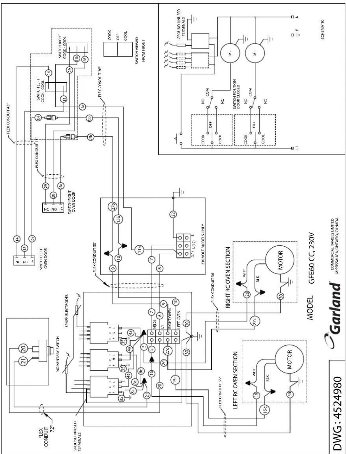
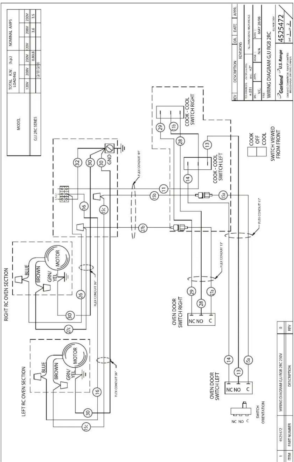
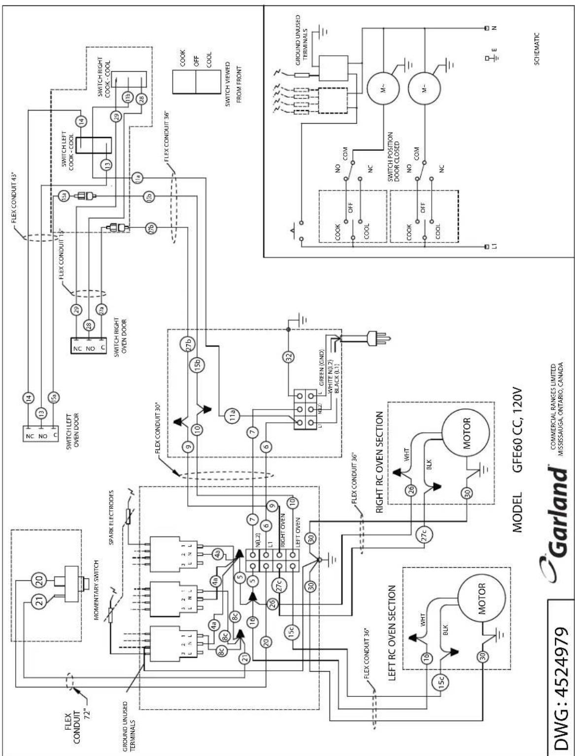
NOTE: Wiring Diagrams are also attached to the back of the range.
Schémas De Câblage
text_image
BLUE BROWN GRN/ YEL MOTOR 15c 30 16 FLEX CONDUIT 36°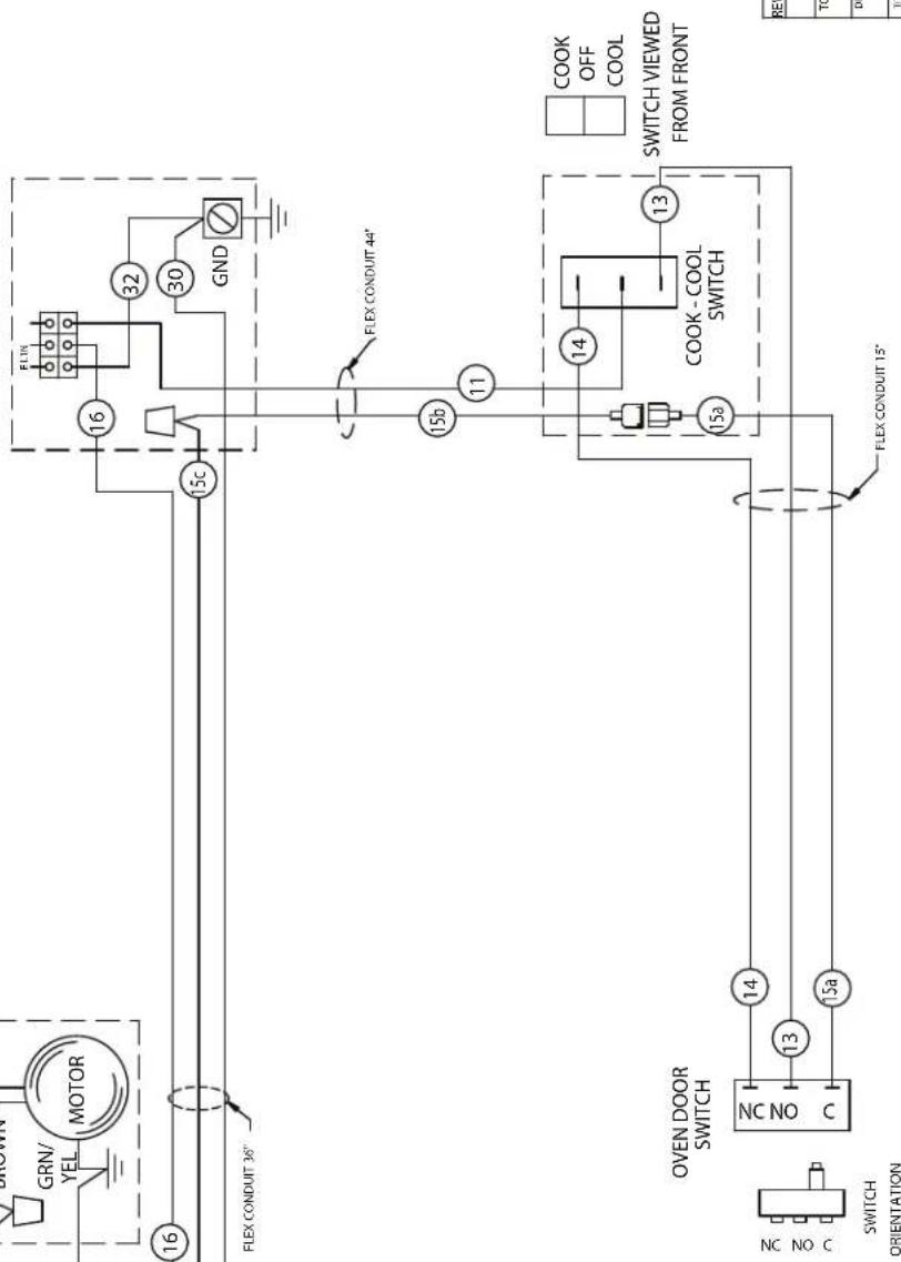
text_image
BROWN GRN/ YEL MOTOR 16 15c FLEX CONDUIT 3/8" FLEX CONDUIT 44" 15b 11 COOK - COOL SWITCH VIEWED FROM FRONT COOK OFF COOL 13 15a 14 15a 13 16 32 30 GND OVEN DOOR SWITCH SWITCH ORIENTATION| 1 | 4525471 | WIRING DIAGRAM G,U RGB LT 230V | |
| ITEM | PART NUMBER | DESCRIPTION |
| REV | DESCRIPTION | DR. | DATE | APPR. | ||
| REVISIONS | ||||||
| TOLERANCES ±.031 | AUG. ±2" | ALL DIMENSIONS ARE IN INCHES | ||||
| DR: V.C. | APPR. | SCALE : N/A | DATE : MAY 28/08 | |||
| TITLE: WIRING DIAGRAM G,U RGB LT GU RBO 230V | ||||||
| Garland U.S. RangeGARLAND COMMERCIAL RANGES LIMITEDMISSISSARGA, ONTARIO, CANADA | 4525471SHI 1 or 2 | |||||
text_image
RIGHT RC OVEN SECTION LEFT RC OVEN SECTION BLUE BROWN GRN/ YEL MOTOR 15c 30 16 FLEX CONDUIT 36° BLUE BROWN GRN/ YEL MOTOR 27c 30 26 FLEX CONDUIT 36° 15c 32 30 30 GND FLEX CONDUIT 4" 27b 15b 11 29 11b COOK - COOL SWITCH RIGHT OVEN DOOR SWITCH RIGHT NC NO C 28 27a 14 13 15a FLEX CONDUIT 15° COOK - COOL SWITCH VIEWED FROM FRONT COOK OFF COOL SWITCH ORIENTATION ONC NO C 14 13 15a ITEM PART NUMBER DESCRIPTION REV MODEL TOTAL K.W. (h.p.) LOADING NOMINAL AMPS 120V 208V 230V 20V 208V 230V G.U 2RC SERIES 0.80.8 3.6 3.5 (2/3) (2/B) REV DESCRIPTION DR. DATE APPR. REVISIONS TOLERANCES (INVERTIFIED) ±.031 ANG. ±2° ALL DIMENSIONS ARE IN INCHES DR.: APPR. SCALE : DATE : V.C. N/A MAY 28/08 TITLE: WIRING DIAGRAM G.U RGB 2RC Garland U.S. Range 4525472 SARLAND COMMERCIAL RANGE LIMITED MISSISSAUGA, ONTAIBO, CANADA SHT 1 OF 2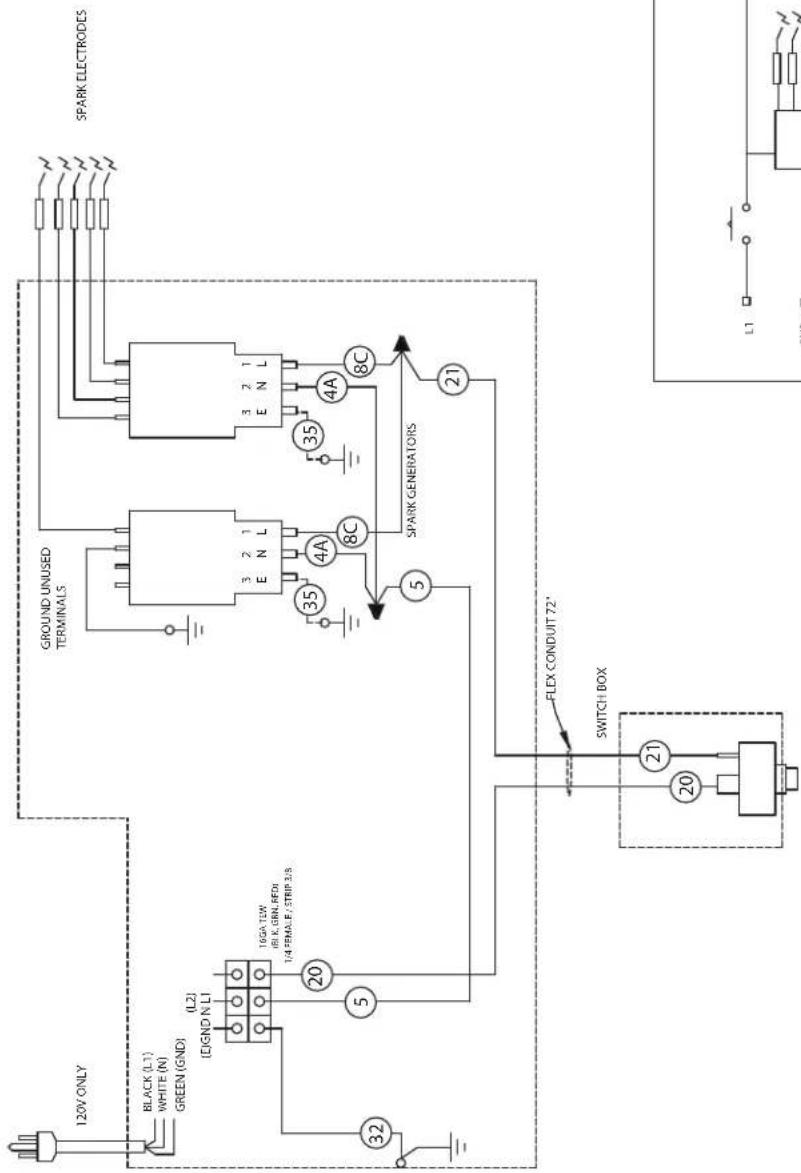
text_image
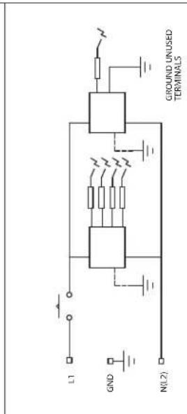
120V ONLY BLACK (L1) WHITE (N) GREEN (GND) (L2) (D)GND N L1 16GA T2W (6) K, GEN, RFDI 1/4 FEMALE / STRIP 3/5 20 5 32 21 GROUND UNUSED TERMINALS 3 2 1 E N L 35 4A 8C 35 4A 8C SPARK GENERATORS 21 FLEX CONDUIT 72° SWITCH BOX 20 21 SPARK ELECTRODES L1MODEL GFE ELECTRIC SPARK
Garland COMMERCIAL RANGES LIMITED MISSISSAUGA, ONTARIO, CANADA
DWG:4525255
text_image
L1 GND N(L2) GROUND UNUSED TERMINALSSCHEMATIC DIAGRAM
| MODEL | TOTAL K.W (h.p) LOADING | NOMIMAL AMPS | ||||
| 120V 208V 230V 120V 208V 230V | ||||||
| GFE 0.1 0.05 0.05 | ||||||
text_image
FLEX CONDUIT 72" MOMENTARY SWITCH SPARK ELECTRODES GROUND UNUSED TERMINALS 8c 8c 4a 4a 4a 5 16 20 26 27c 15c 30 FLEX CONDUIT 36" LEFT RC OVEN SECTION WHT BLK 30 MOTOR RIGHT RC OVEN SECTION 27c 26 BLK 30 MOTOR MODEL GFE60 CC, 120V FWREN (GND) WHITE N(1,2) BLACK (L1) FLEX CONDUIT 30' 9 10 11a 15b 15a 29 28 27a 28 27b 27b 15a 14 13 12 11a 10a FLEX CONDUIT 43" SWITCH LEFT OVEN DOOR FLEX CONDUIT 15" SWITCH RIGHT OVEN DOOR FLEX CONDUIT 36" COOK OFF COOL SWITCH VIEWED FROM FRONT COOK OFF COM COOL NC M~ SWITCH POSITION DOOR CLOSED COOK OFF COM M~ COOL NC L1 E N DWG: 4524979 GARLAND COMMERCIAL RANGES LIMITED MISSISSAUGA, ONTARIO, CANADA SCHEMAIC| MODEL | TOTAL K.W (h.p)LOADING | NOMINAL AMPS | ||||
| 120V 208V 230V | 120V 208V 230V | |||||
| GFE60 CC 120V 0.80 7.0 | ||||||
| (2/3) | ||||||