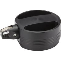
CTFP-40 - Pneumatic crimping press Panduit - Free user manual and instructions
Find the device manual for free CTFP-40 Panduit in PDF.


| Product Type | Pneumatic crimping press |
| Brand | Panduit |
| Model | CTFP-40 |
| Use | Crimping connector sleeves with cross-section 0.25 to 4 mm² onto wires |
| Dimensions (Diameter x Length) | 200 x 135 x 75 mm |
| Weight | Approximately 2.8 kg |
| Air supply | Filtered compressed air, pressure min. 4 bar, max. 6 bar |
| Air consumption | 0.2 liter per crimp at 5 bar |
| Acoustic emissions | L_pA < 70 dB(A) |
| Main components | Portable tabletop unit, air hose, pedal assembly, pedal, storage box, cap, finger guard, jaw |
| Provided accessory | Table mounting bracket |
| Operating temperature | 15°C to 35°C |
| Safety devices | Finger guard, automatic stop by air cutoff |
| Routine maintenance | Regular cleaning and lubrication |
| Recommended lubricant | CHEMPLEX 746 or equivalent |
| Spare parts | Available from Panduit (references listed in the manual) |
| Warranty | According to general terms and conditions; void if instructions not followed |
| Manufacturer | Panduit Corp., 18900 Panduit Drive, Tinley Park, IL 60487 USA |
| Technical service Europe | Tel.: +31 546 580 452, Email: emeatoolservicecenter@panduit.com |
| Technical service United States | Tel.: 1-800-777-3300, Email: techsupport@panduit.com |
Frequently Asked Questions - CTFP-40 Panduit
User questions about CTFP-40 Panduit
0 question about this device. Answer the ones you know or ask your own.
Ask a new question about this device
Download the instructions for your Pneumatic crimping press in PDF format for free! Find your manual CTFP-40 - Panduit and take your electronic device back in hand. On this page are published all the documents necessary for the use of your device. CTFP-40 by Panduit.
USER MANUAL CTFP-40 Panduit
BENCHMOUNT PNEUMATIC CRIMPING PRESS OPERATING INSTRUCTIONS
Original Instructions

TO REDUCE THE RISK OF INJURY, USER MUST READ INSTRUCTION MANUAL
NOTE: In the interest of higher quality and value, Panduit products are continually being improved and updated. Consequently, pictures may vary from the enclosed product.
For the most current version of this instruction manual, go to www.panduit.com.
Email:
USA Technical Support
Tel: 800-777-3300
Panduit Europe · EMEA Service Center
Tel: +31 546 580 452 - Fax: +31 546 580 441
Table of Contents
- SAFETY 2
1.1 Basic information 2
1.2 Symbols 2
1.3 Dangerousness of the machine 2
1.4 Designated use 2
1.5 Sources of danger 3
1.6 Work places 3
1.7 Safety devices 3
1.8 Permitted operators 3
1.9 Guarantee 3
- DESCRIPTION 4
2.1 Application 4
2.2 Components 4
2.3 Accessories 4
- OPERATION 5
3.1 Commissioning 5
3.2 Operation 5
- MAINTENANCE 6
4.1 Cleaning 6
4.2 Lubrication 6
- SPARE PARTS 7
- TECHNICAL DATA 8

Keep this for future use!
1. SAFETY
1.1 ....... Basic information
The basic prerequisite for ensuring safe use and continuous operation of the CTFP-40 is knowledge of and compliance with the safety instructions.
It is a question of your own safety!
All persons working with the CTFP-40 must observe the notes on safety.
In addition, rules and regulations that apply to the place of use, particularly regarding accident prevention, must be observed.
1.2 ....... Symbols
The following symbols will be used in these operating instructions:

indicates a possible accident or injury hazard and/or possible damage to the CTFP-40.

indicates notes on application.
1.3 ....... Dangerousness of the machine
The CTFP-40 has been constructed according to recognized technical safety regulations and has undergone a safety examination and received official acceptance.
It is equipped with safety devices.
However, operating error and misuse could present a danger to:
life and limb of the operator,
the machine.
The CTFP-40 should only be used:
for the designated application and
in perfect condition with regard to technical safety.
All persons involved with commissioning, operating and maintaining the CTFP-40, must:
be appropriately qualified and follow these operating instructions precisely.
1.4 ....... Designated use
The CTFP-40 is to be used exclusively for crimping wire-end ferrules with cross sections between #24 - 12 AWG (0,25 and 4,0mm^2 ). Under no circumstances should large metal parts or similar objects be introduced; the die set will be ruined.
Unauthorized amendments to the CTFP-40 are prohibited for safety reasons!
! Observation of all instructions and compliance with the prescribed operating conditions are part of the designated use.
1.5 ....... Sources of danger
The CTFP-40 must only be operated when the finger guard is screwed on. Only filtered compressed air with a maximum pressure of 6 bar can be used.
Disconnect the machine from the compressed air before working on the CTFP-40, during breaks and when the device is not in use. Do not pull on the compressed air tubing to disconnect.
1.6 ...... Work places
The following should be avoided for operation and storage:
- damp or dusty places,
- places which are subject to high levels of heat, direct sunlight or low temperatures: operating range: 59^ to 95^ (15 °C to 35 °C).
Protect the compressed air tubing from heat, oil and sharp edges.
1.7 ...... Safety devices
The CTFP-40 has a finger guard at the front as a contact safety device.
Under no circumstances should this be removed.
The CTFP-40 is stopped when disconnected from the compressed air supply.
1.8 ....... Permitted operators
Only authorized and instructed operators can work on the CTFP-40. The operator is responsible to third parties in the working area.
The owner must:
make the operating instructions available to the operator and
make sure that the operator has read and understood the instructions
1.9 ......... Guarantee
In principle, our "General terms of purchase and delivery" apply. These are available to the owner when the contract is concluded at the latest.
Guarantee and liability claims resulting from damage to personnel or property are inadmissible if the following points have been violated:
Non-designated use of the CTFP-40.
- Inappropriate working places.
- Inappropriate use and use which goes beyond that described in the operating instructions.
- Unauthorized structural amendments to the CTFP-40.
- Continued use of the CTFP-40 when a malfunction has been established.
- Repairs carried out inappropriately.
Only use original spare parts
2.DESCRIPTION
2.1 .... Application
The CTFP-40 is a pneumatic crimping tool for wire-end ferrules with a cross-section of between #24 - 12 AWG (0,25 and 4.0mm^2 ).
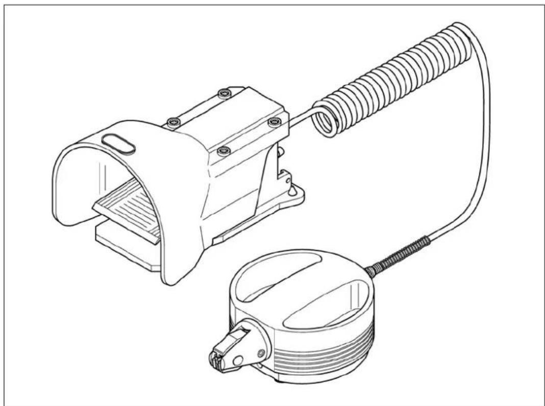
The CTFP-40 comprises a tabletop unit and a foot-operated switch. As both hands are free to insert the wire fitted with wire-end ferrules, the CTFP-40 is ideally suited to pre-confectioning cables.
2.2 Components
1 Tabletop unit
2 Compressed air tubing
3 Foot-operated switch
4 Switch
5 Storage compartment for wire-end ferrules
6 Head
7 Finger guard
8 Die set
2.3 Accessories
9 Table clamp
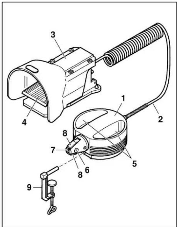
Figure 1 - Spare Parts
3. OPERATION
3.1 .... Commissioning
- Check whether finger guard (1) is present and is sitting firm.
- Check whether the die set (2) is free from foreign matter.
- Check whether the pneumatic tubing nuts (3) have been tightened firmly.
- Insert the table clamp (4) into the bore hole in the tabletop unit and screw tightly to the worktable.
- Check the compressed-air supply:

min. 4 bar, max. 6 bar filtered air
- Connect the free connection (5) on the foot switch to the compressed-air supply
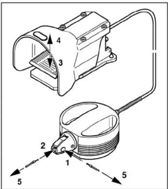
Figure 2 - Commissioning
3.2 ....... Operation
- Introduce stripped wire with wire-end ferrules already fitted, at the side (1) or from the front (2).
- Press the switch (3), the crimping process will be triggered.
- Release the switch (4), the crimped wire can be removed again (5).
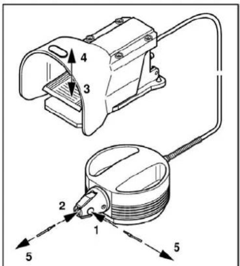
Figure 3 - Operation
4. MAINTENANCE

The CTFP-40 must be opened. Disconnect compressed air!
4.1 ....... Cleaning
- Unscrew hexagon socket screw (1).
Pull out the die set (2). - Clean die set (3) and lightly oil pivot (4).
- Push in die set (5).
- Tighten hexagon socket screw (6).
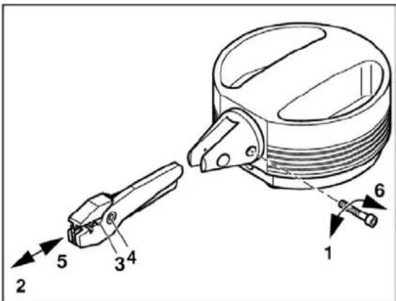
Figure 4 - Cleaning
4.2 Lubrication
- Unscrew the head (1).
- Remove the spring (2) and piston (3).
- Lubricate the two arms of the die set (4) (e.g. CHEMPLEX 746).
- Insert arms of the die set and spring.
- Insert head (5) and fasten fingertight.
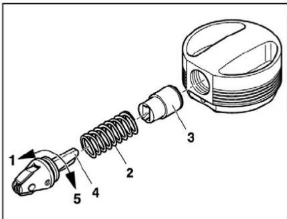
Figure 5 - Lubrication
5. SPARE PARTS
The following spare parts can be ordered with the appropriate Article No.
Address:
Panduit Corp.
16530 W. 163d St.
Lockport, IL 60441 U.S.A.
Tel. 1-800-777-3300
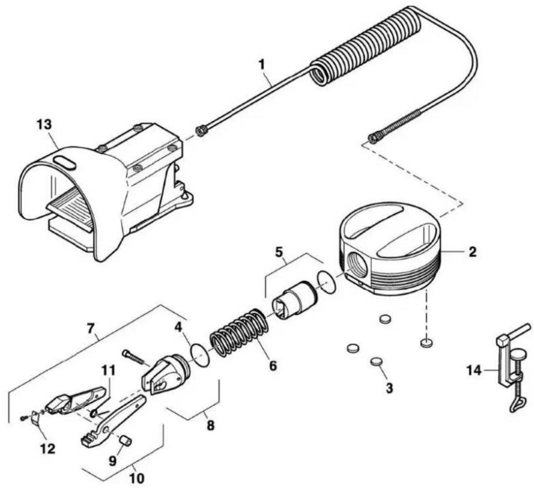
Figure 6 - Spare parts
| No. | Part | Article-No. | No. | Part | Article-No. |
| 1 | Compressed air tube | 008137 | 8 | Head part incl. screw and seal | 009691 |
| 2 | Body | 001564 | 9 | Axis | 001569 |
| 3 | Adhesive rubber pads | 001727 | 10 | Die Set | 009059 |
| 4 | Sealing ring | 001135 | 11 | Finger spring | 001556 |
| 5 | Piston | 005121 | 12 | Finger guard | 009749 |
| 6 | Spring | 001555 | 13 | Foot-operated switch | 005541 |
| 7 | Head complete | 008688 | 14 | Table clamp | 001551 |
6. TECHNICAL DATA
Instrument.. Pneumatic Crimper
Crimping range. #24 - #12 AWG (0,25 - 4,0 mm²)
Compressed-air connection min. 4 bar
max. 6 bar
Air consumption .0.2 liter / Crimping at 5 bar
Dimensions (diameter x length x height) 7.8" x 5.3" x 2.9"
(200 x 135 x 75 mm)
Weight approx. 6.2 lbs. (2.8 kg)
Acoustic pressure emissions LpA. < 70 dB (A)
Name plate
Panduit Corp.
18900 Panduit Drive
Tinley Park, IL 60487 USA
CTFP-40
Cross Section (working range)
Serial Number
Manufactured: MM-YY
Compliance
Country of Origin
Q. C. Number
PANDUIT
CTFP-40
Section: #24 - #12 AWG
0,25-4,0mm²
min. 4 bar - max. 6 bar
SN:XXXXXX
Mfg:MM-YY

Made in
Germany
Q.C.XXXXXX-XXX
CTFP-40 Label
Section: #24 - #12 AWG
0.25 - 4.0mm²
min. 4 bar - max. 6 bar
SN:XXXXXX
Mfg:MM-YY

Made in
Germany
Q.C.XXXXXX-XXX
CTFP-40 Label
- BENCHMOUNT PNEUMATIC CRIMPING PRESS OPERATING INSTRUCTIONS
- TO REDUCE THE RISK OF INJURY, USER MUST READ INSTRUCTION MANUAL
- Table of Contents
- SAFETY
- ....... Basic information
- ....... Symbols
- ....... Dangerousness of the machine
- ....... Designated use
- ....... Sources of danger
- ...... Work places
- ...... Safety devices
- ....... Permitted operators
- ......... Guarantee
- Only use original spare parts
- 2.DESCRIPTION
- .... Application
- Components
- Accessories
- OPERATION
- .... Commissioning
- min. 4 bar, max. 6 bar filtered air
- ....... Operation
- MAINTENANCE
- ....... Cleaning
- Lubrication
- SPARE PARTS
- TECHNICAL DATA
- Name plate
Brand : Panduit
Model : CTFP-40
Category : Pneumatic crimping press