CP120 - Fan Canarm - Free user manual and instructions
Find the device manual for free CP120 Canarm in PDF.


User questions about CP120 Canarm
0 question about this device. Answer the ones you know or ask your own.
Ask a new question about this device
Download the instructions for your Fan in PDF format for free! Find your manual CP120 - Canarm and take your electronic device back in hand. On this page are published all the documents necessary for the use of your device. CP120 by Canarm.
USER MANUAL CP120 Canarm
5 YEAR LIMITED WARRANTY
"Thank you" for purchasing our product. It is our policy to furnish you with high quality products at a fair price. With proper installation your fan should provide you with years of money saving comfort.
This fan is guaranteed to be free from defects in workmanship and Material for a period of five (5) years from date of purchase. Within the first (1) year from date of purchase any defective product should be returned to your RETAIL OUTLET along with proof of purchase. For the balance of the warranty, four (4) years, the MOTOR WINDINGS ONLY shall be free of defects. We will correct such defects or replace the motor assembly at our option if the product is returned, FREIGHT PREPAID, to us. The returned fan must be accompanied by your proof of purchase and a cheque for \$20.00 for handling and labour charges. All costs of removing and re-installing the product are YOUR RESPONSIBILITY damage to any part as such by accident, misuse, improper installation or by affixing any accessories IS NOT covered by this warranty. As a result of varying climatic conditions in your area this warranty does not cover any changes in finishes, including rusting, pitting, corroding, tarnishing or peeling. WARRANTY VOID: In cases of alteration, abuse, installation not in accordance with instructions or REMOVAL of the CSA Sticker. 10/21
This manaul is used for following model series. 18
CP96 series
CP96 and CP96XXX
CP120 series
CP120 and CP120XXX
NOTE: XXX indicates series name.

harmonizedhome CANARMNA®

NEED HELP?
Call or Email us first
Our service team is ready to answer your questions.
1-800-265-1833 (English) / 1-800-567-2513 (French)
IN CANADA - ressalescanada@canarmna.ca
IN USA · ressalesusa@canarmna.ca
- Designed for high moisture and high humidity applications including Indoor and Outdoor applications porch, gazebo, barns, greenhouses and factories
- Meet's requirements of UL 507 - 10th Edition, CSA C22.2 No.60335-2-80:17, in conjunction with CSA C22.2 No.60335-1-16
- CSA/CSAus certified (file # 157644) for outdoor and agricultural use
- Passed UL rain test and corrosion test and CSA water spray test
- Sealed motor and housing
INSTALLATION INSTRUCTIONS
DOWNROD MOUNT SERIES
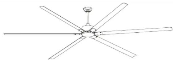
natural_image
Line drawing of a five-blade ceiling fan with a top-mounted head (no text or symbols)
INSTRUCTIONS PERTAINING TO RISK OF FIRE OR INJURY TO PERSONS READ ALL INSTRUCTIONS
IMPORTANT SAFETY INSTRUCTIONS
SAVE THESE INSTRUCTIONS
INSTALLATION AND WIRING TO BE IN ACCORDANCE WITH CEC,
NEC, LOCAL ELECTRICAL CODES and ANSI/NFPA 70.
Consult a qualified electrician if you are not familiar with wiring.
TOOLS AND MATERIALS REQUIRED
- Philips Screw Driver - Blade Screw Driver - Wire Cutters - Step Ladder
- Wiring supplies as required by electrical code.
NOTE: FOR OPTIMUM QUIETNESS, FULLY ASSEMBLE FAN AND RUN 24 HOURS
2157 Parkedale Ave..
Brockville, Ontario
K6V 5V6
PH: (613) 342-5424
FX: (613) 342-8437
2555 Rue Bernard
Lefebvre Laval, Quebec
H7C 0A5
PH: (450) 665-2535
FX: (450) 665-0910
SAFETY PRECAUTIONS
- Turn off power at main electrical service box before starting installation. 14
- Electrical connections must comply with local code ordinances, national electrical codes, CEC, NEC and ANSI/NFPA 70. ^13
- Make sure the installation site you choose allows the fan blades to rotate freely without any obstructions.
- When mounting the fan on a ceiling outlet box, Use an approved (CSA for Canada and UL for U.S.) ceiling fan box marked 'FOR FAN SUPPORT'. Ensure the outlet box is securely installed in place such that it is able to support at least the fan weight.
- WARNING: To reduce the risk of fire, electric shock, or other personal injury, mount fan only on an outlet box or supporting system marked acceptable for fan support of 35 lbs (15,9 kg) or less and use the mounting screws provided with the outlet box. Most outlet boxes commonly used for the support of lighting fixtures are not acceptable for fan support and may need to be replaced. Consult a qualified electrician if in doubt.
- Ensure that ONLY wet rated model for wet location.
- The fixing means for attachment to the ceiling such as hooks or other devices shall be fixed with a sufficient strength to withstand 4 times the weight of the ceiling fan.
- The mounting of the suspension system shall be performed by the manufacturer, its service agent or suitably qualified persons. ^8
- This ceiling fan is pre-built with luminaire. Do not use any other luminaire for this fan.
- This appliance is not intended for use by persons (including children) with reduced physical, sensory or mental capabilities, or lack of experience and knowledge, unless they have been given supervision or instruction concerning use of the appliance by a person responsible for their safety.
- Children should be supervised to ensure that they do not play with the appliance. 2
- Total Fan Weight For Reference: 120"approximate 15.0 kgs(33.08lbs), 96"approximate 13.5 kgs (29.77 lbs). 5
WARNING
- To reduce the risk of personal injury, DO NOT bend the blade brackets when installing the brackets, balancing the blades or cleaning the fan. Also, DO NOT insert foreign objects in between rotating fan blades. 10
- WARNING: TO REDUCE THE RISK OF FIRE, ELECTRIC SHOCK, OR PERSONAL INJURY, MOUNT TO OUTLET BOX MARKED ACCEPTABLE FOR FAN SUPPORT AND USE MOUNTING SCREWS PROVIDED WITH THE OUTLET BOX. 11
- Mount with the lowest moving parts at least 3.05 Meters (10 Feet) above floor or grade level.
- DO NOT operate reversing switch while fan blades are in motion. Fan must be turn off and rotating blades stopped completely, operate reverse switch and then operate speed switch for the opposite direction.
- Remove fan from the carton carefully and check for shipping damage. Check blades for bends and dents. In case assistance is required please contact our service centre.
- All set screws must be checked and re-tightened where necessary after installation. No lubricants should be used on screws or hooks.
- To reduce the risk of personal injury install the safety cable (per Fig.3b).
- DO NOT attach blades before hanging the fan.
- Used Batteries must be disposed of according to your local recycling regulations, many retail outlets provide special battery recycling drop off boxes.
- Do not mix battery types or voltages to avoid personal injury and/or damage to the fan and remote control.
- Direct wiring to an external variable speed wall control or dimmer switch of this fan and or external light kit will void warranty and make fan and light inoperable.
MAINTENANCE
- When properly maintained, fans can be expected to give years of trouble free operation.
- Properly maintained fans must be inspected every 3 months for vibration and wear on the support mechanism and that all screws, nuts, etc. are tight.
- To clean the fixture, turn off the power, wait for it to cool, and wipe the fixture with a clean, soft cloth.
- The replacement of parts of the safety suspension system device shall be performed by the manufacturer, its service agent or suitably qualified persons. 6
- WARNING: If unusual oscillating movement is observed, immediately stop using the ceiling fan and contact the manufacturer, its service agent or suitably qualified persons.
- Refer to (Fig. 11) for maintenance schedule
| DATE INSTALLED: | ||
| Visible Vibration Check Every 3 Months | Support Mechanism Refer to Installation Instructions (Every 3 Months) | Screws Refer to Installation Instructions (Every 3 Months) |
Fig.11
Supplier's Declaration of Conformity
47 CFR § 2.1077 Compliance Information
709 East Main Street, Teutopolis, Illinois, USA 62467
1.800.267.4427
This equipment has been tested and found to comply with the limits for a Class B digital device, pursuant to Part 15 of the FCC Rules. These limits are designed to provide reasonable protection against harmful interference in a residential installation. This equipment generates, uses and can radiate radio frequency energy and, if not installed and used in accordance with the instructions, may cause harmful interference to radio communications. However, there is no guarantee that interference will not occur in a particular installation. If this equipment does cause harmful interference to radio or television reception, which can be determined by turning the equipment off and on, the user is encouraged to try to correct the interference by one or more of the following measures:
- Reorient or relocate the receiving antenna.
– Increase the separation between the equipment and receiver. - Connect the equipment into an outlet on a circuit different from that to which the receiver is connected.
- Consult the dealer or an experienced radio/TV technician for help.
CAUTION:
Any changes or modifications not expressly approved by the grantee of this device could void the user's authority to operate the equipment. This device complies with Part 15 of the FCC Rules. Operation is subject to the following two conditions: (1) This device may not cause harmful interference, and (2) this device must accept any interference received, including interference that may cause undesired operation.
This device contains licence-exempt transmitter(s)/receiver(s) that comply with Innovation, Science and Economic Development Canada's licence-exempt RSS(s). Operation is subject to the following two conditions:
- This device may not cause interference.
- This device must accept any interference, including interference that may cause undesired operation of the device.

WARNING: Do NOT install this fan with variable speed wall control or wall-mounted dimmer switch. It will permanently damage the fan's remote control and cause the fan's function to fail.
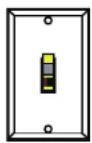
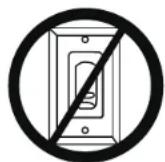
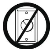
ON / OFF switch NO Variable
speed wall control
NO Dimmer switch
ASSEMBLY DRAWING
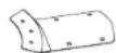
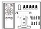
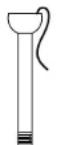
A. Canopy Cover
B. Mounting Bracket
C. Canopy
D. Downrod Assembly
E. Yoke Cover
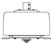
F. Fan Motor Assembly
G. Switch Housing
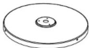
H. Switch Housing Cover
I. Blade Bracket
J. Remote Control
K. Fan Blade
A.

1.
B.

[Non-Text]
C.
D.

E.
K.
F.
H

Fig.1
Pg. #3
INSTALLATION
NOTE: All set screws must be checked and retightened where necessary, before and after installation.

PREPARING FOR MOUNTING
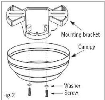
- Release the mounting bracket from the canopy by removing the two screws and washers.
text_image
Mounting bracket Canopy Washer Screw Fig.2
MOUNTING DOWNROD MOUNT
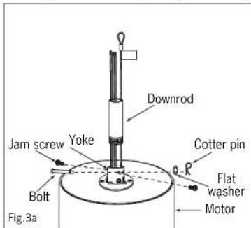
- Remove the hemisphere from downrod by loosening the hemisphere jam screw and lock pin.
- Remove Bolt, flat and cotter pin from the yoke. Slightly loosening the 2 jam screws on the yoke.
- Route the wires and safety cable through the downrod and screw the downrod into the yoke and align holes for the bolt to go through. Ensure not to damage the wires. Place the flat washer and cotter pin to lock the bolt. Re-tighten the 2 jam screws on the yoke
- Slide the yoke cover rubber ring and canopy into the downrod.
- Re-attach the hemisphere into the downrod. Insert the lock pin through the hole of downrod and put the lock pin in place on the hemisphere.
- Tighten the hemisphere jam screw against the downrod.
text_image
Downrod Jam screw Yoke Cotter pin Bolt Flat washer Motor Fig.3a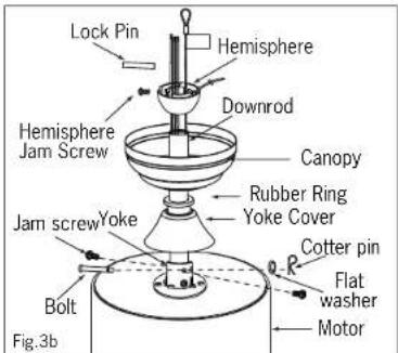
text_image
Lock Pin Hemisphere Downrod Canopy Rubber Ring Yoke Cover Jam screw Yoke Cotter pin Flat washer Motor Bolt Fig.3bPg. #4
TROUBLESHOOTING SUGGESTIONS
- Fan will not start
- Fan sounds noisy
-
Fan wobbles or shakes excessively.
-
Check wiring connections to fan.
- Check fuses and circuit breakers.
- Check wiring connections in switch housing.
CAUTION: Turn power off for last two items. - Check to make sure that all screws in motor housing are snug.
- Check to make sure that blade bracket screws are tight.
- Check to make sure that wire nuts in switch housing are not rattling against wall of switch housing.
- If fan has a light kit make sure switch housing screws and set screws are tight.
- Some fan motors are sensitive to signals from solid state variable controls. If solid state controller is used, change to an alternative control. (See a representative for a list of available controls.)
- Allow a 24 hour break in period to eliminate most noises.
- Check that all blades are screwed firmly into blade brackets.
- Check that blade brackets are secured firmly to motor.
- Check distance from tip of blades to ceiling.
- Check distance between blade tip to blade tip. All measurements should be equal. Loosen blade screws and position blade until even then re-tighten.
- Check that the downrod hemisphere notch is engaged in canopy
- Check to make sure that jam screws in downrod are tightened.
- Make sure canopy and mounting bracket are tightened securely to wooden joist.
- Make sure warpage has not occurred in wooden blades. If so, contact the customer service department for replacement parts.

INSTALLING THE SWITCH HOUSING COVER
WARNING: BE SURE TO TURN OFF POWER BEFORE INSTALLING
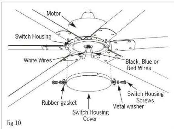
- Remove switch housing screws, metal washers and rubber gaskets on the switch housing cover.
- Align switch housing cover with switch housing and secure with three switch housing screws, metal washers and rubber gaskets.
text_image
Motor Switch Housing White Wires Black, Blue or Red Wires Rubber gasket Switch Housing Cover Metal washer Switch Housing Screws Fig.10WARNING: Ensure that all connections, set screws and screws are securely tightened before the next step.

INSTALL MOUNTING BRACKET
WARNING: To Reduce The Risk Of Fire, Electric Shock, Or Personal Injury, Mount To UL/CSA Listed Outlet Box Marked Acceptable for Fan Support And Use Mounting Screws Provided With The Outlet Box.
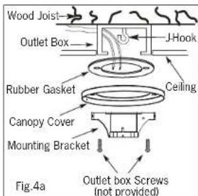
- Install J-Hook through center of outlet box and into the wooden joist.
- Secure mounting bracket, canopy cover and rubber gaskets to outlet box using outlet box screws
- Hang fan on mounting bracket and install safety cable.
- Hang the safety cable onto the J-hook.
- Carefully rotate fan assembly until groove in hemisphere locks over tab of canopy assembly.
- Insert bolt through metal washer, mounting bracket, hemisphere and metal washer, tighten with 2 hex nuts.
text_image
Wood Joist Outlet Box J-Hook Rubber Gasket Ceiling Canopy Cover Mounting Bracket Outlet box Screws (not provided) Fig.4a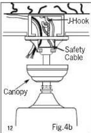
text_image
J-Hook Safety Cable Canopy 12 Fig. 4b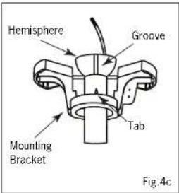
text_image
Hemisphere Groove Tab Mounting Bracket Fig.4c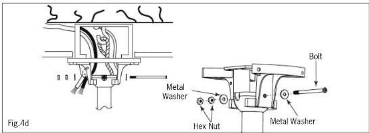
text_image
Fig.4d Metal Washer Bolt Hex Nut Metal Washer4
ELECTRICAL HOOK-UP
Direct wiring to an external variable speed wall control or dimmer switch of this fan and or external light kit will void warranty and make fan and light inoperable.
- There are several different wiring combinations that can be used in controlling your ceiling fan to meet your specific requirements. Should the following method not meet your requirements call or visit your nearest distributor for a full list of fan accessories.
CAUTION
| Green Wire - GROUND |
| Black Wire (Fan) - POWER |
| White Wire (Fan) - COMMON |
SEE SAFETY PRECAUTIONS ON PG. #2 BEFORE WIRING
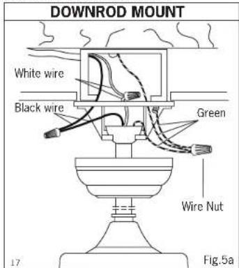
- Connect ground wire from outlet box to green wire from mounting bracket and downrod using a wire nut (not included).
- Connect white wire from outlet box to white wire from fan using wire nut (not included).
- Connect black wire from outlet box to black wire from fan using a wire nut (not included).
- After making the wire connections, ensure the wires should be spread apart with the grounded conductor and the equipment-grounding conductor on one side of the outlet box and the ungrounded conductor on the other side of the outlet box. 15
- Ensure the splices after being made should be turned upward and pushed carefully up into the outlet box. 16
text_image
DOWNROD MOUNT White wire Black wire Green Wire Nut Fig.5aNOTE: Once wires are connected, carefully tuck all wires and wire nuts into the metal outlet box making sure that the wires are clear of the hemisphere and downrod when positioned in mounting bracket (Downrod Mount Only).
Pg. #6 Pg. #9
7.
MOUNTING BLADES TO MOTOR
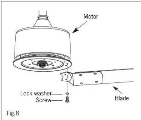
- Remove the screw and lock washer on the motor.
- Insert the blade arm into the fan as shown.
- Tighten the blade arm to the motor with the screw and lock washer removed in the previous step.
- Slightly turn the blade after installation and repeat the same step for the other blades.
text_image
Motor Lock washer Screw Blade Fig.88.
INSTALLING THE SWITCH HOUSING
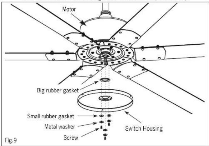
- Remove the screws, metal washers, and small rubber gaskets on the motor. - Attach the switch housing and big rubber gasket to the motor with the screws, metal washers and small rubber gaskets removed in the previous step.
text_image
Motor Big rubber gasket Small rubber gasket Metal washer Screw Switch Housing Fig.9
MOUNTING FAN ASSEMBLY
ENGAGE HEMISPHERE (Downrod Mount Only)
WARNING: Failure to seat tab in groove could cause damage to electrical wires and possible shock or fire hazard.
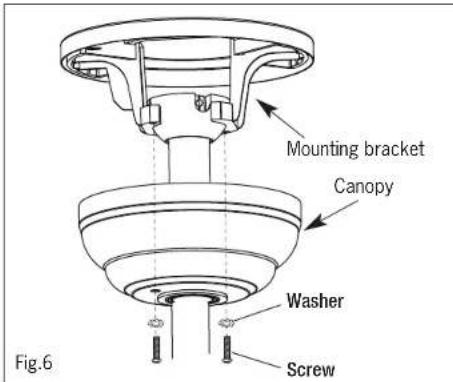
- Attach the canopy to mounting bracket using washers and screws.
text_image
Mounting bracket Canopy Washer Screw Fig.6NOTE: When installing fan on sloped ceiling, make sure tab on hanger bracket faces towards the top of the slope. Depending on the slope, a longer downrod may be required to prevent fan blades from hitting the ceiling.

MOUNT BLADE BRACKETS TO BLADES
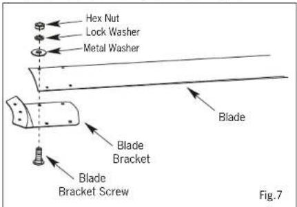
- Place blade bracket screw through blade bracket, blade, metal washer, lock washer and hex nut.
- Align with corresponding hole in blade bracket.
- Repeat with (2) remaining screws and tighten.
text_image
Hex Nut Lock Washer Metal Washer Blade Blade Bracket Blade Bracket Screw Fig.7Pg. #8 Pg. #7
4.
ELECTRICAL HOOK-UP
FUNCTION INSTRUCTION OF EMITTER
B
WARNING: Bypassing the remote and directly wiring fan or light voids warranty and will render the fan and light kit inoperable. Only use supplied remote control to operate the fan and light kit.
- Learning code and matching mode is used between transmitter and receiver.
- Turn "ON" the supply power. Within 30 seconds, press "FAN ON/OFF"
button on the transmitter for 5 seconds. Transmitter and receiver are connected after hearing a long "beep".
- If the transmitter cannot control the fan, check to ensure all wiring connections are properly connected according to the instruction manual. Check to ensure the batteries are in the right position. Check whether there are any similar remote controls in use nearby. Check whether they work with the same frequency.
- Low voltage of battery will affect the sensitivity of the transmitter. The indicator light will flash when battery voltage is low.
Replace the batteries for better performance.
- Take out the batteries from the transmitter when leaving unused for long periods of time.
- Ensure to connect the ground wire accordingly.
text_image
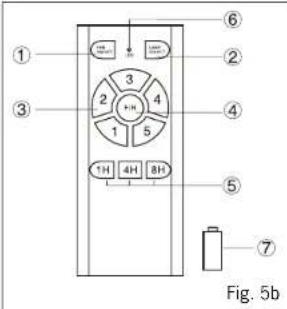
① ② ③ ④ ⑤ ⑥ ⑦ Fig. 5bREMOTE CONTROL
① ON/OFF the fan
② Short press: ON/OFF the light
Long press(hold for 3 seconds): Dimming
③ Speed of the fan (①low speed — ⑤high speed)
④ Direction of the fan (reverse switch)
⑤ Timing control of the fan
⑥ LED indicated light
⑦ 12V battery should be used in emitter

INSTALLING THE REMOTE CONTROL WALL BRACKET
If desired, the wall bracket can be installed to house the remote control.
- Use the screws to secure the wall bracket at the desired mounting location.
- Place the remote control into the wall bracket.
- Mount the cap onto the top of remote control as shown by the 2 screws if necessary.
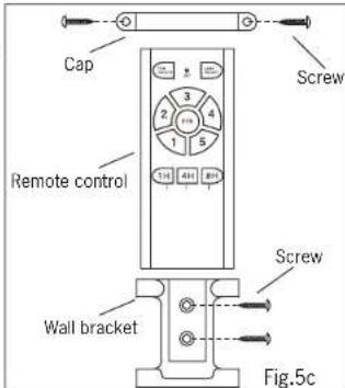
text_image
Cap Remote control Screw Wall bracket Fig.5cGARANTIE LIMITÉE DE 5 ANS
- Designed for high moisture and high humidity applications including Indoor and Outdoor applications porch, gazebo, barns, greenhouses and factories
- Meet's requirements of UL 507 - 10th Edition, CSA C22.2 No.60335-2-80:17, in conjunction with CSA C22.2 No.60335-1-16
- CSA/CSAus certified (file # 157644) for outdoor and agricultural use
- Passed UL rain test and corrosion test and CSA water spray test
- Sealed motor and housing
MODE D'INSTALLATION
SERIE MONTAGE AVEC TIGE
natural_image
Line drawing of a five-bladed ceiling fan with a top-mounted head (no text or symbols)
INSTRUCTIONS CONCERNANT LE RISQUE D'INCENDIES OU LES DOMMAGES DES PERSONNES LISEZ TOUTES LES INSTRUCTIONS
INSTRUCTIONS DE SURETE IMPORTANTES
GARDEZ CES INSTRUCTIONS
2157 Parkedale Ave.,
Brockville, Ontario
K6V 5V6
PH: (613) 342-5424
FX: (613) 342-8437
2555 Rue Bernard
Lefebvre Laval, Quebec
H7C 0A5
PH: (450) 665-2535
FX: (450) 665-0910
MISE EN GARDE
DATE D'INSTALLATION:
Supplier's Declaration of Conformity
47 CFR § 2.1077 Compliance Information
709 East Main Street, Teutopolis, Illinois, USA 62467
1.800.267.4427