
KE-14S - Industrial fan Canarm - Free user manual and instructions
Find the device manual for free KE-14S Canarm in PDF.


| Brand | Canarm |
| Model | KE-14S |
| Product Type | Industrial radial blade fan, direct drive |
| Wheel (diameter x width) | 13-1/2 x 8-1/8 inches |
| Wheel Bore | 7/8 inch |
| Dimensions (A x B x C x D x E x F x G x H x J x K x L x M x N x O x P x R x V x X) | See table: A=17-5/8, B=10-1/2, C=14-5/8, D=10-3/4, E=8, F=8-3/4, G=7/8, H=11-1/8, J=9-3/8, K=12-5/8, L=11-3/8, M=16-3/4, N=9/16, O=7, P=14-1/2, R=14-5/8, V=12-1/4, X=17 inches |
| Mounting Holes | 4 holes of diameter 9/16 inch |
| Power Supply | Three-phase, voltage and current per motor nameplate |
| Frequency | 50/60 Hz (depending on motor) |
| Motor Speed | Per nameplate (e.g., 1750 rpm typical) |
| Main Functions | Industrial ventilation, air extraction or blowing |
| Materials | Steel, with sheet metal wheel |
| Installation | On a solid foundation, fasten with bolts in the designated holes |
| Safety | Lock out power before intervention, mandatory grounding, protection for non-ducted openings |
| Maintenance | At least annual inspection, check fastenings and clean wheel |
| Troubleshooting | Scraping noise: align wheel/venturi; vibrations: clean or tighten; reduced flow: rotation direction or debris |
| Warranty | 1 year against defects in materials and workmanship (parts only) |
| After-sales service | Contact Canarm Ltd. |
Frequently Asked Questions - KE-14S Canarm
User questions about KE-14S Canarm
0 question about this device. Answer the ones you know or ask your own.
Ask a new question about this device
Download the instructions for your Industrial fan in PDF format for free! Find your manual KE-14S - Canarm and take your electronic device back in hand. On this page are published all the documents necessary for the use of your device. KE-14S by Canarm.
USER MANUAL KE-14S Canarm
PLEASE READ AND SAVE THESE INSTRUCTIONS

CANARM®
HVAC
The purpose of this manual is to aid in the proper installation and operation of the Canarm KE Series direct drive radial blade blowers. These instructions are intended to supplement good general practices and are not intended to overwrite local codes and ordinances.
IT IS THE RESPONSIBILITY OF THE PURCHASER TO ENSURE THAT THE INSTALLATION AND MAINTENANCE OF THIS EQUIPMENT IS HANDLED BY QUALIFIED PERSONNEL.
Inspect all shipments carefully for damage. THE RECEIVER MUST NOTE ANY DAMAGE ON THE CARRIER'S BILL OF LADING AND FILE A CLAIM IMMEDIATELY WITH THE FREIGHT COMPANY.
GENERAL SAFETY
The KE series come prepared from the factory, ready to run when installed and wired. 1.
- All electrical work must be done in accordance with all applicable electrical codes by a qualified electrician.
- Prior to wiring the unit, ensure the power supply is locked out in the OFF position and that the voltage matches the motor's requirement, located on the motor's name plate.
- Caution: The unit contains rotating parts, & electrical service. Use appropriate caution when installing and servicing the unit. Install guarding around the intake venturi, or outlet discharge in applications where it will be not be ducted.
Before starting the unit, ensure all parts are secure & the wheel rotates freely. 5.
- Check and tighten where necessary all screws, nuts, bolts, etc. prior to starting the unit. Some may have loosened during shipping.
- NOTE: Check and tighten all hardware after 2 days of initial operation. Make sure there is no foreign debris in the fan compartment or lodged in the wheel itself. 8.
- Blowers should be installed on solid structural foundations. Vibration isolators are recommended. Work should be done under the supervision of licensed mechanical contractors
Always wear appropriate safety equipment when installing or 10. servicing the unit.
Please follow all applicable national, state/provincial and 11. local codes. All of them will supersede this manual.
Failure to follow the safety instructions in this manual may 12. cause serious injury or death due to electrical shock or high speed rotating parts.
natural_image
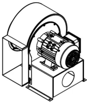
Technical line drawing of an electric motor inside a rectangular housing (no text or symbols)DIMENSIONS & COMPONENTS
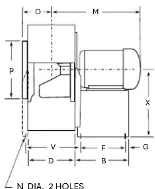
(Only on Model KE-12 KE-14)

| MODEL NO. | WHEEL | BORE | A | B | C | D | E | F | G | H | J | K | L | M* | N | O | P | R | V | X |
| KE-8 | 7-3/4 x 4 | 1/2 | 11 | 8 | 8-1/4 | 5-3/8 | 5 | 7 | 1/2 | 6 | 4-5/8 | 6-3/4 | 6-7/8 | 10-3/4 | 3/8 | 3-3/4 | 8 | 8 | --- | 8-1/2 |
| KE-9 | 9 x 5 | 1/2 | 12-1/8 | 8 | 10-3/4 | 6-1/2 | 5-5/8 | 7 | 1/2 | 6-3/4 | 5-5/8 | 7-3/4 | 7-1/8 | 11-3/4 | 3/8 | 4-5/16 | 9 | 9-1/4 | --- | 9-3/8 |
| KE-11 | 10-7/8 x 5-5/8 | 5/8 | 14-3/4 | 9 | 11-3/4 | 8 | 6-7/8 | 7-1/2 | 3/4 | 8 | 6-3/4 | 9-1/8 | 8-1/8 | 13-1/4 | 3/8 | 5-1/16 | 10 | 10-3/4 | --- | 11-3/4 |
| KE-12 | 12-1/2 x 7-1/2 | 7/8 | 16-3/8 | 10-1/2 | 13-1/4 | 9-5/8 | 7-3/8 | 8-3/4 | 7/8 | 10-1/8 | 8-1/2 | 11-1/2 | 10-1/2 | 15-3/16 | 9/16 | 6-3/8 | 13-1/4 | 13-1/4 | 11-1/8 | 17 |
| KE-14 | 13-1/2 x 8-1/8 | 7/8 | 17-5/8 | 10-1/2 | 14-5/8 | 10-3/4 | 8 | 8-3/4 | 7/8 | 11-1/8 | 9-3/8 | 12-5/8 | 11-3/8 | 16-3/4 | 9/16 | 7 | 14-1/2 | 14-5/8 | 12-1/4 | 17 |
INSTALLATION
- Carefully remove the KE and any associated parts from its crate. The skid can be used to help lift it to its installation site.
- Inspect the unit and make sure the fan wheel rotates freely. Inspect all hardware and fasteners, some may have loosened during shipping. Make sure the unit is free of all foreign debris. Use caution when lifting the unit, some models may be very heavy.
- The blower should be installed on a properly designed foundation. It can be secured using the multiple 3/8" - 9/16" diameter holes provided.
- If you need to modify the unit for any reason to install it, do so under the supervision of a licensed mechanical contractor or contact Canarm before making any alterations.
- Once secured, complete all required duct connections. Any un-ducted orifice should be guarded to avoid contact with rotating parts.
- Make sure the motor compartment is free and clear and can be accessed in case of service. Rotate the wheel, it should spin freely and not make any sound that would indicate the wheel is rubbing against any debris or the venturi itself.
- All wiring must be completed by qualified personnel only and done in accordance with local codes. Refer to the motor's name plate for details. Ensure branch power supply matches the motor requirement. Phases, voltages and amperage available on the circuit.
- Caution: Always ensure the power is locked out in the off position prior to performing any electrical work. When complete, have qualified personnel inspect the unit prior to energizing. 9.
- Briefly energize the unit and ensure the wheel rotation matches the sticker indicating proper rotation direction. If it does not, check your electrical connections. Check that the amperage drawn matches the motor's FLA as indicated.
- If you notice any irregular vibration, shut the unit off, lock out power supply, and inspect it. Listen for any irregular sounds. Refer to the trouble shooting section of this manual, or contact Canarm if you need assistance.
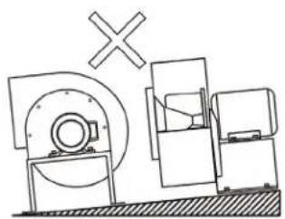
FIG. 1: PREPARE FOUNDATION
natural_image
Technical line drawing of a mechanical assembly with no visible text or symbols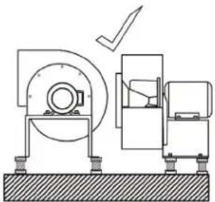
natural_image
Technical line drawing of a mechanical device with a checkmark indicating operation (no text or symbols present)A solid foundation should be prepared for the blower. It should be level, and approved by building code for the application.
Use the provided 3/8 – 9/16 diameter holes to secure the fan. Isolators may be used, but are not required.
LOCATE AND FOLLOW THE MOTOR'S NAME PLATE FOR ELECTRICAL DETAILS ENSURE BRANCH POWER SUITS THE MOTORS NEEDS.
FIG. 2: REFER TO MOTOR NAMEPLATE
| AC MOTOR IEC EFF1 | |||||
| TYP | SER. NO. | YR. | |||
| KW | RPM | V | A | HZ | |
| KW | RPM | V | A | HZ | |
| DUTY | INSUL | AMB | C | RISE K | 3 PHASE |
| COS | CODE | IP | IC | SRV, FAC. | |
| GREASE | BRG | BRG | WEIGHT | ||
| CE | |||||
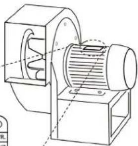
natural_image
Technical line drawing of a mechanical device with internal components and no visible text or symbolsFIG. 3: GUARDING OPENINGS
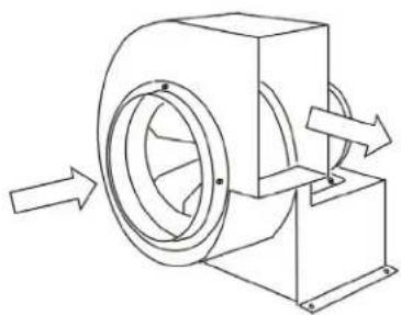
natural_image
Technical line drawing of a mechanical device with directional arrows indicating motion (no text or symbols)In cases where the intake or outlet of the fan are NOT ducted, ensure to install guarding adequate to prevent accidental contact with high speed rotating parts.
Inside the venturi and wheel, you will find a set screw binding the wheel to the motor shaft. Loosen it.
FIG. 4: WHEEL & VENTURI ALIGNMENT
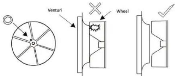
NOTE:
When loosening and removing the wheel, it should be set with clearance so it spins freely without scraping the housing. Loosen the bolts around the venturi to help align them.
ELECTRICAL

WARNING
A GROUND WIRE MUST BE CONNECTED FROM THE UNIT CHASSIS TO A SUITABLE ELECTRICAL GROUND.

WARNING
ENSURE POWER SUPPLY IS DISCONNECTED AND LOCKED OUT PRIOR TO MAKING ELECTRICAL CONNECTIONS.
Before connecting the motor to the electrical supply, check the electrical characteristics and wiring instructions as indicated on the motor nameplate or as shown below. Complete electrical connection as indicated

WARNING
A GROUND WIRE MUST BE CONNECTED FROM THE MOTOR HOUSING TO A SUITABLE ELECTRICAL GROUND.
PRE-START INSPECTION
Set the main power breaker switch to "OFF" & lockout the power supply. 1.
- Check all fasteners on the unit and those that may mount the unit to its foundation. Some may have vibrated loose during shipping or handling during set up.
- Rotate the wheel to ensure that it rotates freely and nothing comes in contact with the housing. If it does see Fig. 4.
- Verify branch power, and that your motor is wired and suitable for its supply. Failure to do so may cause damage or lead to premature motor failure (Fig. 2).
Check to ensure that all guards and accessories are securely mounted (Fig 3). 5.
- Once the unit's hardware and power supply are verified, you may proceed to test the unit. Remove any power lockouts and proceed with unit activation.
START UP
Turn the fan on and inspect for the following immediately:
- Any unusual sound or vibration.
- Direction of wheel rotation
- Improper motor amperage
If a problem is encountered, shut off the fan and refer to the section on troubleshooting to discover the cause of the problem. The fan should then be inspected after 30 minutes, 8 hours & 24 hours of operation to ensure all fasteners are tight and the unit is operating correctly.
MAINTENANCE
- All maintenance and wiring should be completed by qualified personnel in accordance with National & Local Codes.
- It is recommended to establish a regular maintenance procedure that works within your organization. The ventilator should be inspected at least once a year. More regular inspections are recommended in critical applications.
- The unit should be shut off and its electrical supply locked out prior to engaging in any maintenance activities.
- It is recommended to inspect all fasteners periodically. Vibration over time may loosen them.
- If any new or unknown symptoms are found, refer to the troubleshooting section of this manual or contact Canarm.
- NOTE: The fan should operate within its design and duty point in the HVAC system. Use outside of its specification could cause damage to the fan, or the larger system its connected to.
- Check static pressure and any accessories like dampers. Check the amperage draw of the motor. These things can be early indicators of issues within the fan or system its connected to.
FAN TROUBLESHOOTING

WARNING
MAKE SURE THE UNIT IS NOT CAPABLE OF OPERATION DURING INSPECTION & REPAIR.

WARNING
THE UNIT CONTAINS HIGH SPEED ROTATING PARTS AND ELECTRICAL SERVICE.

WARNING
A GROUND WIRE MUST BE CONNECTED FROM THE MOTOR HOUSING TO A SUITABLE ELECTRICAL GROUND.

WARNING
A GROUND WIRE MUST BE CONNECTED FROM THE UNIT CHASSIS TO A SUITABLE ELECTRICAL GROUND.
| PROBLEM POSSIBLE ISSUE SOLUTION | ||
| Scraping sound | Wheel rubbing the inlet | Inspect wheel alignment to the inlet, it may have shifted during shipping. Loosen bolts fixing inlet to the housing and adjust until the wheel moves freely. |
| Wheel slipped on motor shaft | Inspect bushing connecting motor shaft to the wheel. Tighten set screws if necessary. | |
| Reduced airflow | Wrong wheel rotation Check and reverse shaft rotation direction of the motor. | |
| Debris in unit Clean out wheel and housing with pressurized air. | ||
| Debris in ductwork Inspect the duct system for obstructions. | ||
| Unit does not run | Power supply issue | Ensure proper power supply for the motor, breakers and fusing. |
| Motor needs replacement Check m motor wiring and other potential causes. | ||
| Excessive vibration | Wheel out of balance Clean and buildup of dust, dirt or debris on the wheel. | |
| Loose hardware Check all hardware that may have loosened. | ||
Please contact Canarm Ltd. for any maintenance related questions. One of our technicians will be able to help you with specific questions.
WARRANTY
CANARM Ltd. warrants every new fan to be free of defects in material and workmanship to the extent that, within a period of one year from the date of purchase CANARM Ltd. shall either repair or replace at CANARM's option, any unit or part thereof, returned freight prepaid and found to be defective.
This warranty does not include any labour or transportation costs incidental to the removal and reinstallation of the unit at the user's premises.
NOTICE: No warranty claims will be honored by CANARM Ltd. unless prior authorization is obtained.
KE SERIES
VENTILATEUR À PALES RADIALES À ENTRAÎNEMENT DIRECT
MODE D'OPÉRATION
LIRE ET CONSERVER CES INSTRUCTIONS

CANARM®
HVAC
natural_image
Technical line drawing of an electric motor inside a box (no text or symbols)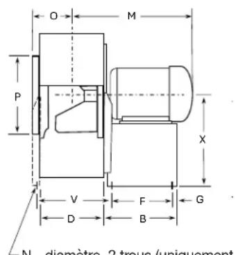
natural_image
Technical line drawing of a mechanical assembly with no visible text or symbols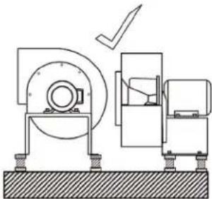
natural_image
Technical diagram of a mechanical assembly with no visible text or symbolsnatural_image
Technical line drawing of a mechanical device with internal components and mounting base (no text or symbols)natural_image
Technical line drawing of a mechanical device with directional arrows indicating motion (no text or symbols)Brand : Canarm
Model : KE-14S
Category : Industrial fan