
APL20-AE2003 - Industrial fan Canarm - Free user manual and instructions
Find the device manual for free APL20-AE2003 Canarm in PDF.


| Product type | Industrial plenum fan (APL) |
| Brand | Canarm |
| Model | APL20-AE2003 |
| Use | Indoor industrial, well-ventilated |
| Motor | EC Infinitum Aircore permanent magnet motor with integrated VFD |
| Speed | Variable via built-in variable frequency drive |
| Power supply | Check nameplate for required voltage and current |
| Installation | Structural mounting via 4 holes of 9/16 in; provide access to motor for maintenance |
| Maintenance | Quarterly inspection (3 months or 500 hours); clean debris, check fasteners |
| Electrical safety | Lock out power before intervention; wait 1 min for capacitor discharge |
| Mechanical safety | Rotating parts; wear protective equipment; prevent rotation during installation (current generated even when disconnected) |
| Warranty | 1 year against defects in material and workmanship |
| Compliance | Comply with national, state/provincial, and local codes |
| Weight | Not specified in manual (plan for appropriate lifting equipment) |
| Dimensions | Not specified |
| Noise | Check for absence of scraping noise; wheel may rub inlet after transport |
Frequently Asked Questions - APL20-AE2003 Canarm
User questions about APL20-AE2003 Canarm
0 question about this device. Answer the ones you know or ask your own.
Ask a new question about this device
Download the instructions for your Industrial fan in PDF format for free! Find your manual APL20-AE2003 - Canarm and take your electronic device back in hand. On this page are published all the documents necessary for the use of your device. APL20-AE2003 by Canarm.
USER MANUAL APL20-AE2003 Canarm
READ AND SAVE THESE INSTRUCTIONS
The purpose of this manual is to aid in the proper installation and operation of the Canarm array Plenum Fan (APL). These instructions are intended to supplement good general practices and are not intended to overwrite local codes and ordinances.
IT IS THE RESPONSIBILITY OF THE PURCHASER TO ASSURE THAT THE INSTALLATION AND MAINTENANCE OF THIS EQUIPMENT IS HANDLED BY QUALIFIED PERSONNEL.
Inspect all shipments carefully for damage. THE RECEIVER MUST NOTE ANY DAMAGE ON THE CARRIER'S BILL OF LADING AND FILE A CLAIM IMMEDIATELY WITH THE FREIGHT COMPANY.
GENERAL SAFETY
- The APL EC series unit(s) comes with an onboard VFD.
- All electrical work must be done in accordance with all applicable electrical codes by a qualified electrician.
- Prior to wiring the unit, ensure power supply is locked out in the OFF position, and voltage matches the motor's requirement.
- Do not install or operate this fan in an environment where combustible materials, gases, fumes. It is intended for well ventilated indoor industrial use only.
- The motor should be easily accessed for cleaning and maintenance, do not obstruct its air cooling inlets and outlets.
- Caution: the unit contains rotating parts and electrical components. Use appropriate caution when installing and servicing it.
- Before starting the unit, ensure all parts are secure & the wheel rotates freely.
- Check and tighten where necessary all nuts, bolts & set screws prior to unit start up (as some may have loosened during shipment).
- NOTE: Check and tighten all hardware after 2 days of initial operation.
- Make sure there is no foreign debris in the fan compartment or lodged in the wheel itself.
- It is the customers' responsibility to ensure the installation location is prepared and adequate under local building codes to bear the weight of the mounted fan.
- Inspect electrical components prior to completing electrical connections. Make sure everything is tight and free of damage that may have occurred in shipping.
- Always wear appropriate safety equipment when installing or servicing the unit.
- Please follow all applicable national, state/provincial and local codes, all of them will supersede this manual.
- Failure to follow the safety instructions in this manual may cause serious injury or death due to electrical shock or high speed rotating parts.
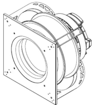
natural_image
Technical line drawing of a mechanical assembly with mounting flanges and housing (no text or symbols)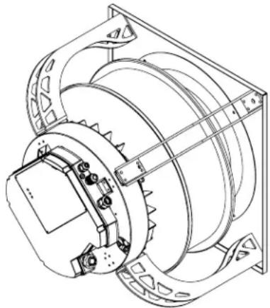
natural_image
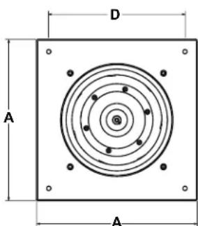
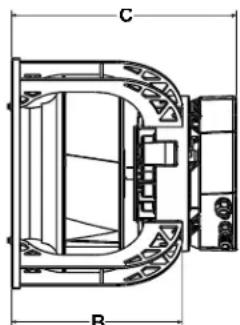
Technical line drawing of a mechanical device with gears and mounting brackets (no text or symbols)DIMENSION & COMPONENT
| MODEL | A | B | C (CHANGES BASED ON MOTOR SIZE) | MOUNTING | |||
| INFINITUM 130 | INFINITUM 150 | INFINITUM 180 | INFINITUM 205 | ||||
| APL12-DP-EC | 15 1/4"12 | 3/8"17 3/8"---11 1/4" | |||||
| APL14-DP-EC | 17" | 13 3/8" | 18 3/8" | 18" | - | - | 12 13/16" |
| APL16-DP-EC | 19" | 14 3/8" | 19 3/8" | 19" | 19 1/8" | - | 14 13/16" |
| APL18-DP-EC | 21" | 15 5/8" | 20 5/8" | 20 1/4" | 20 3/8" | 20 1/4" | 16 13/16" |
| APL20-DP-EC | 23 1/4" | 16 3/4" | 21 3/4" | 21 3/8" | 21 1/2" | 21 3/8" | 19 1/16" |
| APL22-DP-EC | 26" | 18 1/4" | 23 1/4" | 22 7/8" | 23" | 22 7/8" | 21 13/16" |
| APL25-DP-EC | 29 1/4" | 19 7/8" | 24 7/8" | 24 1/2" | 24 5/8" | 24 1/2" | 28 9/16" |
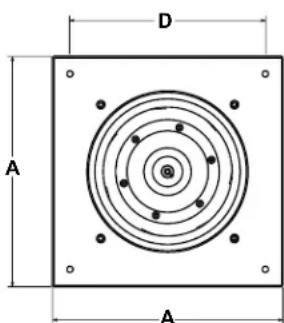
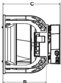
natural_image
Technical line drawing of a mechanical assembly with labeled dimensions C and B (no text or symbols present)INSTALLATION
- Carefully remove the APL and any associated parts from its crate, use only approved lifting methods, units will be heavy.
- Inspect the unit, make sure the fan wheel rotates freely. Inspect all hardware and fasteners, some may have loosened in shipping. Make sure the unit is free of all foreign debris.
- Units will be prepared with mounting locations through the venturi plate, and structural motor mount arms, use these to fasten the unit in its installation position. Figure 1.
-
If you need to modify the unit for any reason to install it, do so under the supervision of a licensed mechanical contractor, or contact Canarm before making any alterations.
-
Once the fan is secured, complete any ducting required in your system.
- Make sure the motor, and its electrical compartment are free and clear and can be accessed in case of service.
- When secure, remove the cover of the motor's electrical compartment. All Wiring must be completed by qualified personnel only and done in accordance with local codes.
-
Infinitum Aircore EC motor's come equipped for variable speeds with an on board VFD.
-
Please review the Infinitum Installation, Operation and Maintenance manual linked on page 3 of this document.
-
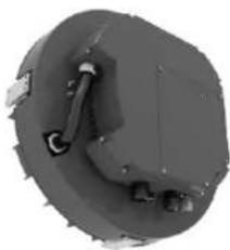
Caution: Ensure all wiring or conduit is secured and cleanly restrained away from any rotating parts. Figure 2.
-
Caution: Always ensure branch power is locked out in the off position prior to performing any electrical work. Ensure power supply matches the requirement of the motor, this will be labeled on the product.
-
When complete, Inspect the unit with qualified personnel prior to energizing the unit.
-
Once electrical connections are complete and inspected, replace the motor's electrical compartment cover using the supplied hardware.
FIGURE 1: SIMPLE INSTALLATION DIAGRAM
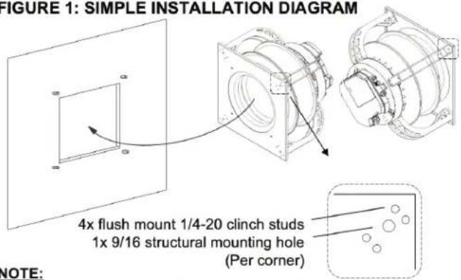
NOTE: Structural mounting provisions to be supplied by others. Canarm's APL will feature 4 x 9/16" holes where a lag bolt or similar can be used to fix the unit in its installation position.
FIGURE 2: ACCESS AND VENTING
When planning your installation, make sure to provide full access to the motor.
This will be important for regular maintenance cycles. Which should be scheduled every quarter or 3 months.
DO NOT block the motor's venting ports. They are critical for the motor's long-term function.
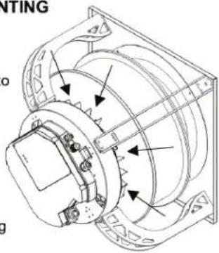
FIGURE 3: WHEEL RESTRAINT
It is also advised that you restrain the wheel from spinning during installation.
The motor uses a permanent magnet Architecture, so when the wheel is spun, the motor will generate current even when disconnected.
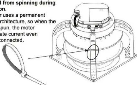
A proper rated zip tie or similar may be applied through the frame to bind one of the wheel's blades.
FIGURE 4: ELECTRICAL WIRE MANAGEMENT
When wiring the motor for power and/or controls, ensure to restrain cabling to the frame of the fan in such a way it cannot possibly come in contact with the wheel's rotation.
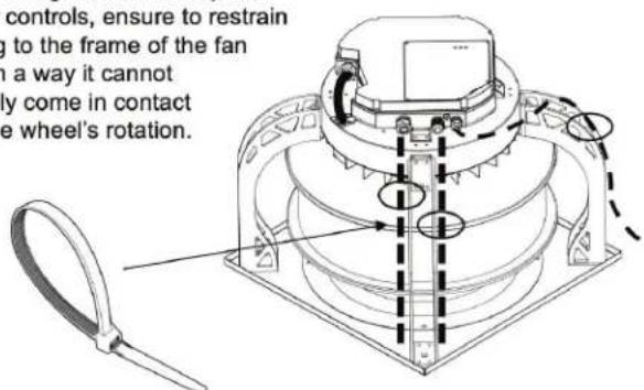
A proper rated zip tie or similar may be applied to facilitate this.
STANDARD WIRING DIAGRAMS
- All wiring should be completed by a qualified electrician in accordance with National & Local Electrical Codes.
- Ensure power supply is disconnected & the unit is locked out prior to performing any electrical work.
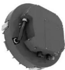
- The unit's motor has a large electrical compartment on the back of the motor.
- Refer to the Infinitum technical document linked below in this manual for specific wiring details. Figure 5.
- Excess wire as a result of service to the unit must be restrained cleanly, safely and kept away from rotating parts.
- If excess wire needs to be cut, ensure you label all wire extensions prior to cutting.
- Disconnect switches in close proximity to the unit are recommended in case the need arises to swiftly disconnect power.
- Consult the Infinitum manual for specific motor requirements.
FIGURE 5 - INFINITUM INSTALLATION, OPERATION & MAINTENANCE MANUAL
Infinitum

Aircore EC
Installation, Operation & Maintenance Manual
natural_image
Close-up of a mechanical component with textured surfaces and a central protrusion (no visible text or symbols)Infinitum
Aircore EC
Installation, Operation & Maintenance Manual
natural_image
Workers installing equipment in a large industrial facility (no visible text or symbols)SCAN QR CODE OR VISIT LINK BELOW TO VIEW/DOWNLOAD INFINITUM MANUAL https://support.goinfinitum.com/hc/en-us/articles/28039799952915-Aircore-EC-Installation-Operation-Maintenance-Manual
PRE-START INSPECTION
- Set the main power breaker switch to "OFF" & lockout the power supply.
- Check all fasteners on the unit and those that mount the unit to the installation structure. Some may have vibrated loose during shipping or handling during set up.
- Rotate the wheel to ensure that it rotates freely and nothing comes in contact with the housing. Note, this will generate current being a Permanent Magnet motor.
- Verify branch power, that your motor is wired and suitable for its supply. Failure may damage, or cause the motor to fail prematurely.
- Check to ensure that all guards and accessories are securely mounted. If you guard the fan, ensure motor access remains and you do not block the ventilation ports.
- Once the unit's hardware, and power supply are verified. You may proceed and test the unit. Remove power lockouts and proceed with unit activation to ensure rotation direction is correctly set.
START UP
Turn the fan on and inspect for the following:
- Any unusual sound or vibration.
- Direction of wheel rotation
- Improper motor amperage
If a problem is encountered, shut off the fan and refer to the section on troubleshooting, or the Infinitum manual linked above to discover the cause of the problem. The fan should be inspected after 30 minutes, 8 hours & 24 hours of operation to ensure all fasteners are tight and the unit is operating correctly.
MAINTENANCE
- All maintenance and wiring should be completed by a qualified personnel in accordance with National & Local Codes.
- Ensure power supply is disconnected & the unit is locked out prior to performing any work on the APL.
- Allow 1 minute minimum for motor capacitors to discharge.
- The ventilator should be inspected at least once a quarter, three months, or 500 working hours (whichever comes first), more regular inspections are recommended in critical applications.
- It is also recommended to inspect all fasteners periodically, vibration over time may loosen them.
- Make sure to clear any debris that may have gathered in the motor's cooling ports.
- Inspect any internal wires for signs of heat damage.
FAN TROUBLESHOOTING

WARNING
MAKE SURE THE UNIT IS NOT CAPABLE OF OPERATION OR ROTATION DURING INSPECTION AND REPAIR.

WARNING
THE UNIT CONTAINS HIGH SPEED ROTATING PARTS AND ELECTRICAL COMPONENTS.

WARNING
A GROUND WIRE MUST BE CONNECTED FROM THE MOTOR HOUSING TO A SUITABLE ELECTRICAL GROUND.

WARNING
A GROUND WIRE MUST BE CONNECTED FROM THE UNIT CHASSIS TO A SUITABLE ELECTRICAL GROUND
| PROBLEM POSSIBLE ISSUE SOLUTION | ||
| Scraping sound | Wheel rubbing the inlet | Inspect wheel's alignment to the inlet. It may have shifted in shipping.Loosen bolts fixing inlet to the housing and adjust until the wheel moves freely. |
| Wheel slipped on motor shaft Loose bushing connecting motor shaft to the wheel. Tighten set screws. | ||
| Reduced airflow | Wrong wheel rotation Check and reverse shaft rotation direction of the motor. | |
| Debris in unit Clean out wheel & housing with pressurized air. | ||
| Debris in ductwork Inspect the duct system for obstructions. | ||
| Unit doesn't run | Power supply issue Ensure proper power supply for the motor, breakers, fusing. | |
| Motor needs replacement Check motor's wiring and other potential causes. | ||
| Excessive vibration | Wheel out of balance Check for build up of dust, dirt or debris on the wheel. | |
| Loose hardware Check all hardware that may have loosened over time from vibration. | ||
Contact Canarm Ltd. for any and all maintenance related questions. One of our helpful technicians will be able to help you with specific questions.
You can also find full contact information for Infinitum at the end of their manual, which you can view/download by following the link on page 3 of this document.
WARRANTY
CANARM Ltd. warrants every new fan to be free of defects in material and workmanship to the extent that, within a period of one year from the date of purchase CANARM Ltd. shall either repair or replace at CANARM's option, any unit or part thereof, returned freight prepaid and found to be defective.
This warranty does not include any labour or transportation costs incidental to the removal and reinstallation of the unit at the user's premises.
NOTICE: No warranty claims will be honored by CANARM Ltd. unless prior authorization is obtained.
SÉRIE APL-DP-EC RÉSEAU À ENTRAÎNEMENT DIRECT CANARM VENTILATEUR PLÉNUM – INFINITUM AIRCORE
MODE D'OPÉRATION LIRE ET GARDER CES INSTRUCTIONS

CANARM®
HVAC
natural_image
Technical line drawing of a mechanical assembly with mounting flanges and housing (no text or symbols)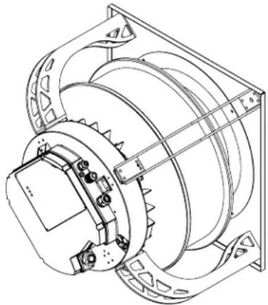
natural_image
Technical line drawing of a mechanical device with gears and mounting brackets (no text or symbols)DIMENSIONS ET COMPOSANTS
| MODÈLE | A | B | C (CHANGEMENTS BASÉS SUR LA TAILLE DU MOTEUR) | MONTAGE | |||
| INFINITUM 130 | INFINITUM 150 | INFINITUM 180 | INFINITUM 205 | ||||
| APL12-DP-EC1 | 5 1/4"12 | 3/8"17 3/8" | --11 1/4" | ||||
| APL14-DP-EC1 | 7"13 3/8" | 18 3/8"18" | --12 13/16" | ||||
| APL16-DP-EC1 | 9"14 3/8" | 19 3/8"19" | 19 1/8"-14 13/16" | ||||
| APL18-DP-EC | 21" | 15 5/8" | 20 5/8" | 20 1/4" | 20 3/8" | 20 1/4" | 16 13/16" |
| APL20-DP-EC | 23 1/4" | 16 3/4" | 21 3/4" | 21 3/8" | 21 1/2" | 21 3/8" | 19 1/16" |
| APL22-DP-EC | 26" | 18 1/4" | 23 1/4" | 22 7/8" | 23" | 22 7/8" | 21 13/16" |
| APL25-DP-EC | 29 1/4" | 19 7/8" | 24 7/8" | 24 1/2" | 24 5/8" | 24 1/2" | 28 9/16" |
natural_image
Technical line drawing of a mechanical assembly with labeled dimensions C and B (no text or symbols present)INSTALLATION
natural_image
Technical line drawing of a mechanical device with rotating components and mounting brackets (no text or symbols)Installation, Operation & Maintenance Manual
natural_image
3D rendered mechanical component with no visible text or symbols
Infinitum
Aircore EC
Installation, Operation & Maintenance Manual
natural_image
Workers installing equipment in a multi-level industrial facility (no visible text or symbols)SCANNER LE CODE QR OU CLIQUER SUR LE LIEN CI-DESSOUS POUR
CONSULTER/TÉLÉCHARGER LE MANUEL INFINITUM
https://support.goinfinitum.com/hc/en-us/articles/28039799952915-Aircore-EC-Installation-Operation-Maintenance-Manual
INSPECTION AVANT DÉMARRAGE
Brand : Canarm
Model : APL20-AE2003
Category : Industrial fan