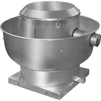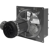
SD12-XPF - Fan Canarm - Free user manual and instructions
Find the device manual for free SD12-XPF Canarm in PDF.


User questions about SD12-XPF Canarm
0 question about this device. Answer the ones you know or ask your own.
Ask a new question about this device
Download the instructions for your Fan in PDF format for free! Find your manual SD12-XPF - Canarm and take your electronic device back in hand. On this page are published all the documents necessary for the use of your device. SD12-XPF by Canarm.
USER MANUAL SD12-XPF Canarm
STANDARD EXHAUST FANS
CANARM®
OPERATION INSTRUCTIONS AND PARTS MANUAL READ AND SAVE THESE INSTRUCTIONS
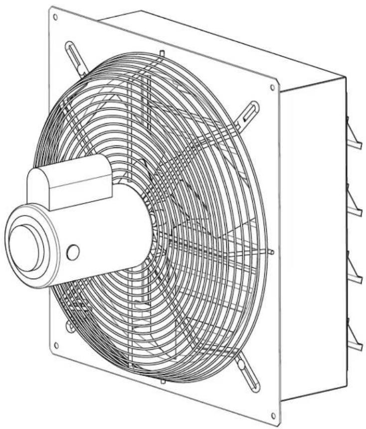
natural_image
Technical line drawing of a mechanical fan or vent with internal mesh structure (no text or symbols)WARRANTY
CANARM Ltd. warrants every new fan to be free of defects in material and workmanship, to the extent that, within a period of one year from the date of purchase CANARM Ltd. shall either repair or replace at CANARM's option, any unit or part thereof, returned freight prepaid, and found to be defective.
This warranty does not include any labour or transportation costs incidental to the removal and reinstallation of the unit at the user's premises. Components repaired or replaced are warranted through the remainder of the original warranty period only.
This warranty applies to the original purchaser-user only; it is null and void in case of alteration, accident, abuse, neglect, and operation not in accordance with instructions.
NOTICE: No warranty claims will be honored by CANARM Ltd. unless prior authorization is obtained.
INSTALLATION OR PRODUCT PROBLEMS? DO NOT RETURN TO STORE OF PURCHASE. CONTACT CANARM SERVICE AT 1-800-265-1833 (CANADA) 1-800-267-4427 (U.S.A.) 1-800-567-2513 (EN FRANCAIS) MONDAY TO FRIDAY 8:00 - 5:00PM E.S.T.
INSTRUCTION MANUAL FOR STANDARD EXHAUST FANS
READ INSTRUCTIONS COMPLETELY BEFORE INSTALLATION & SAVE FOR REFERENCE
Congratulations on the purchase of your quality built direct drive, wall exhaust ventilation fan. All of these models use totally enclosed motors with thermal over load protection. Variable speed motors are high efficiency motors which save on electrical costs and can be run as a single speed motor. The motors are mounted on heavy gauge welded steel rod motor mounts that have a Bright Zinc finish. Fans come fully assembled and 100% of fans are tested for proper operation before shipping.
THESE ARE GENERAL INSTRUCTIONS WHICH COVER OUR SINGLE, VARIABLE AND TWO SPEED STANDARD FANS, AS WELL AS OUR SINGLE SPEED EXPLOSION PROOF MODELS..
STANDARD FANS:
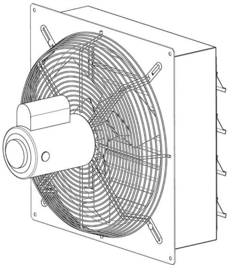
These models have a rugged, welded steel box housing with a powder coated finish and aluminum or plastic exhaust louvers that are supported by long life nylon bushings. The louvers open automatically when the fan starts up and close when the fan stops
text_image
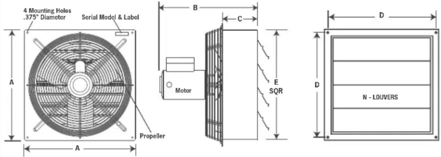
4 Mounting Holes .375" Diameter Serial Model & Label A A Propeller B C Motor E SQR D N - LOUVERS| Fan Size | A | B | C | D (c/c) | E | N | F |
| 8" | 13 1/4" | 11" | 4" | 12" | 10 3/4" | 2 | 11 X 11 |
| 10" | 15 1/4" | 11" | 4" | 14" | 12 3/4" | 2 | 13 X 13 |
| 12" | 17 1/4" | 17" | 6" | 16" | 14 3/4" | 3 | 15 X 15 |
| 14" | 19 1/4" | 17" | 6" | 18" | 16 3/4" | 3 | 17 X 17 |
| 16" | 21 1/4" | 17" | 6" | 20" | 18 3/4" | 4 | 19 X 19 |
| 18" | 23 1/4" | 15" | 6" | 22" | 20 3/4" | 4 | 21 X 21 |
| 20" | 25 1/4" | 18" | 6" | 24" | 22 3/4" | 5 | 23 X 23 |
| 24" | 29 1/4" | 18" | 6" | 28" | 26 3/4" | 5 | 27 X 27 |
| 30" | 35 1/4" | 19" | 6" | 34" | 32 3/4" | 16 | 33 X 33 |
| 36" | 41 1/4" | 18" | 6" | 40" | 38 3/4" | 20 | 39 X 39 |
| 42" | 47 1/4" | 18" | 6 3/4" | 46" | 44 3/4" | 24 | 45 X 45 |
| 48" | 53 1/4" | 19" | 6 3/4" | 52" | 50 5/8" | 26 | 51 X 51 |
EXPLOSION PROOF FANS:
Explosion proof fans are equipped with single speed explosion proof motors and aluminum blades so sparks cannot occur if a metal object obstructs the blade path. Explosion proof fans have the same quality welded steel box housing and heavy gauge welded guard as the standard fans. These fans should be used to ventilate hazardous areas. Locations are considered hazardous if the atmosphere contains or may contain gas, vapor, or dust in explosive quantities.
THE MOTOR AMBIENT TEMPERATURE IS NOT TO EXCEED +40°C OR -25°C UNLESS THE MOTOR NAMEPLATE SPECIFICALLY PERMITS ANOTHER VALUE. THE FOLLOWING TABLE INDICATES WHICH HAZARDOUS CLASSIFICATIONS CANARM EXPLOSION PROOF FANS DO AND DO NOT MEET.
Canarm explosion proof fans DO meet the following hazardous classifications.
CLASS 1, DIVISION 1 (GASES, VAPORS)
GROUP C Acetaldehyde, cyclopropane, diethlether, Ethylene, isoprene
GROUP D Acetone, acrylonitrile, ammonia, benzene, butane, ethylene dichloride, gasoline, hexane, methane, methanol, naphtha, propane, propylene styrene, toluene, vinyl, acetate, vinyl chloride, xylene
CLASS 2, DIVISION 1 (COMBUSTIBLE DUSTS)
GROUP F Carbon black, coke or coal dust
GROUP G Flour, starch or graindust
Canarm explosion proof fans DO NOT meet the following hazardous classifications.
CLASS 1, DIVISION 1 (GASES, VAPORS)
GROUP A Acetylene
GROUP B Butadiene, ethylene oxide, hydrogen, propylene oxide
CLASS 2, DIVISION 1 (COMBUSTIBLE DUSTS)
GROUP E Aluminum, magnesium and other metal dusts with similar characteristics
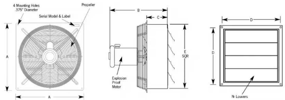
| Fan Size A | B C | D(c/c) | E | N | F | ||
| 12' 17 1/4' | 17' 6' 16 | 14 3/4" 3 | 15 X 15 | ||||
| 18' 23 1/4' | 15' 6' 22 | 20 3/4" 4 | 21 X 21 | ||||
| 24' 29 1/4' | 18' 6' 28 | 26 3/4" 5 | 27 X 27 |
INSTALLATION
Installation is fast and simple. A sturdy framed wall opening should be prepared in advance to the size indicated for your fan in the charts above. With lag bolts for wooden frames or nut, bolt and lock washers for steel frames, secure the fan using the four mounting holes provided, one in each corner of the fan.
ELECTRICAL CONNECTIONS

WARNING: BE SURE POWER IS OFF AT THE ELECTRICAL PANEL BEFORE WIRING.
WARNING: ALL ELECTRICAL WORK SHOULD BE PERFORMED BY A QUALIFIED ELECTRICIAN.
These fans are supplied with single, two or variable speed motors. Single and two speed motors are 120V only. Variable speed motors are dual voltage. All dual voltage motors are pre-wired at 240V in our factory. Rewire motor as per motor nameplate if running fan at 120V. Please see the motor nameplate for wiring diagram. Make electrical connections in motor connection box as per the motor nameplate. Two speed fans require a two speed control or 3 position toggle switch to change from high/ low/off. See wiring diagram with control for 2 speed wiring instructions.
If your unit contains the ECsmart Motor please follow these wiring diagrams:
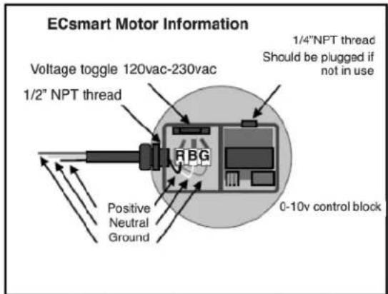
text_image
ECsmart Motor Information Voltage toggle 120vac-230vac 1/2" NPT thread Positive Neutral Ground FBG 1/4"NPT thread Should be plugged if not in use 0-10v control block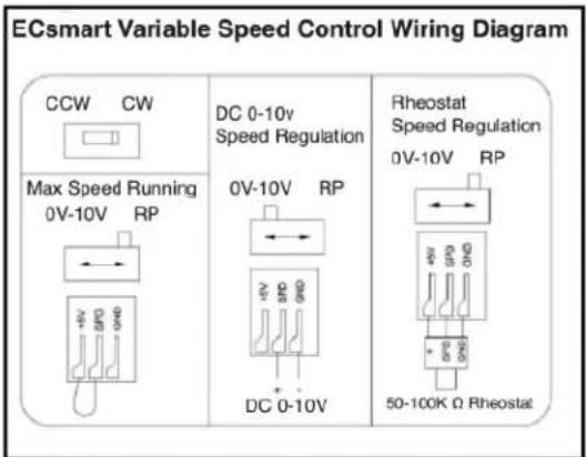
text_image
ECsmart Variable Speed Control Wiring Diagram CCW CW Max Speed Running 0V-10V RP DC 0-10v Speed Regulation 0V-10V RP DC 0-10V Rheostat Speed Regulation 0V-10V RP 50-100K Ω RheostatPlease contact Canarm Ltd. for any, and all questions related to electrical or control connections to our EC motors.
OPERATION
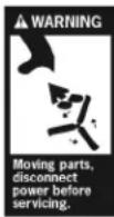
WARNING: VARIABLE SPEED FANS SHOULD HAVE THE MINIMUM SPEED SET TO OPEN LOUVERS AT LEAST ONE INCH FOR PROPER MOTOR COOLING AND TO PREVENT MOTOR FAILURE.
All fans are direct drive. Fans with variable speed motors can be operated as an energy efficient single speed fan or in variable operation with the proper controller. As mentioned above two speed fans require a two speed control or 3 position toggle switch to change from high speed to low and off.
WARNING: GUARDING SHOULD BE USED IF FANS ARE MOUNTED LOWER THAN SEVEN FEET (2 METRES) OFF FLOOR OR GROUND LEVEL.
ACCESSORIES
Canarm provides a complete line of manual and thermostatic controls. Canarm also offers wall mount exhaust shutter kits, replacement shutter sets, and weather protection hoods.
MAINTENANCE
MOTORS ARE EQUIPPED WITH AUTOMATIC OVERLOAD PROTECTION AND MAY RESTART WITHOUT WARNING. ALWAYS
DISCONNECT FROM POWER BEFORE ATTEMPTING SERVICE. Motor, blade and louvers should be kept clean of any buildup to prevent premature motor failure and to achieve proper performance. Automatic louvers should be kept operating freely. As with all mechanical equipment scheduled inspections should include checking that all hardware is secure and blade set screws are tight.
VENTILATEURS D'ÉVACUATION STANDARD
MANUEL DE L'USAGER
CANARM®
natural_image
Technical line drawing of a mechanical fan or vent with internal grid structure (no text or symbols)GARANTIE
CLASSE 1, DIVISION 1 (GAS ET VAPEURS)
GROUPE C ACÉTALDÉHYDE, CYCLOPROPANE, DIÉTHLÉTHER, ÉTHYLÈNE, ISOPRÈNE
GROUPE D ACÉTONE, ACRYLONITRILE, AMMONIAC, BENZÈNE, BUTANE, ÉTHYLÈNE DICHLORIDE, GAZOLINE, HEXANE, MÉTHANE, MÉTHANOL, NAPHTHA, PROPANE, PROPYLÈNE STYRÈNE, TOLUÈNE, VINYLE, ACÉTATE, VINYLE CHLORIDE, XYLÈNE
CLASSE 2, DIVISION 1 (POUSSIÈRES COMBUSTIBLES)
GROUPE F CARBON NOIR, COKE OU POUSSIÈRE DE CHARBON
GROUPE G FARINE, AMIDON OU POUSSIÈRE DE GRAIN
CLASSE 1, DIVISION 1 (GAS ET VAPEURS)
GROUPE A ACEETYLÈNE
GROUPE B BUTADIÈNE, OXYDE D'ÉTHYLÈNE, HYDROGÈNE, OXYDE DE PROPYLÈNE
CLASSE 2, DIVISION 1 (POUSSIÈRES COMBUSTIBLES)
GROUPE E ALUMINIUM, MAGNÉSIUM, ET AUTRES POUSSIÈRES DE MÉTAL AVEC DES CARACTERISTIQUES SIMILAIRES
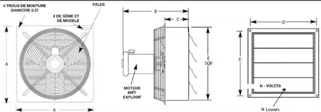
| Dimensions du Ventilateur | |||||||
| Ventilateur | A | B | C | D(c/c) | E | N | |
| 12' | 17 | 1/4' | 17' | 6' | 16' | 14 | 3/4' |
| 18' | 23 | 1/4' | 15' | 6' | 22' | 20 | 3/4' |
| 24' | 29 | 1/4' | 18' | 6' | 28' | 26 | 3/4' |