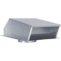
801642 - Extraction fan WOLF - Free user manual and instructions
Find the device manual for free 801642 WOLF in PDF.


| Product Type | Exhaust Fan |
| Brand | WOLF |
| Model | 801642 |
| Supply Voltage | 120 V |
| Rated Current | 2.4 A |
| Airflow | 600 CFM (cubic feet per minute) |
| Duct Diameter | 254 mm (10 in) |
| Installation Type | Roof or wall |
| Duct Material | Steel |
| Motor Protection | Thermal overload protection |
| Grounding | Yes |
| Use with range hood | Wolf wall hoods CTWH30/CTWH36, island hood IH4227 |
| Included accessories | Protection plate, bird screen, mounting screws |
| Maintenance | Frequent cleaning of fans and filters |
| Safety | Disconnect power before service, avoid plastic ducts |
| Country of origin | Not specified |
Frequently Asked Questions - 801642 WOLF
User questions about 801642 WOLF
0 question about this device. Answer the ones you know or ask your own.
Ask a new question about this device
Download the instructions for your Extraction fan in PDF format for free! Find your manual 801642 - WOLF and take your electronic device back in hand. On this page are published all the documents necessary for the use of your device. 801642 by WOLF.
USER MANUAL 801642 WOLF
- Use this unit only in the manner intended by the manufacturer. If you have questions, contact the manufacturer or your distributor.
- Before servicing or cleaning unit, switch power off at service panel and lock the service disconnecting means to prevent power from being switched on accidentally. When the service disconnecting means cannot be locked, securely fasten a prominent warning device, such as a tag, to the service panel.
- Installation work and electrical wiring must be done by a qualified person(s) in accordance with all applicable codes and standards, including fire-rated construction codes and standards.
- Sufficient air is needed for proper combustion and exhausting of gases through the flue (chimney) of fuel burning equipment to prevent backdrafting. Follow the heating equipment manufacturer's guidelines and safety standards such as those published by the National Fire Protection Association (NFPA), and the American Society for Heating, Refrigeration and Air Conditioning Engineers (ASHRAE), and the local code authorities.
- When cutting or drilling into wall or ceiling, do not damage electrical wiring and other hidden utilities.
- Ducted fans must always be vented to the outdoors.
- Do not use this unit with an additional speed control device.
- To reduce the risk of fire, use only steel ductwork.
- This unit must be grounded.
TO REDUCE THE RISK OF A COOKTOP GREASE FIRE:
- Never leave surface units unattended at high settings. Boilovers cause smoking and greasy spillovers that may ignite. Heat oils slowly on low or medium settings.
- Always turn hood ON when cooking at high heat or when cooking flaming foods.
- Clean ventilating fans frequently. Grease should not be allowed to accumulate on fan or filter.
- Use proper pan size. Always use cookware appropriate for the size of the surface element.
TO REDUCE THE RISK OF INJURY TO PERSONS IN THE EVENT OF A COOKTOP GREASE FIRE, OBSERVE THE FOLLOWING:\*
- SMOTHER FLAMES with a close-fitting lid, cookie sheet, or metal tray, then turn off the burner. BE CAREFUL TO PREVENT BURNS. If the flames do not go out immediately, EVACUATE AND CALL THE FIRE DEPARTMENT.
- NEVER PICK UP A FLAMING PAN - You may be burned.
- DO NOT USE WATER, including wet dishcloths or towels - violent steam explosion will result.
- Use an extinguisher ONLY if:
A. You know you have a Class ABC extinguisher and you already know how to operate it.
B. The fire is small and contained in the area where it started.
C. The fire department is being called.
D. You can fight the fire with your back to an exit.
* Based on "Kitchen Fire Safety Tips" published by NFPA.
CAUTION

- For general ventilating use only. Do not use to exhaust hazardous or explosive materials and vapors.
- To avoid motor bearing damage and noisy and/or unbalanced impellers, keep drywall spray, construction dust, etc. off power unit.
- Your ventilator motor has a thermal overload which will automatically shut off the motor if it becomes overheated. The motor will restart when it cools down. If the motor continues to shut off and restart, have the hood serviced.
- Please read specification label on product for further information and requirements.
SPECIFICATIONS
| MODEL | VOLTS AM | MPS CFM | DUCT S | ZE |
| 801640 1 | 20 2.4 600 | 10 "DIA. |
PLAN THE INSTALLATION
- Locate the ventilator so the length of the duct run and number of elbows and transitions needed are kept to a minimum.
- Where possible, ventilator should be located between wall studs or roof rafters.
- Avoid pipes, wires, or other ductwork that may be running through the wall.
- Be sure that there is enough space for any transitions that may be needed between the ventilator and the connecting ductwork.
- For best performance, locate transitions nearest to ventilator.
ROOF MOUNT INSTALLATION
For use with Wolf CTWH30/CTWH36 wall mount, IH4227 island chimney hoods, 10" tall & 30" wide x 18" tall wall hoods.
PREPARE THE ROOF
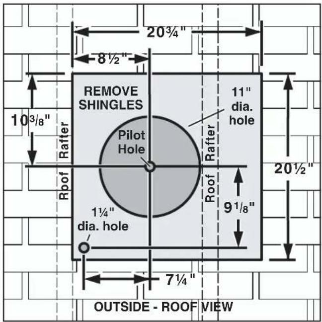
From inside the attic space:
q1 Drill a PILOT HOLE up through the roof, 8½" from the inside edge of a ROOF RAFTER.
From outside - on the roof:
q2 Measure and mark the 20^3/4 " x 20^1/2 " rectangle. Cut and remove only the shingles inside this rectangle.
q3 Measure and mark the 11" DIAMETER HOLE and the 1¼" DIAMETER HOLE. Cut these holes all the way through the roof.
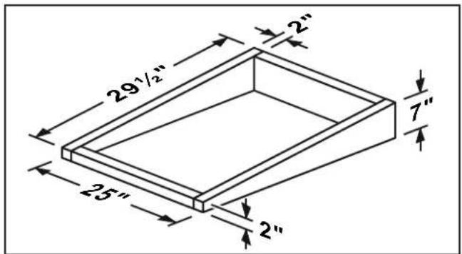
For flat roof installations:
q4 Build a curb that will mount the blower at a minimum pitch of 2/12. Discharge end of the blower should be pointed away from prevailing winds.
WIRE THE VENTILATOR
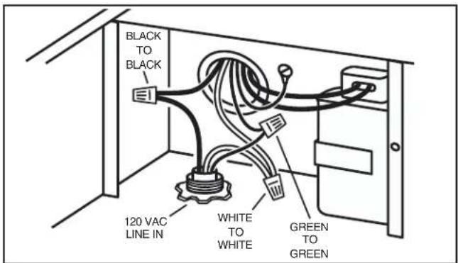
q5 Remove 7 COVER SCREWS and lift off ventilator cover. Remove BIRD SCREEN and WIRING COVER.
q6 Feed the electric power cable through the 1¼" DIAMETER HOLE and connect cable to ventilator with a proper connector for the type of cable being used.
q7 Connect BLACK TO BLACK, WHITE TO WHITE, and the GREEN TO GREEN or bare wire. Replace wiring cover.
INSTALL THE VENTILATOR
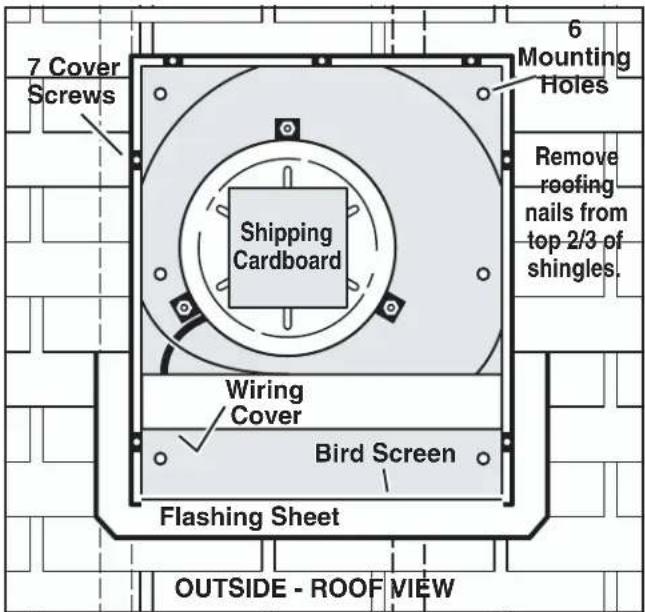
q8 Remove SHIPPING CARDBOARD from blower wheel. q9 Remove roofing nails from top 2/3 of shingles around cut-out area.
q10 Slide the ventilator's FLASHING SHEET up and under the loosened shingles until ventilator's discharge collar fits into 11" diameter hole.
q11 Use the 6 screws (provided) to attach the ventilator to the roof. 6 MOUNTING HOLES are provided.
q12 Seal the screw heads, loosened shingles, and edges of the flashing sheet, with a good grade of roofing cement.
q13 Check for free movement of the spring-loaded damper, re-install BIRD SCREEN and ventilator cover. Turn on power and check operation.
WALL MOUNT INSTALLATION
For use with Wolf CTWH30/CTWH36 wall mount, IH4227 island chimney hoods, 10" tall & 30" wide x 18" tall wall hoods.
PREPARE THE WALL
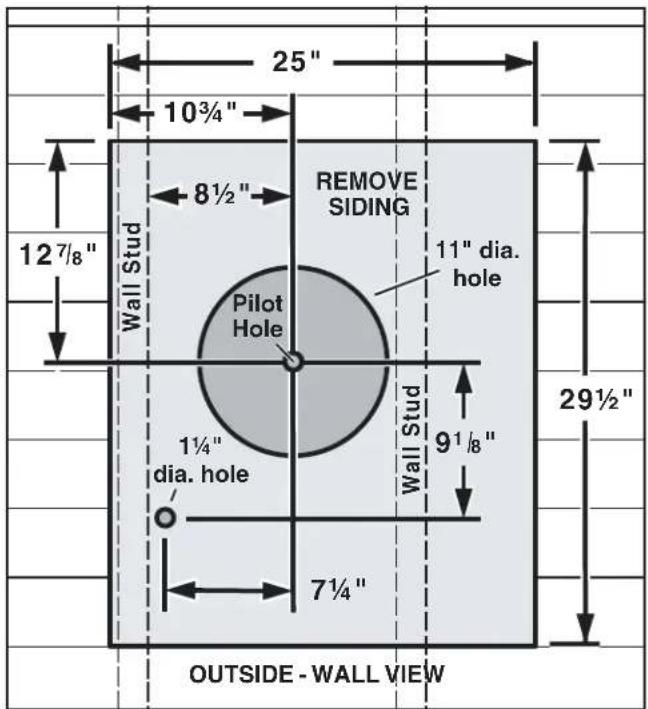
From inside the wall:
q1 Drill a PILOT HOLE through the wall, 8½" from the inside edge of a WALL STUD.
From outside - on the wall:
q2 Measure and mark the 25" x 29½" rectangle. Cut and remove only the siding inside this rectangle.
q3 Measure and mark the 11" DIAMETER HOLE and the 1¼" DIAMETER HOLE. Cut these holes all the way through the wall.
WIRE THE VENTILATOR
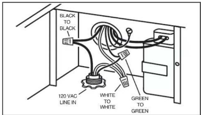
q4 Remove 7 COVER SCREWS and lift off ventilator cover. Remove BIRD SCREEN and WIRING COVER.
q5 Feed the electric power cable through the 1¼" DIAMETER HOLE and connect cable to ventilator with a proper connector for the type of cable being used.
q6 Connect BLACK TO BLACK, WHITE TO WHITE, and the GREEN TO GREEN or bare wire. Replace wiring cover.
INSTALL THE VENTILATOR
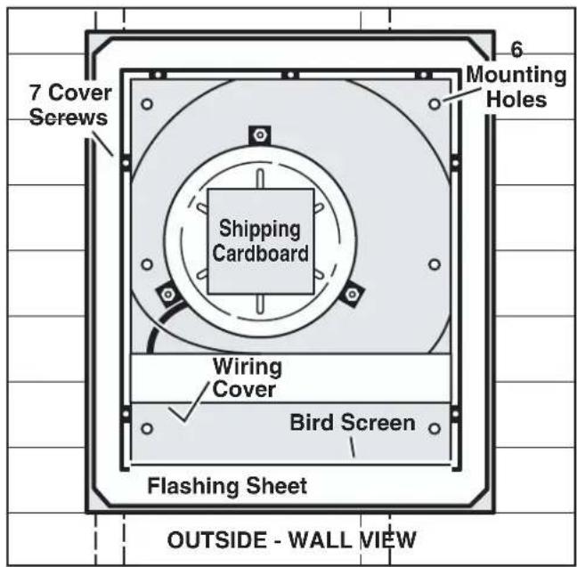
g7 Remove SHIPPING CARDBOARD from blower wheel.
q8 Place ventilator on wall so that ventilator's discharge collar fits into 11" diameter hole.
q9 Use the 6 screws (provided) to attach the ventilator to the wall. 6 MOUNTING HOLES are provided.
q10 Seal the screw heads and edges of the flashing sheet with a good grade of roofing cement.
q11 Check for free movement of the spring-loaded damper, re-install BIRD SCREEN and ventilator cover. Turn on power and check operation.
ATTACH POWER CORD TO HOOD
Some hoods require the use of a separate power cord and strain relief bushing (included), for proper wiring of exterior blowers. Please refer to the hood manual for proper installation instructions.
Brand : WOLF
Model : 801642
Category : Extraction fan