
GEX12V-5 Professional - Sander BOSCH - Free user manual and instructions
Find the device manual for free GEX12V-5 Professional BOSCH in PDF.

| Product type | Random orbit sander |
| Brand | Bosch |
| Model | GEX12V-5 Professional |
| Disc diameter | 125 mm (5 in) |
| Power source | 12 V lithium-ion battery pack (not included) |
| Variable speed | 6-position dial (1 slow to 6 fast) |
| Orbit | Random (prevents swirl marks) |
| Maximum no-load speed | Up to 12,000 orbits/min (according to nameplate) |
| Dust extraction system | Integrated dust bag; adaptable to vacuum cleaner (VAC024/VAC002 adapter optional) |
| Weight | Approx. 1.5 kg (with battery pack) |
| Dimensions (L × W × H) | Approx. 290 × 130 × 160 mm |
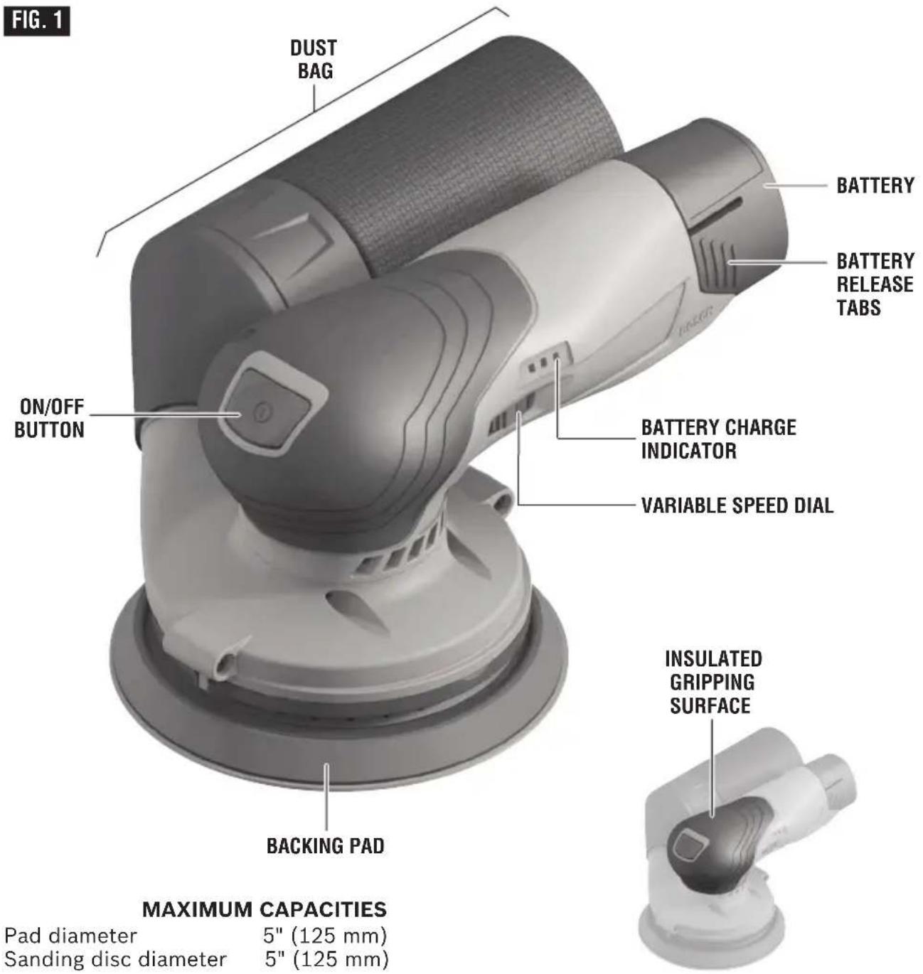
| Insulated gripping surface | Yes, for comfort and safety |
| Backing pad types | Soft, medium (included), hard; soft adhesive optional |
| Compatible accessories | Hook-and-loop (velcro) or adhesive abrasive discs, polishing pad, polishing bonnet |
| Warranty | 1 year (limited); replacement parts available |
| Maintenance | Regular emptying of dust bag; cleaning ventilation slots; professional lubrication |
| Safety | GFCI-protected power supply recommended; wear PPE (goggles, mask, hearing protection) |
| Spare parts and repairability | Backing pad, damping ring, dust bag available; repair by Bosch authorized service center |
| General information | Professional use; ideal for sanding wood, metal, paint, polishing |
Frequently Asked Questions - GEX12V-5 Professional BOSCH
User questions about GEX12V-5 Professional BOSCH
0 question about this device. Answer the ones you know or ask your own.
Ask a new question about this device
Download the instructions for your Sander in PDF format for free! Find your manual GEX12V-5 Professional - BOSCH and take your electronic device back in hand. On this page are published all the documents necessary for the use of your device. GEX12V-5 Professional by BOSCH.
USER MANUAL GEX12V-5 Professional BOSCH
natural_image
Silhouette of a person reading a book inside a circle (no text or symbols)Operating/Safety Instructions Consignes d'utilisation/de sécurité Instrucciones de funcionamiento y seguridad
GEX12V-5

natural_image
3D rendering of a mechanical robotic device with no visible text or symbols
BOSCH
Call Toll Free for Consumer Information and Service Locations Pour obtenir des informations et les adresses de nos centres de service après-vente, appelez ce numéro gratuit Llame gratis para obtener información para el consumidor y ubicaciones de servicio
1-877-BOSCH99 (1-877-267-2499) www.boschtools.com
For English Version See page 2
| Safety SymbolsThe definitions below describe the level of severity for each signal word.Please read the manual and pay attention to these symbols. | |
 | This is the safety alert symbol. It is used to alert you to potential personal injury hazards. Obey all safety messages that follow this symbol to avoid possible injury or death. |
 | DANGER indicates a hazardous situation which, if not avoided, will result in death or serious injury. |
 | WARNING indicates a hazardous situation which, if not avoided, could result in death or serious injury. |
 | CAUTION indicates a hazardous situation which, if not avoided, could result in minor or moderate injury. |
General Power Tool Safety Warnings
WARNING
Read all safety warnings, instructions, illustrations and specifications provided with this power tool. Failure to follow all instructions listed below
may result in electric shock, fire and/or serious injury.
SAVE ALL WARNINGS AND INSTRUCTIONS FOR FUTURE REFERENCE
The term “power tool” in the warnings refers to your mains-operated (corded) power tool or battery-operated (cordless) power tool.
1. Work area safety
a. Keep work area clean and well lit.
Cluttered or dark areas invite accidents.
b. Do not operate power tools in explosive atmospheres, such as in the presence of flammable liquids, gases or dust. Power tools create sparks which may ignite the dust or fumes.
c. Keep children and bystanders away while operating a power tool.
Distractions can cause you to lose control.
2. Electrical safety
a. Power tool plugs must match the outlet. Never modify the plug in any way. Do not use any adapter plugs with earthed (grounded) power tools. Unmodified plugs and matching outlets will reduce risk of electric shock.
b. Avoid body contact with earthed or grounded surfaces, such as pipes, radiators, ranges and refrigerators. There is an increased risk of electric shock if your body is earthed or grounded.
c. Do not expose power tools to rain or
wet conditions. Water entering a power tool will increase the risk of electric shock.
d. Do not abuse the cord. Never use the cord for carrying, pulling or unplugging the power tool. Keep cord away from heat, oil, sharp edges or moving parts. Damaged or entangled cords increase the risk of electric shock.
e. When operating a power tool outdoors, use an extension cord suitable for outdoor use. Use of a cord suitable for outdoor use reduces the risk of electric shock.
f. If operating a power tool in a damp location is unavoidable, use a Ground Fault Circuit Interrupter (GFCI) protected supply. Use of an GFCI reduces the risk of electric shock.
3. Personal safety
a. Stay alert, watch what you are doing and use common sense when operating a power tool. Do not use a power tool while you are tired or under the influence of drugs, alcohol or medication. A moment of inattention while operating power tools may result in serious personal injury.
General Power Tool Safety Warnings
b. Use personal protective equipment.
Always wear eye protection. Protective equipment such as dust mask, non-skid safety shoes, hard hat, or hearing protection used for appropriate conditions will reduce personal injuries.
c. Prevent unintentional starting. Ensure
the switch is in the off-position before connecting to power source and / or battery pack, picking up or carrying the tool. Carrying power tools with your finger on the switch or energizing power tools that have the switch on invites accidents.
d. Remove any adjusting key or wrench
before turning the power tool on. A wrench or a key left attached to a rotating part of the power tool may result in personal injury.
e. Do not overreach. Keep proper footing
and balance at all times. This enables better control of the power tool in unexpected situations.
f. Dress properly. Do not wear loose
clothing or jewelry. Keep your hair, clothing and gloves away from moving parts. Loose clothes, jewelry or long hair can be caught in moving parts.
g. If devices are provided for the
connection of dust extraction and collection facilities, ensure these are connected and properly used. Use of dust collection can reduce dust-related hazards.
h. Do not let familiarity gained from
frequent use of tools allow you to become complacent and ignore tool safety principles. A careless action can cause severe injury within a fraction of a second.
4. Power tool use and care
a. Do not force the power tool. Use the correct power tool for your application.
The correct power tool will do the job better and safer at the rate for which it was designed.
b. Do not use the power tool if the switch
does not turn it on and off. Any power tool that cannot be controlled with the switch is dangerous and must be repaired.
c. Disconnect the plug from the power
source and/or remove the battery pack, if detachable, from the power tool before making any adjustments,
changing accessories, or storing power tools. Such preventive safety measures reduce the risk of starting the power tool accidentally.
d. Store idle power tools out of the reach of children and do not allow persons unfamiliar with the power tool or these instructions to operate the power tool. Power tools are dangerous in the hands of untrained users.
e. Maintain power tools and accessories. Check for misalignment or binding of moving parts, breakage of parts and any other condition that may affect the power tool's operation. If damaged, have the power tool repaired before use. Many accidents are caused by poorly maintained power tools.
f. Keep cutting tools sharp and clean.
Properly maintained cutting tools with sharp cutting edges are less likely to bind and are easier to control.
g. Use the power tool, accessories and tool bits etc. in accordance with these instructions, taking into account the working conditions and the work to be performed. Use of the power tool for operations different from those intended could result in a hazardous situation.
h. Keep handles and grasping surfaces dry, clean and free from oil and grease.
Slippery handles and grasping surfaces do not allow for safe handling and control of the tool in unexpected situations.
5. Battery tool use and care
a. Recharge only with the charger specified by the manufacturer. A charger that is suitable for one type of battery pack may create a risk of fire when used with another battery pack.
b. Use power tools only with specifically designated battery packs. Use of any other battery packs may create a risk of injury and fire.
c. When battery pack is not in use, keep it away from other metal objects like paper clips, coins, keys, nails, screws, or other small metal objects that can make a connection from one terminal to another. Shorting the battery terminals together may cause burns or a fire.
d. Under abusive conditions, liquid may
General Power Tool Safety Warnings
be ejected from the battery, avoid contact. If contact accidentally occurs, flush with water. If liquid contacts eyes, additionally seek medical help. Liquid ejected from the battery may cause irritation or burns.
e. Do not use a battery pack or tool that is damaged or modified. Damaged or modified batteries may exhibit unpredictable behavior resulting in fire, explosion or risk of injury.
f. Do not expose a battery pack or tool to fire or excessive temperature. Exposure to fire or temperature above 265 °F may cause explosion.
g. Follow all charging instructions and do not charge the battery pack or tool
outside the temperature range specified in the instructions. Charging improperly or at temperatures outside the specified range may damage the battery and increase the risk of fire.
6. Service
a. Have your power tool serviced by a qualified repair person using only identical replacement parts. This will ensure that the safety of the power tool is maintained.
b. Never service damaged battery packs. Service of battery packs should only be performed by the manufacturer or authorized service providers.
Safety Rules for Random Orbital Sanders
a. Use clamps or another practical way to secure and support the workpiece to a stable platform. Holding the work by your hand or against the body leaves it unstable and may lead to loss of control.
b. Remove battery before changing accessories. Accidental start-ups may occur if battery is installed while changing an accessory.
c. If your tool is equipped with a dust bag, empty it frequently and after completion of sanding. Be extremely careful of dust disposal, materials in fine particle form may be explosive. Do not throw sanding dust on an open fire. Spontaneous combustion may, in time, result from mixture of oil or water with dust particles.
d. Always wear eye protection and a dust mask for dusty applications and when sanding overhead. Sanding particles can be absorbed by your eyes and inhaled easily and may cause health complications.
e. Do not wet sand with this sander. Liquids entering the motor housing is an electrical shock hazard.
f. Do not use PSA pad on random orbit sanders whose speed exceeds 12,000/min. Exceeding the maximum operating speed of pad may cause pad to rupture or fly apart during use striking user or bystanders.
g. Do not use sandpaper intended for larger sanding pads. Larger sandpaper will extend beyond the sanding pad causing snagging, tearing of the paper or kick-back. Extra paper extending beyond the sanding pad can also cause serious lacerations.
h. Clamp or secure workpiece when sanding. Clamping the workpiece prevents it from being ejected from under the sander and leaves both hands to control the tool.
Additional Safety Warnings
GFCI and personal protection devices like electrician's rubber gloves and footwear will further enhance your personal safety.
Do not use AC only rated tools with a DC power supply. While the tool may appear to work, the electrical components of the AC rated tool are likely to fail and create a hazard to the operator.
Keep handles dry, clean and free from oil and grease. Slippery hands cannot safely control the power tool.
Develop a periodic maintenance schedule for your tool. When cleaning a tool be careful not to disassemble any portion of the tool since internal wires may be misplaced or pinched or safety guard return springs may be improperly mounted. Certain cleaning agents such as gasoline, carbon tetrachloride, ammonia, etc. may damage plastic parts.
Risk of injury to user. The power cord must only be serviced by a Bosch Factory Service Center or Autho rized Bosch Service Station.
WARNING
Some dust created by power sanding, sawing, grinding, drilling, and other construction activities contains chemicals known to cause cancer, birth defects or other reproductive harm. Some examples of these chemicals are:
- Lead from lead-based paints,
- Crystalline silica from bricks and cement and other masonry products, and
- Arsenic and chromium from chemically-treated lumber.
Your risk from these exposures varies, depending on how often you do this type of work. To reduce your exposure to these chemicals: work in a well ventilated area, and work with approved safety equipment, such as those dust masks that are specially designed to filter out microscopic particles.
Symbols
Important: Some of the following symbols may be used on your tool. Please study them and learn their meaning. Proper interpretation of these symbols will allow you to operate the tool better and safer.
| Symbol Designation / Explanation | |
| V Volts (voltage) | |
| Ah Amp hour (measurement of battery capacity) | |
| A Amperes (current) | |
| Hz Hertz (frequency, cycles per second) | |
| W Watt (power) | |
| kg Kilograms (weight) | |
| min Minutes (time) | |
| s Seconds (time) | |
| ∅ | Diameter (size of drill bits, grinding wheels, etc.) |
| n_0 | No load speed (rotational speed at no load) |
| n Rated | speed (maximum attainable speed) |
| .../min | Revolutions or reciprocation per minute (revolutions, strokes, surface speed, orbits etc. per minute) |
| 0 Off position (zero speed, zero torque...) | |
| 1, 2, 3, ...I, II, III, | Selector settings (speed, torque or position settings. Higher number means greater speed) |
| 0 | Infinitely variable selector with off (speed is increasing from 0 setting) |
| → | Arrow (action in the direction of arrow) |
| ~ | Alternating current (type or a characteristic of current) |
| --- | Direct current (type or a characteristic of current) |
| ~ | Alternating or direct current (type or a characteristic of current) |
| ☐ | Class II construction (designates double insulated construction tools) |
| ⊕ | Earthing terminal (grounding terminal) |
Symbols
Important: Some of the following symbols may be used on your tool. Please study them and learn their meaning. Proper interpretation of these symbols will allow you to operate the tool better and safer.
| Symbol Designation / Explanation | |
 | Alerts user to read manual |
 | Alerts user to wear eye protection |
 | Alerts user to wear respiratory protection |
 | Alerts user to wear hearing protection |
 | This symbol designates that this tool is listed by Underwriters Laboratories. |
 | This symbol designates that this tool is listed by Underwriters Laboratories, to United States and Canadian Standards. |
 | This symbol designates that this tool is listed by the Canadian Standards Association. |
 | This symbol designates that this tool is listed by the Canadian Standards Association, to United States and Canadian Standards. |
 | This symbol designates that this tool is listed by the Intertek Testing Services, to United States and Canadian Standards. |
 | Designates Li-ion battery recycling program |
Functional Description and Specifications
WARNING
Disconnect the plug from the power source before making any assembly, adjustments or changing accessories. Such preventive safety
measures reduce the risk of starting the tool accidentally.
Cordless Random Orbit Sander
Allowed ambient temperature
| During charging | 32...95 °F (0...+35 °C) |
| During operation | 5...122 °F (-15...+50 °C) |
| During storage | 32...122 °F (0...+50 °C) |
NOTE: For tool specifications refer to the nameplate on your tool.
Battery Packs / Chargers:
Please refer to the battery/charger list, included with your tool.
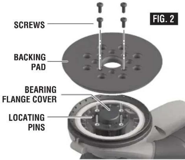
Backing Pad Installation
The random orbit sander is equipped with a backing pad of medium hardness, which is suitable for general service. Hard and soft pads are available for other purposes, and in general are used as follows;
Soft pad - Polishing or sanding large or curved surfaces.
Medium pad - All purpose general sanding and polishing.
Hard pad - Heavy sanding on flat surfaces, especially with coarser abrasives.
To change backing pad, hold pad firmly and remove the four screws that secure the backing pad (using a T20 bit) and remove old pad. Align new pad over bearing flange cover and locating pins on drive spindle, replace screws and securely tighten. Damaged or worn backing pads must be replaced immediately (Fig. 2).
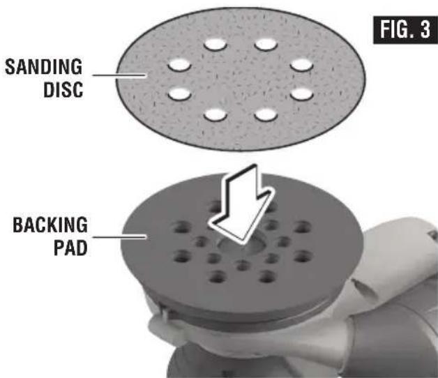
Installing Accessories
The random orbit sander uses hook-and-loop backed accessories, which firmly grip the pad when applied with moderate pressure. To change the accessory, merely peel off the old accessory, remove dust from the pad if necessary, and press the new accessory in place (Fig. 3). Be sure to align the sanding disc holes with the holes in the backing pad to allow the dust extraction system to function.
After considerable service the pad surface will become worn, and the pad must be replaced when it no longer offers a firm grip. If you are experiencing premature wearout of the pad hooks, it may be due to pressure being applied to the tool during operation.
PSA Backing Pad Accessories
The optional RS036 soft PSA backing pad can be used with PSA backed accessories with pressure sensitive adhesive.
To change accessory, peel protective sheet from the back of accessory. Align accessory with backing pad and press firmly in place. To remove, lift an edge of accessory with your finger nail and peel it off the backing pad.
NOTE: Do not store tool with sanding disc on pad, as sanding creates heat which increases the adhesive bond. If the disc is left in place it may become very difficult to remove.
Assembly
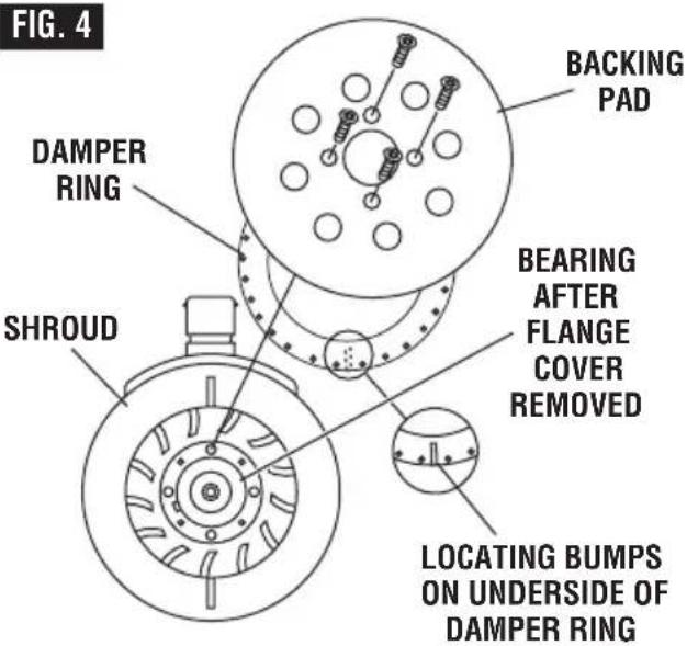
Backing Pad Damper
Your tool is equipped with an integrated backing pad damper ring. This damper reduces the no-load speed, which helps prevent swirl marks on the workpiece surface and provides uniform finishing.
NOTE: If you notice steadily increasing no-load speed, this indicates that the damper ring is worn and needs to be replaced.
To replace damper ring, remove backing pad as described in "Backing Pad Installation" and remove worn damper ring by pulling firmly out of locating groove. Loosen the two screws on shroud just enough so you can separate shroud approximately 1/4 inch. Align locating bumps on damper ring with cut outs in shroud and depress ring with thumbs until shroud seats into groove completely around ring, then tighten screws (Fig. 4).
Re-attach backing pad as described in "Backing Pad Installation".
IMPORTANT: Ring should not have bends or ripples when correctly seated.
Dust Collection
Dust Bag
The integral dust extraction system collects sanding dust in the dust bag supplied with your sander. For maximum efficiency, the dust bag should be emptied frequently during operation.
WARNING
Your tool is equipped with a dust bag: empty it
frequently, after completion of sanding, and before storing the sander. Be extremely careful of dust disposal, materials in fine particle form may be explosive. Do not throw sanding dust on an open fire. Combustion from mixture of varnishes, lacquers, polyurethane, oil or water with dust particles can occur if there is a static discharge, spark introduced in the box, or excessive heat.
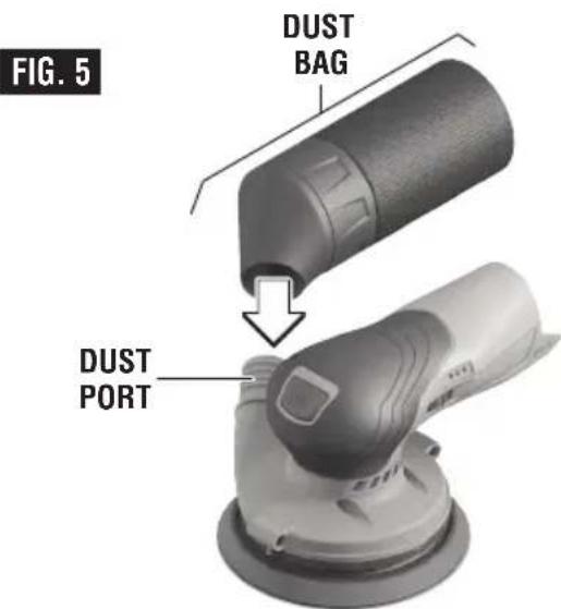
REMOVING AND INSTALLING DUST BAG
To remove dust bag: Twist the bag left or right and simply pull away from the tool.
To install dust bag: align dust port with hole in bag and push bag onto tool until it locks into place (Fig. 5).
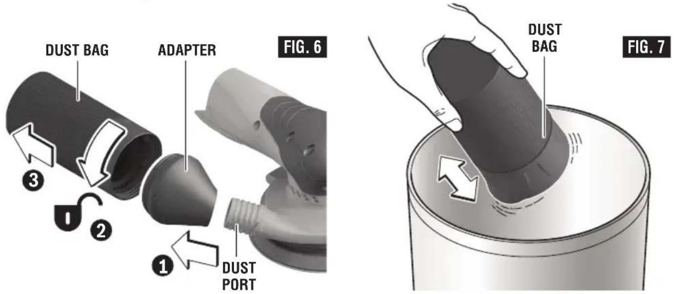
CLEANING AND EMPTYING THE DUST BAG
Before emptying the dust bag, it is recommended to loosen dust from the bag by gently tapping it against a solid surface. To empty bag, hold bag and maintain a firm grip. Unscrew the bag from the plastic adapter and pull them apart (Fig. 6). Then, shake out the bag over a suitable waste bin
(Fig. 7). Knock excess dust out of the bag, or remove dust with your fingers or a soft brush. You may notice that all the dust may not come out of the bag. This will not affect sanding performance but will reduce dust collection efficiency.
NOTE: Do not wash the dust bag with soap and water. Dust may become more firmly lodged in the pores, which will reduce dust collection.
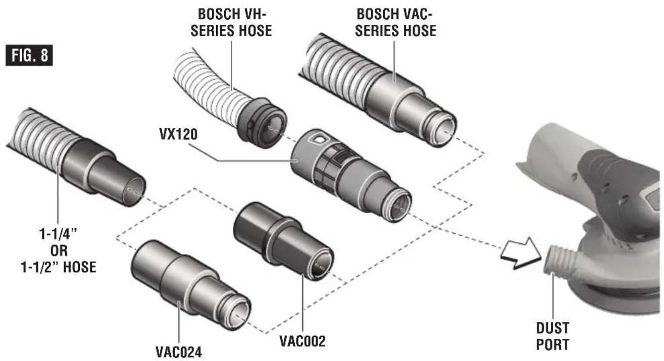
ATTACHING A VACUUM CLEANER
Dust collection can also be achieved by attaching the tool to a vacuum cleaner / dust extractor, hose and adapter, if necessary (all sold separately).
- Attach the hose to the vacuum cleaner / dust extractor.
-
Attach the hose to the tool's dust port in one of the following ways (Fig. 8):
-
Bosch VH-series hoses - The VX120 hose adapter is required (included with VH-series hoses).
- Other 35mm and 22mm hoses, such as the Bosch VAC-series hoses - Connect hose directly to the tool.
- Common 1-1/4" or 1-1/2" hoses - The Bosch VAC002 or VAC024 adapter is required.
Operating Instructions
On/Off Button
TO TURN THE TOOL "ON": depress the On/Off button.
TO TURN THE TOOL "OFF": depress the On/Off button.
See START OF SANDING on page 13.
Variable Speed with Dial Setting
Your sander is also equipped with a variable speed dial (Fig. 1). The sander's orbital pad speed can be preset from zero to maximum nameplate OPM by rotating the dial in the housing. The dial may be set on or between any of six positions (1=low through 6=high).
The following table may be used as a general guide for abrasive and backing pad selection, but the best results will be obtained by sanding a test sample of the workpiece first.
| Material | Switch setting | Backing pad | Grit size |
| rough/finish | rough/finish | ||
| Woods: | |||
| softwoods 4 | / 6 soft 60 / 2 | 40 | |
| hardwoods 4 | / 6 medium 6 | 0 / 180 | |
| veneers 4 | medium 240 / 3 | 20 | |
| Metals: | |||
| steel 4 | medium 60 / 240 | ||
| stainless | 4 | medium 120 / 240 | |
| aluminum 4 | / 6 medium 80 | / 240 | |
| rust spots 6 | soft | 60 / 120 | |
| Paintwork: | |||
| sanding | 2 / 3 | medium 180 / 400 | |
| scratches | 4 / 6 | hard | 120 / 240 |
| stripping | 4 | medium 40 / 60 | / 80 |
Your sander was designed to sand in small or confined areas. Its small size and light weight makes it ideal for overhead work.
You may grip the tool on top of the tool with either the battery behind your hand or in front of you hand (Fig. 9).

natural_image
Two hands operating a power shaver and a cylindrical device, labeled 'FIG. 9' (no text or symbols on the devices themselves)Tool Tips
Selecting Sanding Discs
Open-coat aluminum oxide sanding discs are recommended for most wood or metal sanding applications, as this synthetic material cuts quickly and wears well. Some applications, such as plastics, glass, or stone require silicon carbide discs, which have a very sharp cutting edge. For best results, use Bosch sanding and polishing accessories, which are of superior quality and are carefully selected to produce professional quality results with your sander.
An alternative to standard sanding discs is to use a SandNet ^™ connection pad and SandNet ^™ mesh sanding discs.
Start of Sanding
With the workpiece firmly secured, first place the sander's pad on the work surface, then switch the tool on.
DO NOT start the tool and bring it up to speed before applying to the work
DO NOT apply excessive pressure when switch the tool on (or at any other time)
Either method will likely create swirl marks.
Applying excessive pressure upon start-up will also shorten the life of the switch.
Sanding Action
In general, higher speeds will give the best results. If faster removal is desired, DO NOT APPLY PRESSURE ON THE TOOL; use a coarser grade of abrasive. Move the sander in long sweeping strokes, parallel to the grain using some lateral motion to overlap the strokes by as much as 75%. The random orbit action allows cross-grain sanding, but be careful not to tilt the sander near edges, or undesirable rounding may result.
Sanding Sequence
If the surface is rough, begin with coarser grits and then complete the surfacing with medium and fine abrasives. Because the random orbit action is so effective, it is often possible to begin sanding with a medium grit disc and go directly to fine finishing. To avoid uneven results, do not skip more than one grit size when going from coarser to finer, and do not sand in one area for too long.
Removal of Sander
To help prevent swirl marks when the job is completed, gently lift the tool from the work surface, then switch the tool off. Operating in this manner will also prolong the switch life.
Polishing
For most polishing, the medium backing pad will give the best results. The random orbit sander may be fitted with an optional foam buffing pad or polishing bonnet to polish or remove scratches from painted or finished surfaces, plastics, and even glass. The tool is operated in much the same way as when sanding, but the following points should be observed;
Apply the compound to the surface, and use the sponge applicator pad with light pressure and a circular motion to remove scratches and restore weathered finishes. Use only as much compound as necessary, and clean the sponge frequently during use.
When initial polishing is completed, wipe away any excess compound with a soft towel, and then polish the surface to its final finish with the polishing bonnet. Use smooth overlapping strokes for best results.
It is important to note that the orbit speed of the random orbit sander is not the same as the RPM of a standard right-angle polisher. The random orbit action is much like a powerful hand polishing action, and therefore does not have the high speeds at the edge of the pad which can burn the work surface. For this reason, it is possible to select a higher OPM for the random orbit sander than the recommended RPM for a standard polisher. Practice on a hidden area or test surface until you have determined the tool is suitable for your polishing application.
Clean the buffing pad and polishing bonnet with mild detergents and warm water. DO NOT use solvents.
Maintenance
WARNING
To avoid accidents always dis connect the tool from the power supply before cleaning or performing any main tenance.
Service
WARNING
Preventive maintenance performed by
unauthorized per so n nel may result in misplacing of internal wires and components which could cause serious hazard. We recommend that all tool service be performed by a Bosch Factory Service Center or Autho rized Bosch Service Station.
Tool Lubrication
Your Bosch tool has been properly lubricated and is ready to use. It is recommended that tools with gears be regreased with a special gear lubricant at every brush change.
Batteries
Be alert for battery packs that are nearing their end of life. If you notice decreased tool performance or significantly shorter running
time between charges then it is time to replace the battery pack. Failure to do so can cause the tool to operate improperly or damage the charger.
Bearings
Bearings which become noisy (due to heavy load or very abrasive material cutting) should be replaced at once to avoid overheating or motor failure.
Cleaning
CAUTION
Certain cleaning agents and sol vents damage
plastic parts. Some of these are: gasoline, carbon tetrachloride, chlorinated cleaning solvents, ammonia and house hold detergents that contain ammonia.
Ventilation openings and switch levers must be kept clean and free of foreign matter. Do not attempt to clean by inserting pointed objects through openings.
Accessories and Attachments
Allowed ambient temperature
| During charging | 32...95°F (0...+35°C) |
| During operation | 5...122°F (-15...+50°C) |
| During storage | 32...122°F (0...+50°C) |
natural_image
Two hands operating a mechanical device with rollers, labeled 'FIG. 9' (no text on device or background)Conseils pratiques
SÉLECTION DES DISQUES DE PONÇAGE
Allowed ambient temperature
| durante el proceso de carga | 32...95°F (0...+35°C) |
| durante la utilización | 5...122°F (-15...+50°C) |
| durante la almacenamiento | 32...122°F (0...+50°C) |
natural_image
Illustration of two hands operating a sanding machine, no text or symbols presentRobert Bosch Tool Corporation ("Seller") warrants to the original purchaser only, that all BOSCH portable and benchtop power tools will be free from defects in material or workmanship for a period of one year from date of purchase. SELLER'S SOLE OBLIGATION AND YOUR EXCLUSIVE REMEDY under this Limited Warranty and, to the extent permitted by law, any warranty or condition implied by law, shall be the repair or replacement of parts, without charge, which are defective in material or workmanship and which have not been misused, carelessly handled, or misrepaired by persons other than Seller or Authorized Service Station. To make a claim under this Limited Warranty, you must return the complete portable or benchtop power tool product, transportation prepaid, to any BOSCH Factory Service Center or Authorized Service Station. For Authorized BOSCH Power Tool Service Stations, please refer to your phone directory.
THIS LIMITED WARRANTY DOES NOT APPLY TO ACCESSORY ITEMS SUCH AS CIRCULAR SAW BLADES, DRILL BITS, ROUTER BITS, JIGSAW BLADES, SANDING BELTS, GRINDING WHEELS AND OTHER RELATED ITEMS.
ANY IMPLIED WARRANTIES SHALL BE LIMITED IN DURATION TO ONE YEAR FROM DATE OF PURCHASE. SOME STATES IN THE U.S., SOME CANADIAN PROVINCES DO NOT ALLOW LIMITATIONS ON HOW LONG AN IMPLIED WARRANTY LASTS, SO THE ABOVE LIMITATION MAY NOT APPLY TO YOU.
IN NO EVENT SHALL SELLER BE LIABLE FOR ANY INCIDENTAL OR CONSEQUENTIAL DAMAGES (INCLUDING BUT NOT LIMITED TO LIABILITY FOR LOSS OF PROFITS) ARISING FROM THE SALE OR USE OF THIS PRODUCT. SOME STATES IN THE U.S. AND SOME CANADIAN PROVINCES DO NOT ALLOW THE EXCLUSION OR LIMITATION OF INCIDENTAL OR CONSEQUENTIAL DAMAGES, SO THE ABOVE LIMITATION OR EXCLUSION MAY NOT APPLY TO YOU.
THIS LIMITED WARRANTY GIVES YOU SPECIFIC LEGAL RIGHTS, AND YOU MAY ALSO HAVE OTHER RIGHTS WHICH VARY FROM STATE TO STATE IN THE U.S., PROVINCE TO PROVINCE IN CANADA AND FROM COUNTRY TO COUNTRY.
THIS LIMITED WARRANTY APPLIES ONLY TO PORTABLE AND BENCHTOP ELECTRIC TOOLS SOLD WITHIN THE UNITED STATES OF AMERICA, CANADA AND THE COMMONWEALTH OF PUERTO RICO. FOR WARRANTY COVERAGE WITHIN OTHER COUNTRIES, CONTACT YOUR LOCAL BOSCH DEALER OR IMPORTER.
GARANTIE LIMITÉE DES OUTILS ÉLECTRIQUES PORTATIFS ET D'ÉTABLI BOSCH
© Robert Bosch Tool Corporation 1800 W. Central Road Mt. Prospect, IL 60056-2230
Exportado por: Robert Bosch Tool Corporation Mt. Prospect, IL 60056-2230, E.U.A.