
Outdoor Security T0722 - Lighting Vaxcel - Free user manual and instructions
Find the device manual for free Outdoor Security T0722 Vaxcel in PDF.

| Product Type | Outdoor Motion Sensor Security Light |
| Brand | Vaxcel |
| Model | Outdoor Security T0722 |
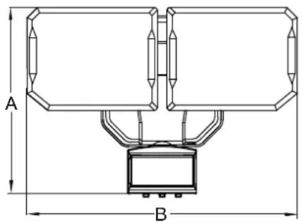
| Dimensions (L x W x D) | 26 x 18 x 11.43 cm (10.25 x 7 x 4.5 in) |
| Power Source | Solar panel + rechargeable lithium-ion 18650 battery (3.7 V, 2000 mAh) or 3 C-type alkaline batteries (1.5 V) |
| Detector Type | Passive Infrared (PIR) Motion Detector |
| Detection Angle | 240° |
| Detection Range | Up to 15.25 m (50 ft) at 25 °C (adjustable: high 15.25 m, medium 9.75 m, low 4.87 m) |
| Color Temperature (bright light) | 5000 K (cool white) |
| Color Temperature (dim light) | 2700 K (warm white) |
| Operation Modes | Off (OFF), Test (Test), Auto (Auto), Energy Saving (ES) |
| Duration Settings | Test: 5 s; Auto: 30 s, 1 min, 2 min; ES: 20 s, 1 min, 2 min |
| Recommended Installation Height | ≥ 2.45 m (8 ft) above ground |
| Warranty | 1 year (manufacturing defects and functionality) |
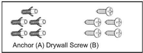
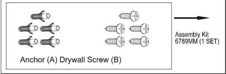
| Package Contents | Light fixture, solar panel, mounting plate, wall anchors (A), drywall screws (B), user manual |
| Maintenance | Clean the detector lens with a soft cloth every 1 to 2 months |
Frequently Asked Questions - Outdoor Security T0722 Vaxcel
User questions about Outdoor Security T0722 Vaxcel
0 question about this device. Answer the ones you know or ask your own.
Ask a new question about this device
Download the instructions for your Lighting in PDF format for free! Find your manual Outdoor Security T0722 - Vaxcel and take your electronic device back in hand. On this page are published all the documents necessary for the use of your device. Outdoor Security T0722 by Vaxcel.
USER MANUAL Outdoor Security T0722 Vaxcel
ASSEMBLY AND INSTALLATION INSTRUCTIONS
T0722
Hardware Package (included):
Important to Know
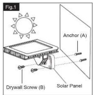
For best results, position the solar panel in a location where it will receive maximum sunlight. Ideally, the location should be free from cover or shade.
Note: Fixture can be wall mounted or eave mounted.
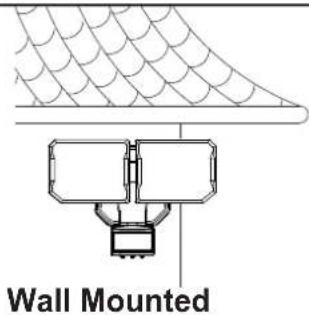
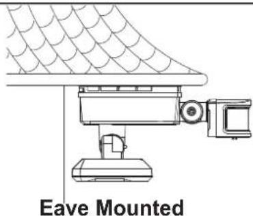
Light fixture and sensor should be mounted as shown above when installed (depending upon type of installation).
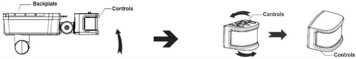
Before installing the light fixture under an eave, the sensor head must be rotated as shown in the next two steps for proper operation and to avoid the risk of electrical shock.
For eave mounted only:
- Swing the sensor head towards the mounting surface.
Rotate the sensor head unclockwise 180° so the controls face down.
flowchart
graph LR
    A["Backplate"] --> B["Control"]
    B --> C["Motor with Controls"]
    C --> D["Control Unit"]
Installation Steps
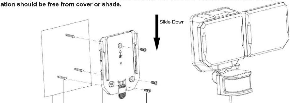
- Slide off mounting plate in back of the light.
- Install the mounting plate to the wall or mounting surface by using drywall screws (B).
If mounting to a wooden surface, drill three 3/32 in. holes into the mounting surface. Install the two mounting screw, through the mounting plate and into the mounting surface.
If mounting to wall board or brick, drill three 7/32 in. holes into the mounting surface. Insert the wall anchors (A) and attach the mounting plate using the three mounting screws.
- Slide the light fixture back onto the mounting plate.
- Place the solar panel to the wall and mark drilling location. Use an electrical drill (not included) to drill two holes into the mounting surface. Then install the solar panel the same way as the mounting plate to the wall using drywall screws (B) with or without anchors (A). (See Fig.1)
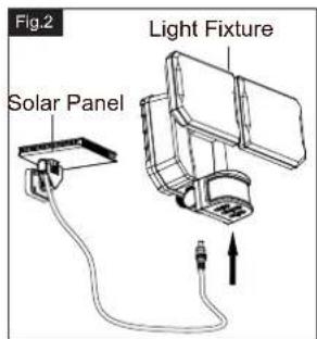
Note: The solar panel is equipped with a 16ft. (5M) connecting wire, so the light fixture and solar panel can be installed up to 16ft. (5M) apart.
- Connect the cable from solar panel to the bottom of light panel to the bottom of light fixture. Only use the included solar panel to charge the light, any other external charger may damage the light fixture. (See Fig.2)
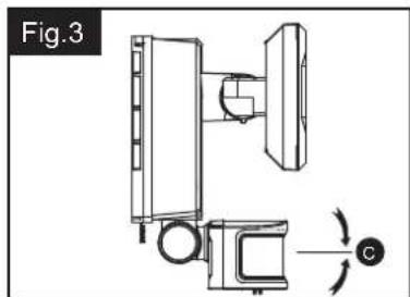
Adjusting the Sensor Head (C):
- Aim sensor head toward desired detection area, maintaining a 5^ - 40^ downward angle to allow moisture to drain. Note: Make sure sensor head is positioned with controls facing toward the ground.
- You can rotate the sensor head up and down to change the coverage area. (See Fig.3)
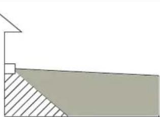
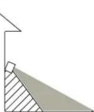
Note: Range set too high may increase false triggering. (See Fig.4 and Fig.5)
natural_image
Technical diagram of a mechanical assembly with labeled components and rotation arrow (no text or symbols)Fig.4
natural_image
Simple geometric diagram showing a vertical line above a shaded triangular region (no text or symbols)Sensor Adjustment Higher For Long Coverage
Fig.5
natural_image
Geometric diagram showing a right triangle with an internal shaded region, no text or symbols presentSensor Adjustment Lower For Short Coverage
Sensitivity of Motion Sensor
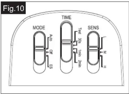
- You can adjust the sensitivity of the motion sensor by using the "SENS" selector located on the right side of the sensor head. (See Fig.10)
- Adjust motion sensor sensitivity to HIGH (H), MEDIUM (M), or LOW (L) to achieve desired performance.
- Approximate range for each setting: 50 ft. (H), 32 ft. (M), 16 ft (L).
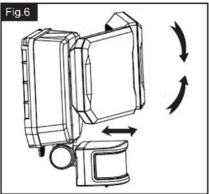
Adjusting the Light Head (B):
- Adjust the light head up or down, left or right for desired area. Keep the light heads at least 1" (25mm) away from the sensor. (See Fig.6)
- Keep the light heads (B) face down around 30 degrees angle to avoid water damage.
natural_image
Diagram of a device with directional arrows indicating rotation or movement (no text or symbols)
VAXCEL
231130
Notes:
- The sensitivity of the motion sensor will increase as the environmental temperature gets cooler. For best performance, gently clean the lens with a soft cloth every 1 or 2 months to ensure maximum sensitivity.
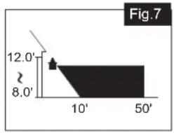
- For best performance, install fixture at least 8 feet above the ground. At such a height, the fixture will provide a detection distance of up to 50 feet at 77 degrees Fahrenheit. (See Fig.7)
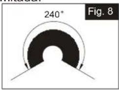
- The sensor detects movement across a detection range of 240 degrees. (See Fig.8)
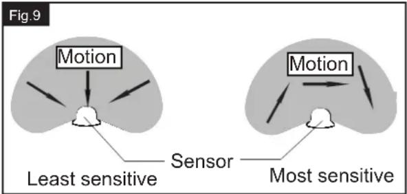
- The sensor will be more sensitive to motion across its detection path than motion directly towards it. (See Fig.9)
- To reduce possible nuisances, do not mount the fixture near a heat source like an air conditioner, vent or furnace.
Where you install your fixture is important:
Be sure the light is mounted straight on the wall;
otherwise, the detection distance may be limited.
area
| X-Axis | Y-Axis | |---|---| | 0 | 12.0' | | 10' | 8.0' | | 50' | 8.0' |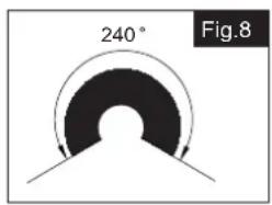
Functions and operations:
Choose a mode by sliding the switch on the bottom of the sensor of the fixture. (See Fig.10)
1. OFF MODE
- The fixture will have the mode switch be set at "OFF" as default.
- In "OFF" MODE, the power is turned off to save power and improve battery charging.
2. TEST MODE (daytime and nighttime operation.)
- Slide the "TIME" switch on the sensor head to the "Test" position.
Slide the "MODE" switch to "Auto" or "ES" position to operate test mode. - The light turns to high-level brightness (5000K) when motion is detected, and stays on as long as there's motion being detected. After there's no further motion being detected for 5 seconds, it will revert back to low-level brightness (2700K), and then turns off automatically after another 5 seconds if no further motion is detected.
3. AUTO MODE (nighttime operation only)
In “AUTO” mode, slide the “Time” switch to the desired time setting (30s/1min/2min). At dusk, the light turns on to low-level brightness (2700K). When motion is detected, the light turns to high-level brightness (5000K) and stays on as long as there’s motion being detected. After there’s no further motion being detected, the high-level brightness (5000K) will remain on for the predetermined time you set (30s/1min/2min), and then switches back to low-level brightness (2700K) automatically if no further motion is detected.
The light will turns off automatically at dawn.
4. Energy Saving MODE (nighttime operation only)
In “ES” mode, slide the “Time” switch to the desired time setting (20s/1min/2min). At dusk, the light stays off. When motion is detected, the light turns to high-level brightness (5000K) and stays on as long as there’s motion being detected. After there’s no further motion being detected for the first 10 seconds, the high-level brightness (5000K) will reduce to low-level brightness (2700K) for the remaining predetermined time you set (30s/1min/2min), and then turns off automatically if no further motion is detected.
The light will turns off automatically at dawn.
2 TYPES OF POWER METHODS
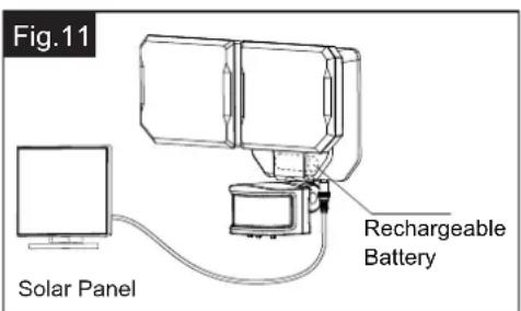
A. Operate by Solar Power: (See Fig.11)
Power by rechargeable battery inside the battery compartment. This rechargeable battery can be charged by the solar panel. (See Fig.11)
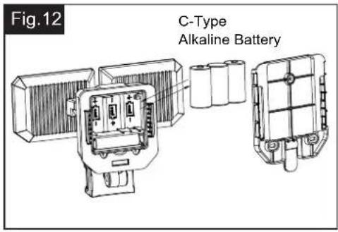
B. Operate by Battery Power: (Fig.12)
Powered by using 3pcs 1.5V C-Type Alkaline Batteries (Batteries not included). (See Fig.12)
Notes:
To maximizing the operation time, it is recommended to purchase and install 3pcs C-Type Alkaline Batteries.
TO INSERT / CHANGE BATTERIES
Using the Alkaline Batteries and Replacing the Rechargeable Battery
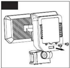
- Unscrew two screws at the back of the light fixture to unlock the compartment and pull the cover open. (See Fig.13)
natural_image
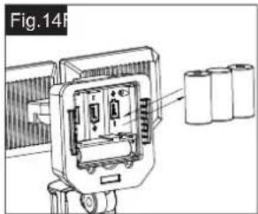
Technical line drawing of a mechanical device with no visible text or symbols- Insert the Alkaline batteries or replace the rechargeable battery then close the plate. (See Fig.14)
Note: Using Alkaline Dry Batteries (C-Type 1.5V x 3).
Uses 1pc of 18650
3.7V 2000mah Lithium ion Battery.
- Tighten the two screws at the back of the light fixture to secure the compartment. (See Fig.15)

natural_image
Technical line drawing of a mechanical device with no visible text or symbols- Three typical alkaline C-batteries will last 10 hours within this fixture (36,000 seconds).
Estimate that the batteries will last between 75 and 450 days using the assumptions below:
450 days = 10-second light duration at 8 "light on" intervals per day (36,000 seconds / 80 seconds per day = 450 days)
75 days = 60-second light duration at 8 "light on" intervals per day (36,000 seconds / 480 seconds per day = 75 days)
The following parts are available for reorder if damaged or missing.
Spare Parts List:
TROUBLESHOOTING
If the light does not turn on: Ensure solar panel is positioned to receive direct sunlight and is not blocked by trees or other objects. Remove the battery, wipe both ends with a clean, dry cloth and reinstall the battery. Check the battery to ensure that it is making secure contact with the terminals. If this does not work, replace with a new battery.
natural_image
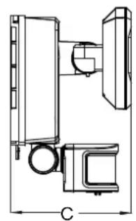
Technical line drawing of a mechanical assembly with labeled dimension C (no text or symbols present)A: 7"
B: 10-1/4"
C: 4-1/2"
1 Year Warranty
Vaxcel warrants all of our products against defects in workmanship and finishes for one year following the date of shipment.
Additionally, all solar powered lighting is supported by a one year warranty for the functionality of the product.
Exclusions: This warranty does not include the failure of products from extreme acts of nature; environmental conditions not suited for the products intended use; operation in temperatures outside of the range specified in the instruction manual; usage with improper power supply, power surges or dips. For coastal locations, some corrosion is considered normal for the environment.
Vaxcel reserves the right to repair, replace or issue a credit for any properly installed product, provided it is returned per RMA instruction. This warranty is limited to the cost of the product only and does not extend to transportation, installation or replacement costs.
How can warranty service be obtained?
info@vaxcel.com
1-800-482-9235
Ajuste del cabezal sensor (C):
natural_image
Simple geometric diagram showing a right angle with a shaded triangular region and a vertical line (no text or symbols)natural_image
Technical line drawing of a mechanical assembly with no visible text or symbolsnatural_image
Diagram of a device with directional arrows indicating rotation or movement (no text or symbols)
VAXCEL
Notas:

natural_image
Technical line drawing of a mechanical device with no visible text or symbolsnatural_image
Technical line drawing of a mechanical device with no visible text or symbolsnatural_image
Technical line drawing of a mechanical assembly with labeled dimension C (no text or symbols present)A: 7 pulgadas
B: 10-1/4 pulgadas
C: 4-1/2 pulgadas
Garantía de 1 año
natural_image
Technical diagram of a mechanical assembly with labeled components and rotation arrow (no text or symbols)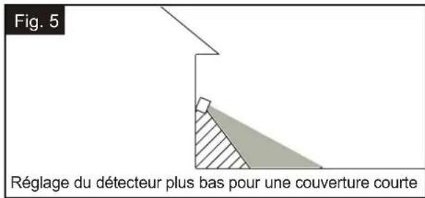
natural_image
Line drawing of a device with directional arrows indicating rotation or cycle (no text or symbols)Remarques :
natural_image
Technical line drawing of a mechanical device with no visible text or symbolsnatural_image
Technical line drawing of a mechanical component with battery pack and housing (no text or symbols)natural_image
Technical line drawing of a mechanical device with a meshed base and cylindrical component (no text or symbols)- ASSEMBLY AND INSTALLATION INSTRUCTIONS
- Installation Steps
- Adjusting the Sensor Head (C):
- Sensitivity of Motion Sensor
- Adjusting the Light Head (B):
- Notes:
- Functions and operations:
- OFF MODE
- TEST MODE (daytime and nighttime operation.)
- AUTO MODE (nighttime operation only)
- Energy Saving MODE (nighttime operation only)
- TYPES OF POWER METHODS
- Operate by Solar Power: (See Fig.11)
- TO INSERT / CHANGE BATTERIES
- Using the Alkaline Batteries and Replacing the Rechargeable Battery
- TROUBLESHOOTING
- Year Warranty
- Ajuste del cabezal sensor (C):
- Notas:
- Garantía de 1 año
- Remarques :
Brand : Vaxcel
Model : Outdoor Security T0722
Category : Lighting