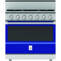
KRG365 - Cooker Hestan - Free user manual and instructions
Find the device manual for free KRG365 Hestan in PDF.


| Product type | Gas range |
| Brand | Hestan |
| Model | KRG365 |
| Width | 36 in (91.4 cm) |
| Height (adjustable) | 36.875 - 38.375 in (93.7 - 97.5 cm) |
| Total depth | 48.3125 in (122.7 cm) |
| Weight (estimated) | Approximately 113 kg (250 lb) |
| Power supply | 120 V, 60 Hz, single-phase, 15 A, dedicated circuit |
| Gas type | Natural gas or propane (convertible) |
| Number of burners | 5 burners (including sealed dual-flame and single-flame burners) |
| Surface material | Stainless steel |
| Oven - cooking modes | Bake and Broil |
| Oven - lighting | Interior light with switch |
| Ignition | Electric (spark) |
| Safety - Anti-tilt device | Included, must be installed |
| Safety - Gas shut-off | Manual shut-off valve recommended upstream |
| Backsplash | Profiled backsplash for island supplied as standard; low backsplash or high shelf available as option |
| Leveling feet | 4 adjustable feet |
| Included accessories | Cooking grates and burner caps |
| Spare parts | Contact Hestan customer service |
| Repairability | Repairs by qualified technician only |
Frequently Asked Questions - KRG365 Hestan
User questions about KRG365 Hestan
0 question about this device. Answer the ones you know or ask your own.
Ask a new question about this device
Download the instructions for your Cooker in PDF format for free! Find your manual KRG365 - Hestan and take your electronic device back in hand. On this page are published all the documents necessary for the use of your device. KRG365 by Hestan.
USER MANUAL KRG365 Hestan
natural_image
Close-up of a cooked dish featuring various vegetables and root vegetables with herbs (no text or symbols visible)INDOOR COOKING
All-Gas Range
KRG
Installation Manual
WARNING
IF THE INFORMATION IN THIS MANUAL IS NOT FOLLOWED EXACTLY, A FIRE OR EXPLOSION MAY RESULT CAUSING PROPERTY DAMAGE, PERSONAL INJURY, OR DEATH.
Do not store or use gasoline or other flammable vapors and liquids in the vicinity of this or any other appliance.
WHAT TO DO IF YOU SMELL GAS:
- Do not try and light any appliance.
- Do not touch any electrical switch.
- Do not use any phone in your building.
- Immediately call your gas supplier from a neighbor's phone. Follow the gas supplier's instructions.
- If you cannot reach your gas supplier, call the fire department.
Installation and service must be performed by a qualified installer, service agency, or the gas supplier.
READ THESE INSTRUCTIONS CAREFULLY AND COMPLETELY BEFORE INSTALLING OR USING YOUR APPLIANCE TO REDUCE THE RISK OF FIRE, BURN HAZARD, OR OTHER INJURY. KEEP THIS MANUAL FOR FUTURE REFERENCE.
SAFETY DEFINITIONS

THIS INDICATES THAT DEATH OR SERIOUS INJURY MAY OCCUR AS A RESULT OF NOT OBSERVING THIS WARNING.

THIS INDICATES THAT MINOR OR MODERATE INJURY MAY OCCUR AS A RESULT OF NOT OBSERVING THIS WARNING.

THIS INDICATES THAT DAMAGE TO THE APPLIANCE OR PROPERTY MAY OCCUR AS A RESULT OF NOT OBSERVING THIS WARNING.
INSTALLER: LEAVE THIS MANUAL WITH THE OWNER OF THE APPLIANCE. HOMEOWNER: RETAIN THIS MANUAL FOR FUTURE REFERENCE.
WARNING
TIP OVER HAZARD
A child or adult can tip over a range and be killed.
Check installation of the anti-tip device per the Installation Manual. Do not operate the range without this device in place.

natural_image
Silhouette of a person pushing a large block on a horizontal line (no text or symbols)Check engagement of anti-tip device if range is moved, such as when cleaning behind the unit.
To check engagement, carefully tip the range forward while pulling from the rear of the unit. The range should not move more than 1 inch [2.5cm].
Failure to follow these instructions can result in death or serious burns to children and adults.
To reduce the risk of burns, do not move this appliance while hot.
TABLE OF CONTENTS
1 SAFETY PRECAUTIONS - BEFORE YOU BEGIN
2 MODEL NUMBERS
3 RATING LABEL
3 REGULATORY / CODE REQUIREMENTS
3 LOCATION AND INSTALLATION / VENTILATION
10 BACKGUARD AND ACCESSORIES
10 INSTALLATION OF ANTI-TIP DEVICE
12 ELECTRICAL CONNECTIONS
13 GAS CONNECTION
15 FINAL SETUP
16 SERVICE
17 APPENDIX
SAFETY PRECAUTIONS - BEFORE YOU BEGIN
When properly cared for, your Hestan appliance will provide safe, reliable service for many years. When using this appliance, basic safety practices must be followed as outlined below.
IMPORTANT: Save these instructions for the local Gas or Utility Inspector's use.
INSTALLER: Please leave these Installation Instructions with the owner.
OWNER: Please retain these Installation Instructions for future reference.
This range is NOT designed for installation in manufactured (mobile) homes or recreational park trailers. Do NOT install this range outdoors.
WARNING
ELECTRICAL SHOCK HAZARD
Disconnect power before installing or servicing appliance. Before turning power ON, be sure all controls are in the OFF position. Failure to do so can result in electrical shock or death.
ELECTRICAL GROUNDING
This appliance must be grounded. Grounding reduces the risk of electric shock in the event of a short circuit. Read the ELECTRICAL CONNECTIONS section of this manual for complete instructions.
natural_image
Silhouette of a person in motion, possibly shooting or arching, with no visible text or symbolsThis appliance is equipped with a 3-prong grounding plug for your protection against shock hazard and should be directly plugged into a properly grounded receptacle. Do not cut or remove the grounding prong from this plug.
ELECTRICAL SUPPLY
The appliance must be on its own dedicated circuit - 120 VAC, Single Phase, 60 Hz, with a current rating as shown in the model number listing on pg. 2. Have the installer show you where the electric circuit breaker is located so you know how to shut off the power to this appliance. It is the responsibility of the user to have the appliance connected by a licensed electrician in accordance with all local codes, or in the absence of local codes, in accordance with the National Electrical Code. Read the ELECTRICAL CONNECTIONS section of this manual for complete details.
RANGE MODELS
| MODEL NO. | DESCRIPTION | DESCRIPTION | CIRCUIT BREAKER REQUIRED |
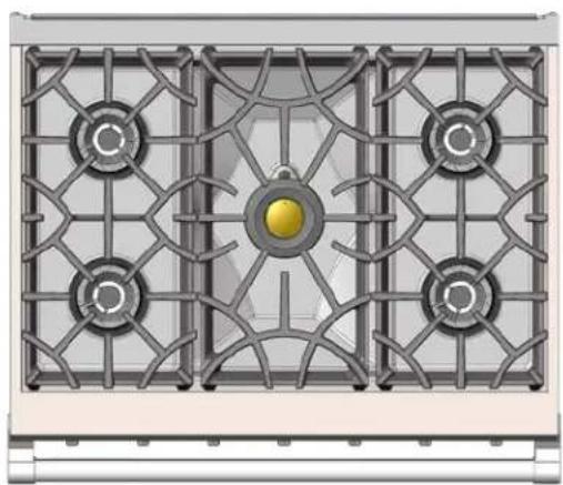
| KRG365-NG / -LP 36" | GAS RANGE WITH 5 BURNERS 15 Amp | ||
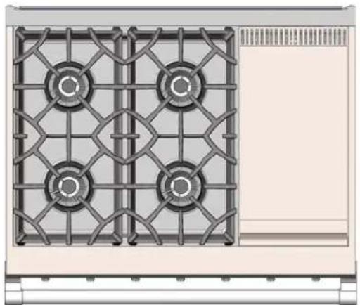
| KRG364GD-NG / -LP 36" | GAS RANGE WITH 4 BURNERS & GRIDDLE 15 Amp |
natural_image
Top-down view of a grid-patterned industrial or electrical cabinet with four circular components and a central yellow knob (no text or symbols)KRG365 KRG364GD
natural_image
Top-down architectural rendering of a four-gate kitchen stove with lattice windows and a side panel (no text or symbols)KRG364CD
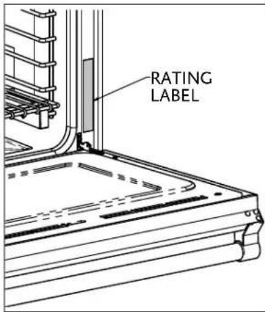
RATING LABEL
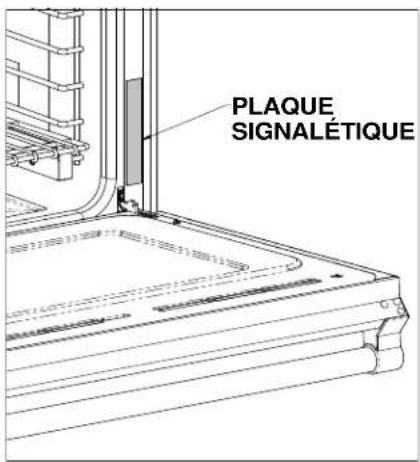
The rating label contains important information about your Hestan appliance such as the model and serial number, gas type and manifold pressure, electrical rating, the BTU rating for each burner type, and the minimum installation clearances.
The rating label is located on the right side of the oven cavity opening near the door hinge.
If service is necessary, contact Hestan Customer Care with the model and serial number information shown on the label.
| HSTAN COMMERCIAL CORP. ANAHAMI CA. USA | MODEL / MODELE | SER. NO./NO.SER. | FUTATED: http://www.hestancomercip.com/ | |||||||
| VOLTS | BURNER RINGS (ST/HOUSE) | MIN CLENARLES / DESGMENTS | COMMENTS TO AVE 0752-21-1301, 024-11-2016 HOUSEHOLD DOCKING GAS APPLICATION CONFORME ALAUXONE AND MAXI 211-2016, CN 11-2016 APPROVAL ELECTRONOMETER 35 COCONDER GAS VENTED: KEY INSTALLATION MANUAL UNITS (VENTIL): KEY MANSI (EXPANSIONAL) | |||||||
| Hz | 60 | TORT FUNDS BREAD | HEAT BURGER BREAD/AMOUNT | GREEN PLUGS CHAPES | LIFE/BURGER (FULL POUNDERS) | OVERBURNER (FULL POUNDERS) | TOTAL ASSETS | COMMENTS | NO COMMENTS | |
| PHASE | 1 | INCH N.C. | 12" | 0" | UNITED BY: KELINDA INC. | |||||
| AMPS | IPM | 12" | 0" | UNITED BY: KELINDA INC. | ||||||
REGULATORY/CODE REQUIREMENTS
Installation of this cooking appliance must be made in accordance with local codes. In the absence of local codes, this unit should be installed in accordance with the National Fuel Gas Code ANSI Z223.1/NFPA 54, Natural Gas and Propane Installation code CSA B149.1, or Propane Storage and Handling Code B149.2.
All Electrical Components must be electrically grounded in accordance with local codes or in the absence of local codes with the National Electrical Code ANSI/NFPA 70, or Canadian Electrical code CSA C22.1.
STATE OF MASSACHUSETTS
Massachusetts requires all gas be installed using a plumber or gas fitter carrying the appropriate Massachusetts license. All permanently installed natural gas or propane installations require a T handle type manual gas valve be installed in the gas supply line to this appliance. Flexible gas connector must not be longer than 48" [1.2 m].
CALIFORNIA PROPOSITION 65 - WARNING

WARNING This product can expose you to chemicals including carbon monoxide, which is known to the State of California to cause birth defects or other reproductive harm. For more information, go to www.P65Warnings.ca.gov.
LOCATION AND INSTALLATION / VENTILATION
UNPACKING AND PLACEMENT
Remove the outer carton and packing materials from the shipping pallet. Do not remove the plastic film covering the stainless-steel surfaces. This film protects the finish from scratches until the appliance is installed in its final position.
The unit is very heavy and should be handled with care. Use proper safety equipment, such as gloves, and at least 2 persons to move the appliance into position to avoid injury and to avoid damage to the floor or the appliance itself.

DO NOT USE A HAND TRUCK OR DOLLY ON THE FRONT OR REAR OF THE RANGE. HANDLE AND MOVE FROM THE SIDES ONLY.
Do not lift or carry the appliance by the oven door or handle. This could damage the door hinges.
LOCATION AND INSTALLATION / VENTILATION(CONTINUED)
The range is held onto the pallet with 4 large shipping bolts on both sides. Remove these bolts and then move the range to the floor with the help of 2 persons.
PREPARATION
Before moving the range, protect any finished flooring and secure the oven door(s) closed to prevent damage.
GAS AND ELECTRICAL SUPPLY CLEARANCES
If not already in place, install a gas shut-off valve in an easily accessible location for servicing of the range. Make sure all users of the range know where this shut-off is located, and how to shut off the gas. Any openings in the wall or floor behind the appliance must be sealed. The Installation Clearances on the following pages show where the "G" and "E" zones should be located.
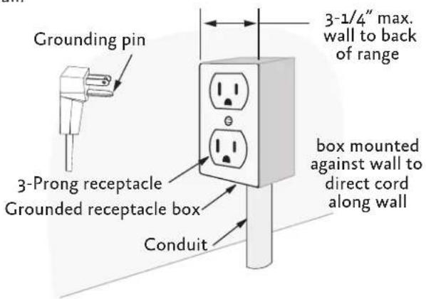
The range is designed to be installed nearly flush to the rear wall*. It may be necessary to reposition the gas supply and power receptacle / junction box in order to accommodate the range when pushed back against the wall.
The back of the range is recessed 3-1/4" [8.3 cm] to provide room for the cord and gas pipe. If using a wall-mounted junction box/outlet, it may need to be mounted to direct the cord along the wall instead of toward the range.

* Unless installed in an island with no rear wall.
CABINETRY
To eliminate the risk of burns or fire by reaching over heated surface units, cabinet storage space located above the surface units should be avoided. If cabinet storage is to be provided, the risk can be reduced by installing the required vent hood that projects horizontally a minimum of 5" [12.7 cm] beyond the bottom of the cabinets.
LOCATION AND INSTALLATION/VENTILATION (CONTINUED)
OVEN DOOR REMOVAL
If you have a very narrow door opening to your kitchen, the oven door(s) can be removed. REMOVE ONLY IF ABSOLUTELY NECESSARY. Door removal should only be done by a certified installer or service technician. Be sure the oven has completely cooled and the electrical power is off. Failure to do so may result in electric shock or burn injury. Use caution when removing the door, it is very heavy.
- Open oven door completely.
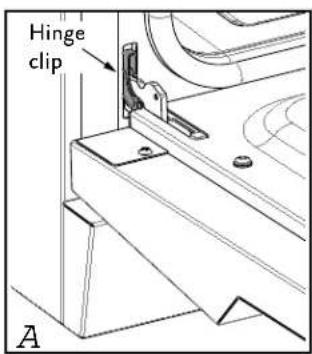
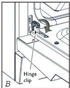
- At each hinge location, swing the hinge clip forward until it stops. A screwdriver may be needed to do this. [B]
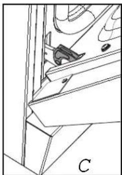
- Gently close the oven door until it stops against the hinge clips, or approximately 30^ from the closed position. Hold on firmly to both sides of the door (not the handle) and pull the door straight up off the hinges. Place the oven door in a safe location until needed. NEVER release the hinge clips and try to close the hinges. Doing so will snap the hinges closed with great force which could cause injury. [C & D]
natural_image
Technical line drawing of a mechanical component with no visible text or symbols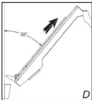
RE-INSTALL OVEN DOOR
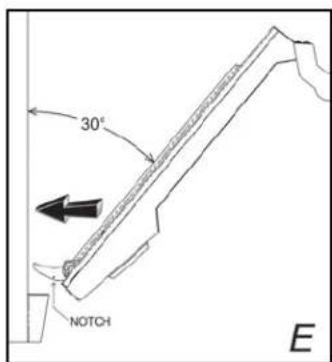
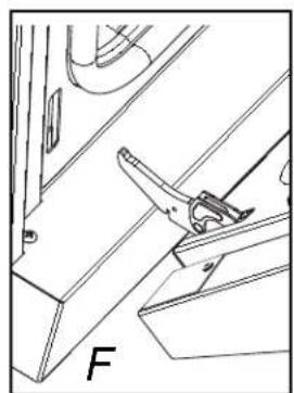
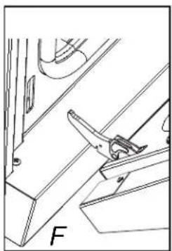
- Hold the door firmly on both sides (NOT FROM THE HANDLE) at approximately 30^ from the closed position and insert the hinges into the slots in the oven. The bottom edge of each hinge has a notch which must seat inside the slot opening. DO NOT FORCE OR BEND OR TWIST THE DOOR! [E & F]
- Slowly open the door all the way. Swing the hinge clips away from you until completely inside the slot opening and fully seated. A screwdriver may help you do this. [G]
- Gently close the oven door to check for smooth operation.
natural_image
Technical line drawing of a mechanical assembly with labeled component 'F' (no text or symbols beyond label)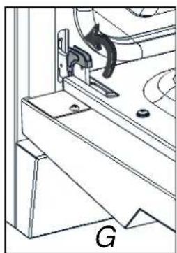
natural_image
Technical line drawing of a mechanical assembly with no visible text or symbols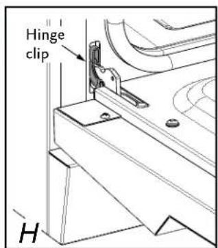
LOCATION AND INSTALLATION/VENTILATION(CONTINUED)
LEVELING
The range must be level, especially those models featuring a griddle. Raise or lower the range to the desired height by adjusting the four leveling legs under the range. The legs can be turned by hand. It may be necessary to use a lever or other lifting device to assist in temporarily raising the unit to turn the legs. Do not lift or lever from the front or back, only from the sides.
The appliance top must be level or higher than the adjacent countertop surfaces. Failure to adjust the height may expose the adjacent cabinets to excessive heat which may damage the cabinets or countertop.

INSTALLATION CLEARANCES WITH LOW BACKGUARD
![COMBUSTIBLE MATERIALS APPLIANCE TOP COOKING SURFACE REF 1.12" [2.84 cm] HANDLE END CAP 7" [17.7] 38-3/8 - 36-7/8" [97.5 - 93.7] TO COOKING SURFACE 2-5/8" [6.7] 30-13/16" [78.3] 24-11/16" [62.7] MAX. RECESS DEPTH FINISHED FLOOR 48-5/16" [122.7] 3" [7.6] DIMENSIONS IN BRACKETS [ ] ARE IN CM. LOCATION OF GAS AND ELECTRICAL ON FLOOR.](/content/2026/04/741818/images/814b41ad18622792185d6bcd29ad0855e741b06e90ba49b66efb6d0eb057e8a9.jpg)
SIDE VIEW
LOCATION AND INSTALLATION/VENTILATION(CONTINUED)
INSTALLATION CLEARANCES 36" WITH LOW BACKGUARD
![COMBUSTIBLE MATERIALS VENT HOOD 18" [45.7] MIN. V W MIN. CLEARANCE TO NEAREST COMBUSTIBLE SIDE SURFACE 12" [30.5] COUNTERTOP FULL OVERLAY DRAWER FACE 1/8" [3.2 mm] FULL OVERLAY CABINET DOOR FACE DIMENSIONS IN BRACKETS [] ARE IN CM. G E 11" [28] 11" [28] 18" [45.7] 3" [7.6] ELECTRICAL SUPPLY LOCATION 6" [15.2] 2-1/2" [6.4] 5" [12.7] FINISHED FLOOR RECOMMENDED GAS SHUT-OFF VALVE LOCATION FRONT VIEW](/content/2026/04/741818/images/7b456c7aae8f2ba773dfa649464f40f8ceea881e852b542d5916902986663b29.jpg)
| RANGE MODEL | W V (MIN) |
| KRG365 36" [91.4] 30" [76.2] | |
| KRG364GD 36" [91.4] 30" [76.2] |
NOTES:
• SHADED AREAS INDICATE WHERE COMBUSTIBLE MATERIALS ARE NOT ALLOWED.
• APPLIANCE TOP MUST BE LEVEL OR HIGHER THAN THE ADJACENT COUNTERTOP SURFACES.
- "G" IS GAS CONNECTION ZONE ON REAR WALL. MOUNT SHUT-OFF VALVE AS HIGH AS POSSIBLE IN THIS ZONE FOR EASY ACCESS WHEN RANGE IS INSTALLED.
• "E" IS ELECTRICAL SUPPLY ZONE.
- "W" IS APPLIANCE OPENING.
NOTE: HANDLE END CAPS PROTRUDE 1/8" BEYOND EACH SIDE OF THE RANGE. ALLOWANCE MAY BE NEEDED FOR ADJACENT DRAWERS OR CABINETRY.
• "V" IS MIN. CLEARANCE TO REQUIRED VENTILATION HOOD.
INSTALLATION CLEARANCES WITH ISLAND TRIM
![COMBUSTIBLE MATERIALS MIN. CLEARANCE TO COMBUSTIBLE SURFACES WITH ISLAND TRIM 12" [30.5] FOR ISLAND TRIM installations, counter surface should have a cantilever surface meeting the rear of the Island Trim ISLAND TRIM HANDLE END CAP 7" [17.7] 38-3/8 - 36-7/8" [97.5 - 93.7] TO COOKING SURFACE 2-5/8" [6.7] 30-13/16" [78.3] 24-11/16" [62.7] MAX. RECESS DEPTH FINISHED FLOOR 48-5/16" [122.7] 3" [7.6] DIMENSIONS IN BRACKETS [ ] ARE IN CM. LOCATION OF GAS AND ELECTRICAL ON FLOOR](/content/2026/04/741818/images/680f4f3e43ed8598481333991c453cd5f986cfadbf75078bfc8a468c9e918415.jpg)
SIDE VIEW
VENTILATION REQUIREMENTS
It is strongly recommended that this appliance be installed with a Hestan vent hood. Due to the high heat output of this range, it is very important that the hood and ductwork installation meets local building codes and is installed by a qualified technician.
Do not use a down-draft style ventilation system.
Do not mount a microwave oven/ventilator combination above the range. These type of units do not have sufficient airflow to remove the high heat output of this range and were not tested with this type of appliance.
For non-Hestan approved vent hoods, the vent hood and/or blower unit must be rated for 1 CFM [1.7 m³/hr] for every 100 BTU [.03 kW]. (See rating plate for BTU rating of your unit.)
- If the range has a 12" Griddle, add an additional 200 CFM [340 m ^3 /hr] to the blower capacity.
LOCATION AND INSTALLATION/VENTILATION(CONTINUED)
INSTALLATION CLEARANCES 36" WITH ISLAND TRIM
![COMBUSTIBLE MATERIALS 12" [30.5] MIN. CLEARANCE TO NEAREST COMBUSTIBLE SIDE SURFACE COUNTERTOP FULL OVERLAY DRAWER FACE 1/8" [3.2 mm] FULL OVERLAY CABINET DOOR FACE DIMENSIONS IN BRACKETS [ ] ARE IN CM. RECOMMENDED GAS SHUT-OFF VALVE LOCATION ELECTRICAL SUPPLY LOCATION 6" [15.2] 2-1/2" [6.4] 5" [15.2] FINISHED FLOOR V W G E 11" [28] 11" [28] 18" [45.7] 3" [7.6]](/content/2026/04/741818/images/b503ab1777ee3f6bf611ccd5e8a44b2a2387085056c300af3ad6d4ca2dce340b.jpg)
FRONT VIEW
| RANGE MODEL | W V (MIN) |
| KRG365 36" [91.4] 30" [76.2] | |
| KRG364GD 36" [91.4] 30" [76.2] |
NOTES:
• SHADED AREAS INDICATE WHERE COMBUSTIBLE MATERIALS ARE NOT ALLOWED.
• APPLIANCE TOP MUST BE LEVEL OR HIGHER THAN THE ADJACENT COUNTERTOP SURFACES.
- "G" IS GAS CONNECTION ZONE ON REAR WALL. MOUNT SHUT-OFF VALVE AS HIGH AS POSSIBLE IN THIS ZONE FOR EASY ACCESS WHEN RANGE IS INSTALLED.
• "E" IS ELECTRICAL SUPPLY ZONE.
- "W" IS APPLIANCE OPENING.
NOTE: HANDLE END CAPS PROTRUDE 1/8" BEYOND EACH SIDE OF THE RANGE. ALLOWANCE MAY BE NEEDED FOR ADJACENT DRAWERS OR CABINETRY.
• "V" IS MIN. CLEARANCE TO REQUIRED VENTILATION HOOD.
LOCATION AND INSTALLATION/VENTILATION(CONTINUED)
For island applications, it is recommended to use a vent hood that is 6" [15.2 cm] wider than the appliance, to allow for 3" [7.6 cm] of overlap on the left and right of the appliance.
Keep duct runs as short and straight as possible. Elbows and transition fittings reduce airflow efficiency. Hestan recommends keeping the duct run under 50 ft. [15.2 m].
Consult with your Hestan dealer on selecting the appropriate vent hood for your Hestan appliance.
BACKGUARD AND ACCESSORIES
CAUTION
Sheetmetal accessories such as the backguard, and areas at the rear of the range may have sharp edges. Wear work gloves while handling and installing these items.
BACKGUARD
Your Hestan range is supplied at the factory with an Island Trim backguard. See Table 1 in the APPENDIX section of this manual for other backguard options available from your Hestan dealer. Selection of the appropriate backguard depends on the installation location and adjacent materials, and the type of vent hood to be used. Installation instructions are included with the backguard kit. A LOW OR TALL BACKGUARD IS REQUIRED WHEN INSTALLING THE RANGE AGAINST A COMBUSTIBLE SURFACE - THE ISLAND TRIM IS NOT SUITABLE.
CAUTION
The top of the backguard serves as an exhaust for the oven when in operation, and as an exhaust vent to remove heat from under the cooktop section of the range as well.
- DO NOT BLOCK or obstruct the top of the backguard.
- DO NOT touch the top of the backguard during appliance operation as it may get hot. Allow sufficient time to cool before touching or cleaning this area.
- DO NOT position plastic or other heat-sensitive items nearby which could melt or burn.
INSTALLATION OF ANTI-TIP DEVICE
WARNING
THE ANTI-TIP DEVICE PROVIDED WITH THIS RANGE MUST BE INSTALLED.
PREPARATION
NOTICE
POSSIBLE PROPERTY DAMAGE - Use a qualified installer or contractor to determine the proper method of attaching the anti-tip bracket to the rear wall or
floor behind your range. Special drills or tools may be needed to drill holes in the wall or floor (ceramic tile, hardwood flooring, etc.).
WARNING
ELECTRICAL SHOCK HAZARD - Use extreme caution when drilling holes into the wall or floor as there may be hidden wires. Identify the electrical
circuits that could be affected by the installation of the anti-tip bracket. Shut off the power to these circuits. Failure to follow these instructions may result in death or electrical shock.
HOLE PREPARATION
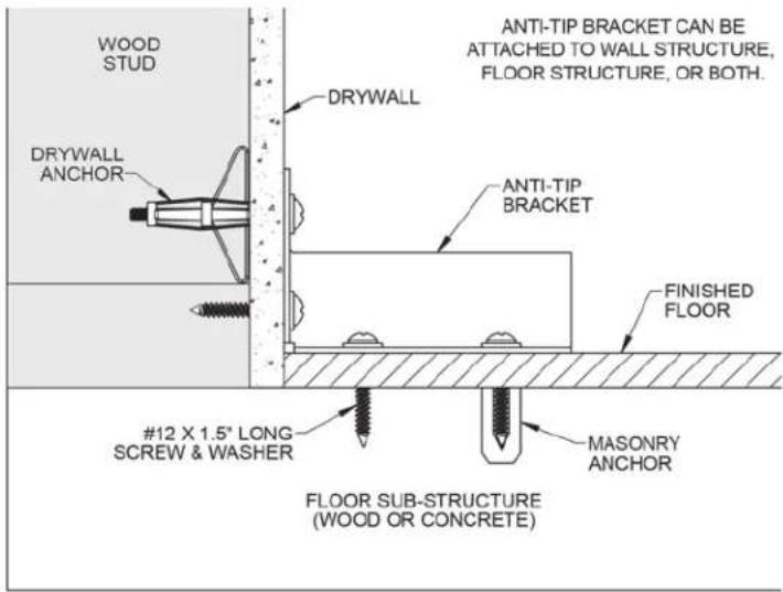
The anti-tip bracket must be installed in sound materials, such as wood studs in the wall AND floor joists under the finished floor. They must be able to withstand the forces exerted on the bracket by the range should it tip-over. If wood studs or other suitable materials are not in the designated area behind the range, you must attach the bracket using appropriate drywall anchors or similar fasteners.
INSTALLATION OF ANTI-TIP DEVICE (CONTINUED)
DRYWALL INSTALLATION: After positioning the bracket as per the diagram below, mark the holes and drill the appropriate holes as per the instructions supplied with the wall anchors. For hardboard or solid plaster walls, you may need different wall anchors, available at your local hardware store or home center.
WOOD FLOOR INSTALLATION: After positioning the bracket as per the diagram below, mark the holes and drill the appropriate holes for #12 or similar, large wood screws, at least 1.5" [3.8 cm] in length. Use washers as well. All hardware is available at your local hardware store or home center.
CONCRETE FLOOR INSTALLATION: After positioning the bracket as per the diagram below, mark the holes and drill the appropriate holes for #12 or similar large masonry anchors, at least 1.5" [3.8 cm] in length. Use washers as well. All hardware is available at your local hardware store or home center.
![WOOD STUD INSIDE WALL 1-1/8" [3] FLOOR CABINET](/content/2026/04/741818/images/fc0d7a4d98af8c7a86f800f2cd8c01d1ce518710fa8c0f78ae796f5dacceaef8.jpg)
ANTI-TIP BOLT ADJUSTMENT
After leveling the range, and after the bracket has been attached, adjust the anti-tip bolt and large washer under the range so the top of the washer is 1-1/4" [3.2 cm] maximum from the floor. Slide the range into the opening of the bracket and verify the bolt is engaged in the bracket as seen below. Carefully tip the range forward to check. The range should not move more than 1" [2.5 cm].
![1-1/4" [3.2] ANTI-TIP BOLT & WASHER ANTI-TIP BRACKET](/content/2026/04/741818/images/d06611fb33bf6a2226806b7b2be124104b16e39f4c7883f74be75ea7fab3cc8d.jpg)
REAR VIEW
WARNING
ELECTRICAL SHOCK HAZARD
Disconnect power before installing or servicing appliance. Before turning power ON, be sure all controls are in the OFF position. Failure to do so can result in electrical shock or death.
ELECTRICAL GROUNDING
This appliance must be grounded. Grounding reduces the risk of electric shock in the event of a short circuit. Grounding through the neutral conductor is prohibited for new branch circuit installations (1996 NEC), mobile homes, and recreational vehicles, or in an area where local codes prohibit it. Your Hestan range is equipped with a 3-prong, grounding type plug which must be plugged into a grounded, 3-prong 120V receptacle.
natural_image
Silhouette of a person in motion with a curved arrow, no text or symbols presentCAUTION
Improper grounding will cause malfunctions in the unit, such as continuous sparking of the igniters. This can damage the appliance and create a shock hazard condition.
ELECTRICAL CONNECTION
The receptacle must be on its own dedicated circuit - 120 VAC, Single Phase, 60 Hz, with a current rating of 15 Amps. If this is not available, a licensed electrician must install the appropriately dedicated and grounded receptacle. The installation must be done in accordance with local codes, or in the absence of local codes, it must be installed in accordance with the National Electrical Code, ANSI/NFPA 70.
- Make sure power is off at the supply panel / breaker.
- Plug the appliance into the wall receptacle. Secure extra appliance cord out of the way so it cannot be snagged or pinched behind your range.
- Before restoring power at the supply panel / breaker, be sure all controls are in the OFF position.
GAS SUPPLY
The local gas authority or supplier should be consulted at the installation planning stage in order to establish the availability of an adequate supply of gas (NG or LP). If it is a new installation, have the gas authorities or supplier check the meter size and piping to assure that the unit is supplied with the necessary amount of gas supply and pressure to operate the unit(s).
Gas connections should be made by a qualified plumber, or your professional appliance installer.
All appliances must be fitted with an accessible upstream gas shutoff valve as a means of isolating the appliance for emergency shut off and for servicing.
Make certain new piping and connections have been made in a clean manner and have been purged so that piping compound, chips, etc. will not clog regulators, valves, orifices, or burners. Use pipe joint compound / thread sealant approved for natural and LP gases.
The appliance and its individual manual shutoff valve must be disconnected from the gas supply piping system during any pressure testing of that system at test pressures in excess of 1/2 psi [3.5 kPa].
The appliance must be isolated from the gas supply piping system by closing its individual manual shutoff valve during any pressure testing of that system at test pressures equal to or less than 1/2 psi [3.5 kPa].
NEVER CONNECT THE APPLIANCE TO AN UNREGULATED GAS SUPPLY. Before proceeding, ensure the appliance is fitted for Natural or Liquid Propane gas. Connecting to an improper gas type will result in poor performance and increased risk of damage or injury. Gas type and gas consumption (BTU per hour) for each burner type is shown on the rating label.
Installation of this cooking appliance must be made in accordance with local codes. In the absence of local codes, this unit should be installed in accordance with the National Fuel Gas Code No. Z223.1/NFPA 54, Natural Gas and Propane Installation code CSA B149-1, or Propane Storage and Handling Code B149.2.
NOTE: See rating label for manifold pressure for the type of gas of your appliance.
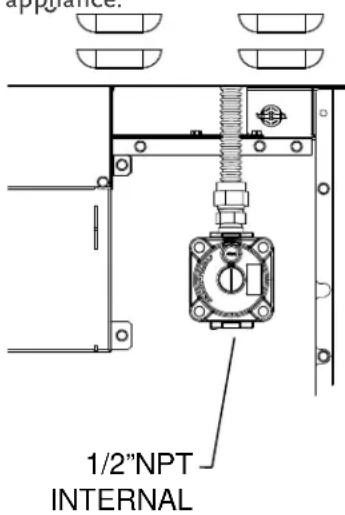
The gas connection at the back of the range (see below) features 1/2"NPT internal threads. Connect to gas supply using a minimum 3/4" inside diameter (1" OD) flexible (semi-rigid) stainless steel gas hose with appropriate end fittings to prevent gas starvation. This hose should be no more than 48" [1.2 m] in length. Use the appropriate thread sealant on all connections. Do not apply sealant to flare fittings.
The supply line must not interfere with the rear of the range. Use caution when pushing the range against the back wall, so that you do not kink or crimp the flex hose as this could result in a gas leak.
CONVERSION KITS
In the event your Hestan appliance needs to be converted from NG to LP, or vice-versa, you will need to contact Hestan Customer Service to arrange a service call. This conversion should only be performed by a qualified technician.
HIGH ALTITUDE KITS
If you live in a high altitude area, 2,000 ft. [610 m] or more above sea level, your appliance may require different orifices for proper combustion and performance. You will need to contact Hestan Customer Service to arrange a service call. High Altitude kits must be installed by a qualified technician. Please have your model and serial number information ready when you call.
To ensure proper heating performance of this appliance, verify that the gas line supply pressure is adequate. The appliance is supplied with a gas pressure regulator already installed. This regulator is set for a supply (inlet) pressure of 7-14 inch WC [1.74-3.48 kPa] to maintain 5 inch WC [1.24 kPa] nominal outlet (manifold) pressure.
Ensure that the service pipe supplying the appliance is fitted with a shut-off valve conveniently positioned and easily accessible as an emergency gas shut-off.
GAS CONNECTION - LIQUID PROPANE (LP)
If you purchased an LP version of your appliance, it will be supplied with a gas pressure regulator already installed. This regulator is set to maintain 10 inch WC [2.49 kPa] nominal outlet (manifold) pressure.
Ensure that the service pipe supplying the appliance is fitted with a shut-off valve conveniently positioned and easily accessible as an emergency gas shut-off.
When connecting to LP gas, verify the tank is equipped with its own high pressure regulator. The pressure of the gas supplied to the appliance must be 11-14 inch WC [2.74-3.48 kPa].
LEAK TESTING
GENERAL
Although all gas connections on your Hestan appliance are leak tested at the factory prior to shipment, a complete gas tightness check must be performed at the installation site due to possible movement in shipment, or excessive pressure unknowingly being applied to parts of the unit. Immediately check if the smell of gas is detected. Leak testing of the appliance shall be conducted according to these instructions:
BEFORE TESTING
WARNING
DO NOT SMOKE WHILE LEAK TESTING.
- Never leak test with an open flame.
- Make a soap solution of one part liquid detergent and one part water for leak testing purposes.
- Apply the solution to the gas fittings and flex hose by using a spray bottle or a brush.
TO TEST
- Make sure all control knobs are in the "OFF" position.
- Apply the soap solution to all fittings and flex hose.
- Turn the gas supply on.
- Check all connections from the supply line up to the regulator connection at the rear of the appliance.
- Soap bubbles will appear where a leak is present. If a leak is present, immediately turn off gas supply, tighten any leaking fittings, turn the gas supply back on, and recheck.
- If you cannot stop a gas leak, turn off the gas supply and call the dealer where you purchased your appliance.
- Do not use the appliance until all connections have been checked and do not leak.
FINAL SETUP
Remove any final packaging materials, and protective film from all exterior areas. Check inside oven for other packaging items, tape on oven racks, etc. Install any loose items like sealed burner heads, cooking grates, etc. Ensure the sealed burner heads are properly installed and seated on the burner base as shown below. There are notches on the burner base and cross ring to help with alignment. The outer burner head features a long slot on the top of the head which aligns with the spark igniter. Assembly of the single-flow burner head is similar.
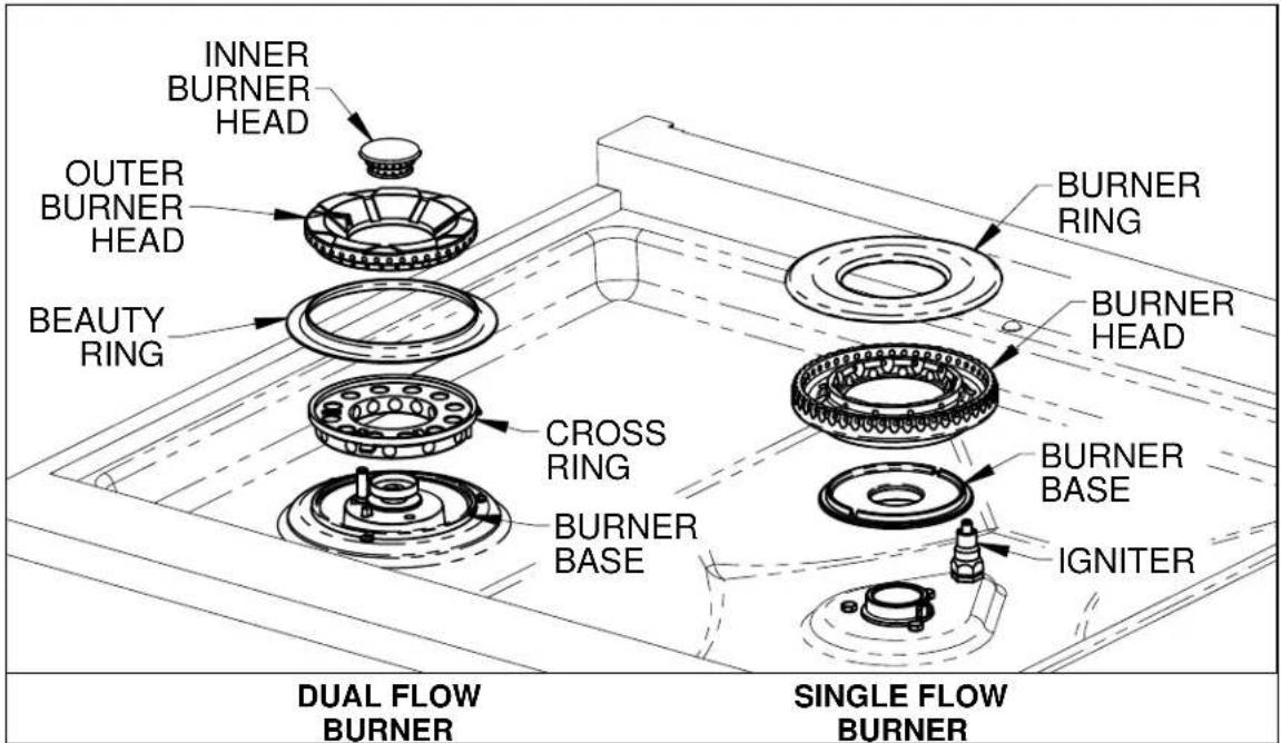
Before testing operation of the appliance, verify the leak check was performed and the electrical power has been restored to the unit. Turn the gas shut-off valve to the open position.
NOTICE
All the control knobs must be in the OFF position to prevent unintended operation at power up.
In the event of a power failure, the oven will shut off. The surface burners will continue to burn, but must be ignited manually with suitable lighter or match. When the power is restored, the oven will not operate until the oven knobs are in the OFF position. Set all the knobs to OFF, and resume normal use.
DO NOT ATTEMPT TO USE THE RANGE DURING A PROLONGED POWER FAILURE.
Verify ignition at each burner. Igniter will make a clicking sound until the flame lights within 4 seconds, then the clicking will stop. Check flame characteristics at each burner per the descriptions below. Flames should be stable and not dance or lift off the burner ports. Flame may need to burn for a few minutes to purge the gas lines of impurities. These appear as intermittent orange tips or even tiny sparks in the flame. This is normal and the flame will eventually stabilize like those shown in the image below.
If after a few minutes the flames continue to burn mostly yellow, verify that the burner head is properly installed on top of the base, then retest. Use caution when handling the burner head. They can be very hot.
Turn down the control knob to the simmer setting to check function.
Check each burner individually, then check they operate satisfactorily with other burners on.
GAS FLAME APPEARANCE
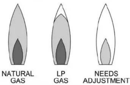
Light blue flame - Natural gas normal flame
Light blue flame with yellow tips - LP gas normal flame Yellow flame - Needs adjustment
GAS GRIDDLE
The gas griddle does not have flame/burner adjustments. Turn the control knob to HIGH, verify that the griddle heats up. You may also notice a constant orange glow at the rear vents of the griddle area. This is normal during operation of the griddle.
Turn all burners off when testing is complete.
If after all the above tests still result in mostly yellow flames, or the burners do not light, contact Hestan customer service to schedule a service call.
OVEN OPERATION
All rangetop checks to be performed prior to oven operation check.
Open and close oven door to check oven lights illuminate on opening, and fade once closed. Cycle oven lights using control panel switch to validate proper function.
With the door open, set mode knob to BAKE and temperature knob to 350^ F. Both knob backlights will illuminate and the orange "heating" indicator light will turn on. Bake igniter (located below bottom drip pan) begins to glow and once it reaches proper temperature, the gas valve is energized. Verify ignition and flame characteristics of bake burner.
Close the oven door. Set mode knob and temperature knob to BROIL. Both knob backlights will illuminate and the orange "heating" indicator light will turn on. Broil igniter (located at top of oven cavity) begins to glow and once it reaches proper temperature, the gas valve is energized. Verify ignition and flame characteristics of broil burner.
Turn oven off.
NOTE: A small amount of smoke and odor may be noticed during this test, and during the initial break-in period.
SERVICE
All warranty and non-warranty repairs should be performed by qualified service personnel. To locate an authorized service agent in your area, contact your Hestan dealer, local representative, or Hestan. Before you call, please have the model number and serial number information on hand.
Hestan Commercial Corporation
3375 E. La Palma Avenue
Anaheim, CA 92806
(888) 905-7463
| TABLE 1: BACKGUARD OPTIONS | ||
| RANGE MODEL BACKGUARD/MODED DESCRIPTION | DESCRIPTION | |
| KRG365 KBGIT36* BACKGUARD, ISLAND TRIM, 36" * | ||
| KBGLB36 BACKGUARD, LOW BACK, 36" | ||
| KBGHS36 BACKGUARD, HIGH SHELF, 36" | ||
| KRG364GD KBGIT36* BACKGUARD, ISLAND TRIM, 36" * | ||
EN
* INCLUDED WITH RANGE
⚠️ AVERTISSEMENT
LE NON-RESPECT À LA LETTRE DE CES INSTRUCTIONS PEUT CAUSER UN INCENDIE OU UNE EXPLOSION, QUI POURRAIT ENTRAÎNER DES DOMMAGES MATÉRIELS, DES BLESSURES OU LA MORT.
natural_image
Silhouette of a person pushing a large block on a horizontal line (no text or symbols)natural_image
Silhouette of a person in motion, possibly running or jumping, with no visible text or symbols.ALIMENTATION ÉLECTRIQUE
natural_image
Top-down view of a four-tiered gas stove with lattice windows and central hub (no text or symbols)KRG365 KRG364GD
natural_image
Top-down architectural rendering of a four-gate kitchen stove with lattice grilles and a side panel (no text or symbols)KRG364GD
PLAQUE SIGNALÉTIQUE
RESPECT DE LA RÉGLEMENTATION ET DES CODES EN VIGUEUR
natural_image
Technical line drawing of a mechanical assembly with no visible text or symbols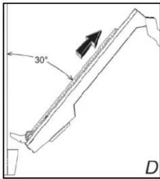
RÉINSTALLATION DE LA PORTE DU FOUR
natural_image
Technical line drawing of a mechanical assembly with labeled component 'F' (no text or symbols beyond label)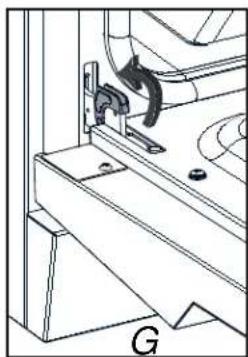
natural_image
Technical line drawing of a mechanical assembly with no visible text or symbols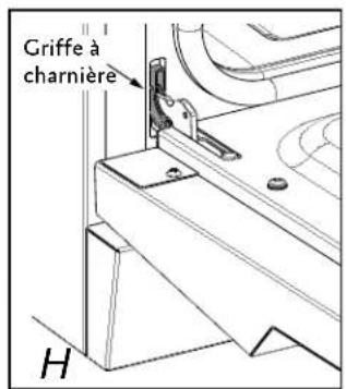
natural_image
Silhouette of a person in motion, possibly shooting or swinging a rope (no text or symbols)Hestan Commercial Corporation
3375 E. La Palma Avenue
Anaheim, CA 92806
(888) 905-7463
| TABLEAU 1: OPTIONS DU DOSSERET | ||
| MODÈLE DE CUISINIÈRE | MODÈLE DE DOSSERET LA DESCRIPTION DESCRIPTION | |
| KRG365 KBGIT36* | DOSSERET, PROFILE POUR ÎLOT, 36 PO * | |
| KBGLB36 | DOSSERET, ARRIÈRE BAS, 36 PO | |
| KBGHS36 | DOSSERET, ÉTAGÈRE HAUTE, 36 PO | |
| KRG364GD KBGIT36* | DOSSERET, PROFILE POUR ÎLOT, 36 PO * | |
| KBGLB36 | ||
| KBGHS36 | ||
* INCLUS AVEC CUISINIÈRE
CETTE PAGE N'EST PAS UTILISÉE.
FR
RETAIN THIS MANUAL FOR FUTURE REFERENCE CONSERVEZ CE MANUEL POUR UNE RÉFÉRENCE FUTURE

HESTAN
Hestan Commercial Corporation
3375 E. La Palma Ave.
Anaheim, CA 92806
(888) 905-7463

- INDOOR COOKING
- WARNING
- WHAT TO DO IF YOU SMELL GAS:
- SAFETY DEFINITIONS
- TIP OVER HAZARD
- TABLE OF CONTENTS
- SAFETY PRECAUTIONS - BEFORE YOU BEGIN
- ELECTRICAL SHOCK HAZARD
- ELECTRICAL GROUNDING
- ELECTRICAL SUPPLY
- RATING LABEL
- REGULATORY/CODE REQUIREMENTS
- STATE OF MASSACHUSETTS
- CALIFORNIA PROPOSITION 65 - WARNING
- LOCATION AND INSTALLATION / VENTILATION
- UNPACKING AND PLACEMENT
- LOCATION AND INSTALLATION / VENTILATION(CONTINUED)
- PREPARATION
- GAS AND ELECTRICAL SUPPLY CLEARANCES
- CABINETRY
- LOCATION AND INSTALLATION/VENTILATION (CONTINUED)
- OVEN DOOR REMOVAL
- RE-INSTALL OVEN DOOR
- LOCATION AND INSTALLATION/VENTILATION(CONTINUED)
- LEVELING
- NOTES:
- SIDE VIEW
- VENTILATION REQUIREMENTS
- BACKGUARD AND ACCESSORIES
- CAUTION
- BACKGUARD
- INSTALLATION OF ANTI-TIP DEVICE
- NOTICE
- HOLE PREPARATION
- INSTALLATION OF ANTI-TIP DEVICE (CONTINUED)
- ANTI-TIP BOLT ADJUSTMENT
- ELECTRICAL CONNECTION
- GAS SUPPLY
- CONVERSION KITS
- HIGH ALTITUDE KITS
- GAS CONNECTION - LIQUID PROPANE (LP)
- LEAK TESTING
- GENERAL
- BEFORE TESTING
- DO NOT SMOKE WHILE LEAK TESTING.
- TO TEST
- FINAL SETUP
- GAS GRIDDLE
- OVEN OPERATION
- SERVICE
- ⚠️ AVERTISSEMENT
- ALIMENTATION ÉLECTRIQUE
- PLAQUE SIGNALÉTIQUE
- RESPECT DE LA RÉGLEMENTATION ET DES CODES EN VIGUEUR
- RÉINSTALLATION DE LA PORTE DU FOUR
- RETAIN THIS MANUAL FOR FUTURE REFERENCE CONSERVEZ CE MANUEL POUR UNE RÉFÉRENCE FUTURE
Brand : Hestan
Model : KRG365
Category : Cooker