
Pro Cut 461B - Lawn mower Texas - Free user manual and instructions
Find the device manual for free Pro Cut 461B Texas in PDF.


User questions about Pro Cut 461B Texas
0 question about this device. Answer the ones you know or ask your own.
Ask a new question about this device
Download the instructions for your Lawn mower in PDF format for free! Find your manual Pro Cut 461B - Texas and take your electronic device back in hand. On this page are published all the documents necessary for the use of your device. Pro Cut 461B by Texas.
USER MANUAL Pro Cut 461B Texas
natural_image
Line drawing of a lawn mower with adjustable arm and wheels (no text or symbols) | Advarsel:Sikkerhedsinformationomkring situationer der kanende i personskade | Warning:Safety information abouthazards that can result inpersonal injury |
 | Læs betjeningsvejledningengrundigt før maskinenbenyttes. | Please read the user manualcarefully before operating themachine. |
 | Advarsel:Risiko for flyvende objekter | Warning:Risk of flying objects |
 | Hold afstand til personer,børn og dyr | Keep distance to otherpeople, children and animals |
 | Udsæt ikke udstyret for regn/vand og opbevardet indendørs. | Do not expose the equipment to rain/water andstore it indoor. |
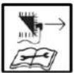 | Fjern tændrør inden du udførervedligeholdelse, rengøring og inden duforlader maskinen uden opsyn. | Remove spark plug before carrying out anymaintenance, cleaning and before leaving themachine unattended. |
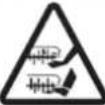 | Advarsel:Indsæt ikke hænder ellerfødder under skjoldet | Warning:Do not put hands or feet under the deck |
 | Advarsel:Brug ikke maskinen indendørs, i lukkede ogdårligt ventilerede områder | Warning:Do not use machine indoor, in closed or poorlyventilated environments |
 | Advarsel:Farlig udstødningsgas | Warning:Toxic exhaust fumes |
 | Brug høreværn og sikkerhedsbriller Use hear protection and safety goggles |
text_image
Technical diagram of a lawn mower with numbered parts for identificationFig. 2
natural_image
Technical line drawing of a mechanical vehicle's front wheel assembly (no text or symbols)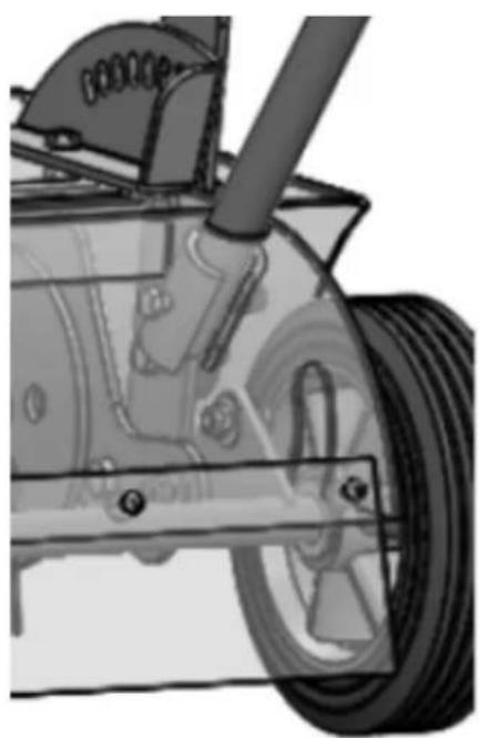
natural_image
Mechanical assembly diagram showing a wheel, suspension components, and mechanical parts (no text or symbols)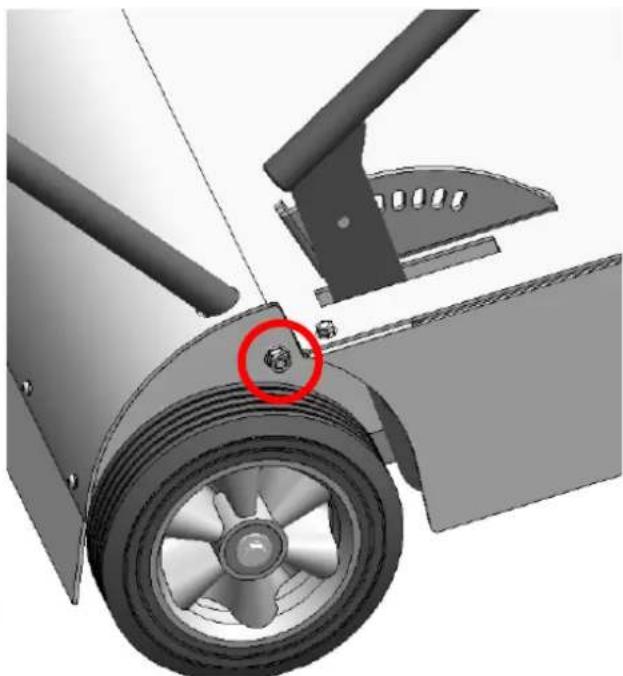
natural_image
Mechanical component diagram showing a wheel assembly with a red circle highlighting a specific part (no text or symbols present)Fig. 3
natural_image
Technical line drawing of a mechanical device with a red circle highlighting a component (no text or symbols present)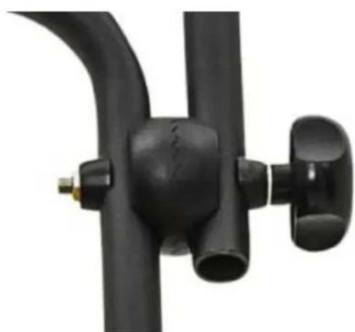
natural_image
Close-up of a black plastic mechanical component with curved and flanged ends (no text or symbols visible)Fig. 4
natural_image
Close-up of a black lawn mower frame with attached motors and cable, showing no text or symbolsFig. 5
natural_image
Mechanical component diagram showing a wheel assembly with a red arrow pointing to a specific part (no text or symbols present)Fig. 6
natural_image
Close-up of a mechanical device with visible springs and adjustment knobs (no text or symbols)
text_image
Traffic sign indicating fuel pump and directional arrows, commonly used for parking or refueling services.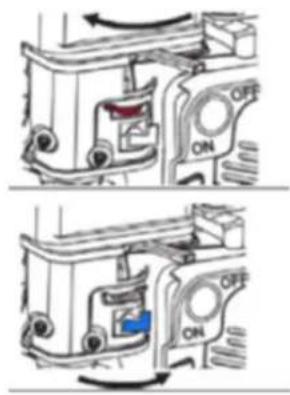
text_image
Technical diagram showing two views of a mechanical device with labeled ON/OFF states and directional arrows indicating movement or force.
text_image
2 9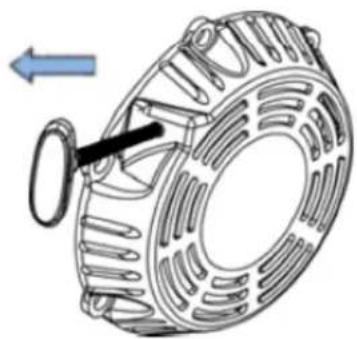
natural_image
Technical illustration of a mechanical component with internal structure and directional arrow (no text or symbols)Fig. 7
natural_image
Diagram of a coiled tube or coil structure with directional arrows, no text or symbols present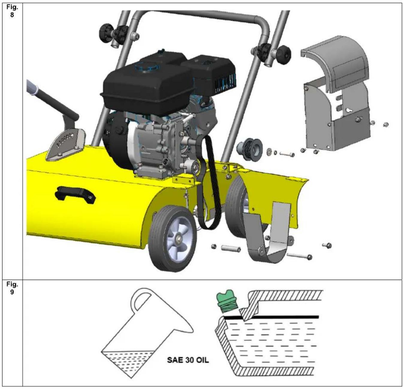
text_image
Fig. 8 Fig. 9 SAE 30 OILDK Original brugsanvisning
Advarselssymboler....2
Illustrationer....4
GB Original instructions
Warning symbols 2
Illustrations....4
- Safety 12
- Identification of the parts 12
- Unpacking and mounting.... 12
- Adjustment of working depth 13
- Start / Stop 13
- Operation 13
- Replacement of belt 13
- Changing engine oil 13
- Air filter 14
- Storage and maintenance 14
- Specifications 14
- Warranty terms and conditions.... 14
EC Declaration of conformity.... 27
1. Safety
Setup
Do not put hands or feet near or under rotating parts.
Read this manual carefully. Make sure that you are familiar with the different controls, settings and handles of the equipment.
Know how to stop the unit and ensure that you are familiar with emergency stop.
A. Never allow children or people unfamiliar with these instructions to use the machine. Note, that local regulations can restrict the age of the operator.
⚠️ If you feel unwell, tired or have consumed alcohol or drugs, do not operate the machine.
Always inspect the machine before usage Ensure that no parts are worn or damaged.
⚠️ Replace worn out or damaged elements and bolts in sets to preserve balance.
The operator of the machine is responsible for people's safety.
⚠️ Never use the machine near children or animals.
The operator of the machine is held liable for any accidents or hazards to other people and their property.
A. Thoroughly inspect the area, where the equipment is to be used, if necessary remove any foreign objects.
⚠ Boots with non-slip soles with steel jacket is required. Avoid loose-fitting clothes.
Operation
After striking a foreign object, stop the engine immediately and inspect the machine thoroughly for damage. Repair the damage before continuing.
A. If the machine should start to vibrate abnormally, stop the engine and check immediately for the cause. Vibration is generally a warning of damage.
Always turn off the engine and ensure that all moving parts have come to a complete stop before making any repairs, adjustments, or inspections.
Exercise extreme caution when operating on slopes.
⚠️ Never operate the machine at a fast pace.
Do not overload machine capacity by attempting to push at too fast a rate.
Do not carry passengers.
⚠️ Never allow any bystanders in front of unit.
Only operate the machine at daylight or in fully illuminated areas.
⚠ Ensure a stable foothold and always keep a firm hold on the handles. Always walk, never run.
Do not operate the machine when barefoot or wearing sandals.
Exercise extreme caution when changing direction on slopes
Never attempt to make any adjustments, while the engine is running.
Use extreme caution when reversing or pulling the machine backwards
Due to vibrations from the handle, long time use can result in white fingers.
If fatigue is felt in arms, hands or fingers – or visible signs of white fingers is appearing, the work should be stopped immediately, and a sufficient time of break should be taken for recovery. To avoid white fingers, each user should operate the machine for no more than 1.5 hours straight per day.
Maintenance and storage
The engine shall be stopped when carrying out maintenance and cleaning operations, when changing tools and when being transported by means other than under its own power.
Check regularly that all bolts and nuts are tightened. Retighten if necessary.
The engine must be completely cooled before storing indoors or covered.
If the machine unused for a period of time, please refer to the instructions in this manual.
Maintain or replace safety and instruction labels, as necessary.
A Only use orginal spare parts or accessories. If not orginal parts or accessories is used, the liability is no longer applied.
Miscellaneous
A Factory-fitted control devices, such as the handle-mounted clutch cable, must not be removed or exposed.
⚠ Ensure that the machine is properly secured when transported on a flatbed etc.
2. Identification of the parts
See Fig. 1
- Upper handlebar
- Throttle control
- Recoil starter handle
- Lifting handle
- Wheel
- Height adjustment handle
- Engine
- Finger knobs
- Blade clutch handle
3. Unpacking and mounting
Unpacking:
Remove the machine from the box by pulling the machine out from the box. The box contains:
1 pcs. scarifier
1 pcs. user manual
1 pcs. engine manual
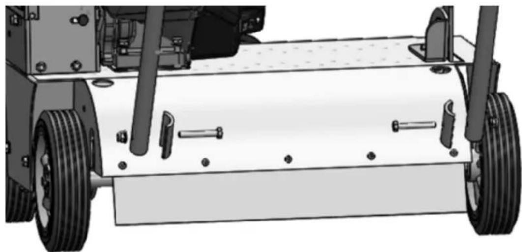
Mounting the handlebar: See Fig. 2, 3, 4
- Fix the lower handlebar to the machine. Lower handlebar must be fitted with tension plates inside the deck Fix with bolts and nuts (Fig. 2)
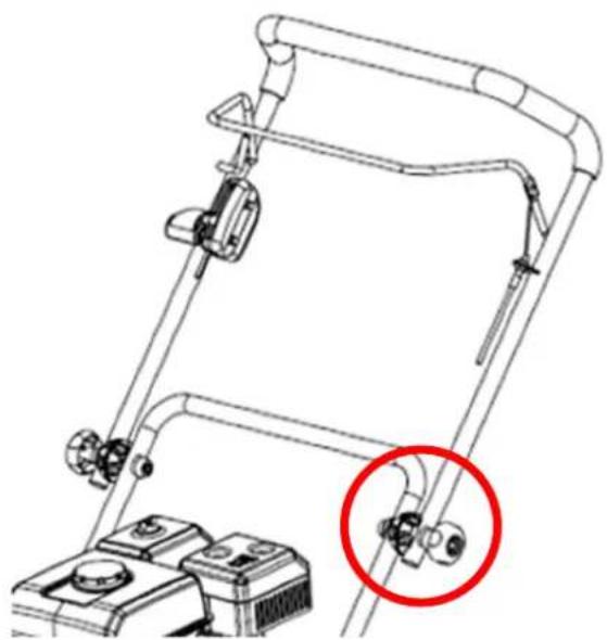
- Connect upper handlebar to lower handlebar using the finger knobs and tight it in the desired position/angle (Fig. 3)
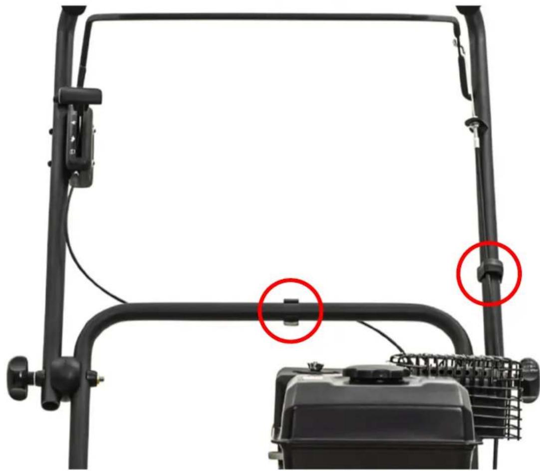
- Adjust cables and secure cable clamps (Fig. 4)
4. Adjustment of working depth
Stop the engine completely before the working depth is adjusted.
See Fig. 5
The working depth can be adjusted by mowing the height adjustment handle. The working depth (7 positions) range between +5 mm transport position) and down to -30 mm.
Important: When the machine is transported from one place to another, the engine must be switched off. Make sure to put the height adjustment handle in "transport position", so that the blades do not touch the ground.
5. Start / Stop
Always check the oil level before start!
The oil level must always be between the min. and max. Mark on the dipstick. Always use SAE-30 oil. Use only unleaded E5 gasoline. Never over-fill the gas tank.
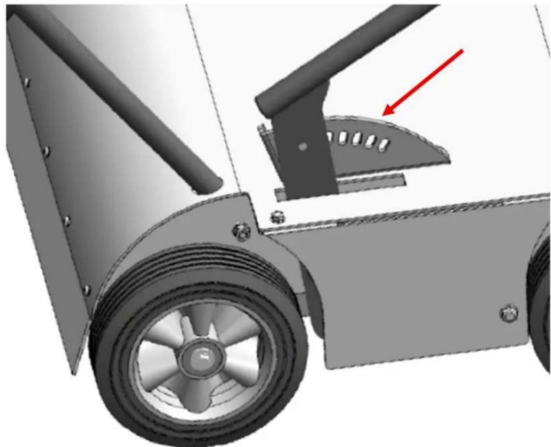
Stay behind the handlebar, while starting the engine! Always raise the blades by putting the height adjustment handle in "transport position" (Fig. 5).
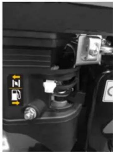
Starting the engine: See Fig. 6
- Put transport lever in "transport position"
- Open the fuel tap
- Position the choke at max. Move the choke lever fully to the left. The choke is not required if the motor is hot.
- Set throttle control lever to maximum (2)
- Pull the start cord to start the motor. Always feed the start cord back into the motor by hand.
- When the motor starts, set the choke to minimum.
- Activate the blades by holding the blade clutch handle (9).
For B&S engine, see the engine manual for chokes and fuel tap function.
Important: The blade clutch handle fully activated during operation, i.e. the handle must be held tight up against the upper handlebar.
The blades stop rotating when the blade clutch handle is released.
Stopping the engine: See Fig, 6
- Release the blade clutch handle (9)
- Move the throttle control lever to minimum (2)
- Close the fuel tap
Vibrations may travel up into the handle during use. We therefore recommend taking a break every 30 minutes.
6. Operation
The scarifier is used to loosen moss, etc. from the lawn. The machine's blades rotate in the direction of travel, thereby helping to drive the machine forward.
Important: Do not use the scarifier when the soil is very hard and dry. It can damage the belt. Use the scarifier in early spring and autumn, where the soil is normally moistures and soft.
Never use the machine if the grass is longer than 75 mm. Always start use the machine with in one of the higher working depth positions.
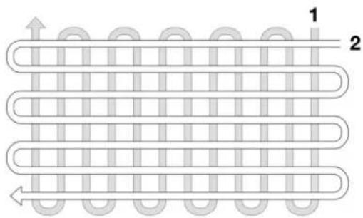
Working pattern: See Fig. 7
Move the lawn spiker forwards and backwards across the lawn. After the first aeration remove any lose moss from the lawn. If there is still moss in the lawn, aerate again at an angle of 90 degrees to the previous aeration.
Warning: If the working condition does not allow the motor to work at full speed, the motor power will drop. If you hear a change in sound, stop working. Release the switch lever and raise the working depth. Failure to do so could damage the machine.
When to use the aerator/scarifier roll
- The aerator roll (blades) is used to aerate the the lawn, providing more air to the roots of the grass, so it can grow stronger and prevent moss.
- The scarifier roll (springs) is used to remove already existing moss in the lawn.
It is recommended to use both rolls in combination at least 2 times a year on your lawn: Spring and autumn, when the soil is moistures and soft. Never in hard and dry soil conditions and only when the ground is completely free of frost.
7. Replacement of belt
⚠️ Stop the engine and remove spark plug cap before any work under the deck.
Follow Fig. 8 for how to disassemble machine, so belt can be replaced.
8. Changing engine oil
The oil should initially be changed after the first 5 hours of use, and thereafter once per year.
- Let the motor run for 5 minutes to heat up the oil. This allows the oil to run more freely and makes for a more complete oil change.
- After 5 minutes, stop the motor. Remove the spark plug cap. Drain the oil by unscrewing the sump plug. Remember to drain the oil into a container of sufficient capacity. NB: The motor must not be tipped backwards more than 45 degrees.
- Screw the sump plug back in and pour new oil into the motor. Do this by removing the dipstick and pouring in the recommended quantity of oil.
- Refit the spark plug cap.
- Fill the engine with new SAE-30 oil.
- Check if the oil level reaches the edge of the filling hole (See Fig. 8).
Alternatively, use an oil extractor kit. (oil and oil extractor kit are not included)
9. Air filter
Please inspect and clean the air filter on a regular basis. If the filter has not been cleaned for a longer period, this will have influence on the engines power take-off and the exhaustion.
- Clean around the air filter before it is removed
- Carefully remove the paper filter and check it. Brush it with a soft brush. If it is very dirty, it must be changed. Take care that no dirt gets into the intake of the engine.
- Wash the black foam element on the right side in warm soapy water.
- Press the water out of the foam element and let it dry. Put a few drops of SAE-30 oil on the filter to moisten it lightly with oil. Carefully squeeze out any surplus oil. Remount the element.
- Check that all parts are fitted correctly and close the cover.
10. Storage and maintenance
Maintain your machine: Check and tighten bolts and nuts before each use. After use remove any moss attached to the deck. Stop the motor, remove the spark plug cap and tip the machine back. Clean under the shield with a soft brush.
If cleaning the machine with a hose, use a low pressure so as to avoid damaging the machines stickers. Also avoid spraying the blade bearing directly. After washing the machine, it is a good idea to start the machine and let it run without resistance for a short period of time.
Storage: Keep machine in a dry and clean room. Clean the machine after every use. Grass and dirt must be removed from the underside of the deck.
Winter storage: Spray silicone lubrication into the cables and move them. Finally, clean the mower thoroughly. Dip a cloth in oil and luricate metal parts to prevent rust.
11. Specifications
| Model Pro Cut 461TG / 461B | |
| Engine TG725 - 212 cc | |
| B&S XR950 - 208 cc | |
| Drive | Push |
| Fuel tank capacity 3.6 L | |
| Oil tank capacity 0.6 L | |
| Drive | Push |
| Working width 46 cm | |
| Working depth -30 mm to +5 mm | |
| Net weight 69.5 kg | |
| Guaranteed L_wA | 99 dB(A) |
12. Warranty terms and conditions
The warranty period is 2 years for private end users in EU countries. Products sold for commercial use, only have a warranty period of 1 year.
The warranty covers material and/or fabrication faults.
Restrictions and requirements
Normal wear and replacement of wearing parts are NOT covered by the warranty.
Wearing parts, which are NOT covered for more than 12 months:
- Blades/springs
- Cables
- Belts
The warranty does NOT cover damages/faults caused by:
- Lack of service and maintenance
• Structural changes - Exposure to unusual external conditions
- Damages to the bodywork, deck, handles, panels etc.
- If the machine has been improperly used or overloaded
- Wrong handling or storage of the battery
- Wrong use of oil, gasoline or other liquid types, which are not recommended in this user manual
- Bad or dirty gasoline, which results in contamination of the fuel system
- Use of unoriginal spare parts.
- Other conditions where Texas cannot be held responsible.
Whether a case is a warranty claim or not is determined in each case by an authorized service center.
Your receipt is your warranty note, why it should always be kept safe.
REMEMBER: The purchase of spare parts as well as any request for warranty repair, art. number (e.g. 900611XX), year and serial number should always be informed. It can be found on the CE-label located on top of the rear part of deck!
* We reserve the right to change the conditions and accept no liability for any misprints
2006/42/EC - 2000/14/EC amended by 2005/88/EC
Materiellet er udført i overensstemmelse med følgende standarder • Conforms with the following standards • In Übereinstimmung mit den folgende Standards • Conformément aux normes suivantes • Conformemente ai seguenti standard
EN709:1997+A4:2009/AC:2012
L_wA : 99 dB(A) L pA: 83.5 dB(A) A_h : 2.840 m/s ^2
Pro Cut 461TG Serial numbers: 2501390001 - 2712399999 Pro Cut 461B Serial numbers: 2501400001 - 2712409999
Texas Andreas Petersen A/S Knullen 22 • DK-5260 Odense S 01.08.2025
Responsible for documentation Johnny Lolk
text_image
Henry TahnJohnny Lolk Managing Director