
RAK149F2A - Air Conditioning GE - Free user manual and instructions
Find the device manual for free RAK149F2A GE in PDF.

| Product Type | Air Conditioner and Heat Pump Thermostat |
| Brand | GE |
| Model | RAK149F2A |
| Dimensions (H x W x D) | 95 x 152 x 29 mm (3-3/4 x 6 x 1-1/8 in) |
| Power Supply | 20 to 30 VAC, 50/60 Hz, NEC Class II |
| Maximum Load per Terminal | 1.5 A per terminal, 2.5 A max total |
| Temperature Setpoint Range | 16 to 29 °C (60 to 85 °F) |
| Operating Temperature Range | 0 to 41 °C (32 to 105 °F) |
| Display Temperature Range | 0 to 37 °C (32 to 99 °F) |
| Operating Humidity | 90% max non-condensing |
| Number of Heat/Cool Stages | Cooling 1 stage, heating 1 or 2 stages (heat pump + backup) |
| Fan Speed | 2 speeds (high and low) |
| Main Functions | Heating and cooling control, fan mode, compressor lockout, cycle adjustment, digital display |
| Backlight | Momentary or continuous (depending on setting) |
| Temperature Units | Fahrenheit or Celsius |
| Safety | Do not exceed rated voltage; disconnect power before installation; do not short circuit terminals |
| Compatibility | Heat pump (type B) or Packaged Terminal Air Conditioner (PTAC) |
| Reset | Factory settings: hold ▲ and ▼ while switching from OFF to HEAT |
| Wiring Terminal | GL (low fan), GH (high fan), R (24 V), O/B (reversing), Y (compressor), W (2nd stage heat), C (common) |
| Standards | FCC Part 15 Class B, ICES-003 (B) / NMB-003 (B) |
Frequently Asked Questions - RAK149F2A GE
User questions about RAK149F2A GE
0 question about this device. Answer the ones you know or ask your own.
Ask a new question about this device
Download the instructions for your Air Conditioning in PDF format for free! Find your manual RAK149F2A - GE and take your electronic device back in hand. On this page are published all the documents necessary for the use of your device. RAK149F2A by GE.
USER MANUAL RAK149F2A GE
Hardwired, 2 Fan Speeds
THERMOSTAT
OWNER'S MANUAL AND INSTALLATION INSTRUCTIONS
RAK149F2A
SPECIFICATIONS ......2
INSTALLATION INSTRUCTIONS
WIRING....3
INSTALLER MENU 4
TEST EQUIPMENT 6
USING THE THERMOSTAT
OVERVIEW......7
TROUBLESHOOTING 8
RESETTING 9
FCC STATEMENT ......10
SPECIFICATIONS
| Electrical Rating: | |||
| Input-Hardwire 20 to 30 VAC, NEC Class II, 50/60 Hz | |||
| Terminal Load 1.5 A per terminal, 2.5A maximum all terminals combined | |||
| Setpoint Range 60° to 85°F (16° to 29°C) | |||
| Rated Differentials (@ 6°F/ Hr): | Fast Med Slow | ||
| Heat Pump (Heating) 0.9°F 1.2°F 1.7°F | |||
| Heat Pump (Cooling) 0.9°F 1.2°F 1.7°F | |||
| Auxiliary Heat 0.5°F 0.75°F 1.9°F | |||
| Operating Ambient 32°F to +105°F (0° to +41°C) | |||
| Display Temperature Range | 32°F to +99°F (0 to 37°C) | ||
| Operating Humidity. 90% non-condensing maximum | |||
| Shipping Temperature Range | -20°F to +150°F (-29° to +65°C) | ||
| Thermostat Dimensions 3-3/4" H x 6" W x 1-1/8" D | |||
MERCURY NOTICE: This product does not contain mercury. However, this product may replace a product that contains mercury. Mercury and products containing mercury must not be discarded in household trash. Refer to thermostat-recycle.org for information on disposing of products containing mercury.
| Thermostat Applications Maximum Stages Heat/ Cool | |
| Single Stage Cooling, One or Two Stage HeatingNOTE: Two stage heating = 1st stage heat pump and 2nd stage resistance heat | 2/1 |
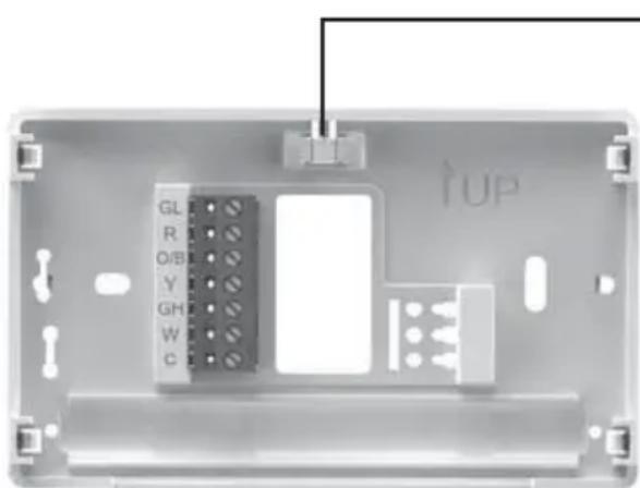
WIRING
Refer to equipment manufacturer's instructions for specific system wiring information. After wiring, see INSTALLER MENU for proper thermostat configuration. Wiring table shown are for typical systems and describe the thermostat terminal functions.
| Terminal Designations | Terminal Function |
| GL Low Speed | Fan Relay |
| R Power (24V) | |
| O/B Changeover | Terminal-Energized in Cool (O) or Heat (B) for Heat PumpNote: All Zoneline/Hotpoint applications are B type heat pump. |
| Y Heat and Cool Mode 1st Stage Compressor | |
| GH High Speed | Fan Relay |
| W Heat Mode | - 2nd Stage Heat (Electric) |
| C Common wire for 24V | |
natural_image
Interior view of a device casing showing internal components and wiring (no readable text or symbols)Leveling Thermostat
Leveling is for appearance only and will not affect thermostat operation.
Precautions
- Do not exceed the specification ratings.
- All wiring must conform to local and national electrical codes and ordinances.
- This control is a precision instrument, and should be handled carefully. Rough handing or distorting components could cause the control to malfunction.
WARNING
Do not use on circuits exceeding specified voltage. Higher voltage will damage control and could cause shock or fire hazard. Do not short out terminals on primary control to test. Short or incorrect wiring will burn out thermostat and could cause personal injury and/or property damage.
CAUTION
To prevent electrical shock and/or equipment damage, disconnect electrical power to system, at main fuse or circuit breaker box, until installation is complete.
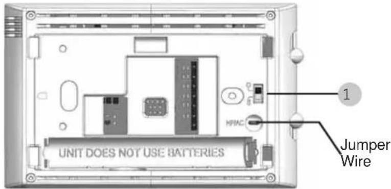
WIRING (cont)
Instructions: To convert the system from PTHP to PTAC, change menu item #20 from default HP to AC. Additionally, if you are using this thermostat on a Hotpoint PTAC (non-heat pump), you will need to cut the jumper wire located on the back of the thermostat.
Note: Menu item #32 will not be displayed in AC mode.
1.) O/B Terminal Switch
The O/B switch on this thermostat is factory set to the B position. This will accommodate heat pump applications, which require the changeover relay to be energized in Heat. If the heat pump being installed requires an O terminal to energize the changeover relay in Cool, the O/B switch must be moved to the O position.
INSTALLER MENU
To access the INSTALLER'S MENU, set the system switch to the OFF position and then press and hold the temperature ▲ and ▼ buttons for 3 seconds. The display will show item 20 in the table. Use the temperature ▲ and ▼ buttons by pressing them simultaneously to navigate through menu items. Press ▲ or ▼ to change a menu setting. To exit the Installer's Menu at any time, move the system switch to Heat or Cool.
INSTALLER MENU (cont)
| Installer's Menu # (Hold Menu 3 Seconds) | Description Default | Setting (flashing icons) | Settings (Press ▲ or ▼) |
| 20 | Algorithm - AC or HP (If HP is selected, item #32 will be displayed) | HP HP - H | heat Pump or AC - Air Cond. |
| 30 CR | Heat Cycle Rate (how often the heat will turn on) | SLO SLO - | slow MEd - medium FAS - fast |
| 32 CR | Aux Cycle Rate (how often the auxiliary heat will turn on) Note: Available if HP is selected on item #20 | SLO SLO - | slow MEd - medium FAS - fast |
| 35 CR | Cool Cycle Rate (how often the cooling will turn on) | SLO SLO - | slow MEd - medium FAS - fast |
| 50 CL | Compressor Lockout (protects the compressor from short cycling) | OFF On - 5 | minute delay OFF - no delay |
| 65 | Maximum Heat Limit (maximum set point for heat mode) | 85°F 45°F to 99°F | |
| 66 | Minimum Cool Limit (minimum set point for cool mode) | 60°F 45°F to 99°F | |
| 79 | Fahrenheit or Celsius | °F | °F - Fahrenheit °C - Celsius |
| 81 | Temperature Display Adjustment (adjust the displayed “Room Temperature”) | 0 -5 to +5 | |
| 83 dL | Continuous Display Light (keep the backlight always on - “C” wire required) | OFF On - always on OFF - momentarily on for 8 seconds | |
TEST EQUIPMENT
Turn on power to the system.
Fan Operation
1.) Move fan switch to Low position. The blower should begin to operate at low speed.
2.) Move fan switch to Auto Low position. The blower should stop immediately.
3.) Move fan switch to High position. The blower should begin to operate at high speed.
4.) Move fan switch to Auto High position. The blower should stop immediately.
Heating System
1.) Move System Switch to Heat position.
2.) Press ▲ to adjust thermostat setting to 1° above room temperature. 1st stage heat should begin to operate.
3.) If 2nd stage resistance heat is being utilized, press ▲ to adjust the thermostat 3^ above room temperature. Resistance heat should begin to operate.
4.) Press ▼ to adjust the thermostat to 1° below the room temperature. The heating system should stop operating.
Cooling System
1.) Move System Switch to Cool position.
2.) Press ▼ to adjust thermostat setting 1° below room temperature. The blower should come on immediately, followed by cold air circulation. The thermostat will indicate Cool On. There can be up to a 5 minute delay. (see INSTALLER MENU, item 50)
3.) Press ▲ to adjust thermostat setting to 1° above room temperature. The cooling system should stop operating.
Note: The default position for the compressor lockout is OFF in the INSTALLER menu, item 50. When compressor lockout is turned ON Starting Soon will be visible on the display. If Starting Soon is shown on the display, the compressor lockout feature is operating. There will be up to a 5 minute delay before the compressor turns on.
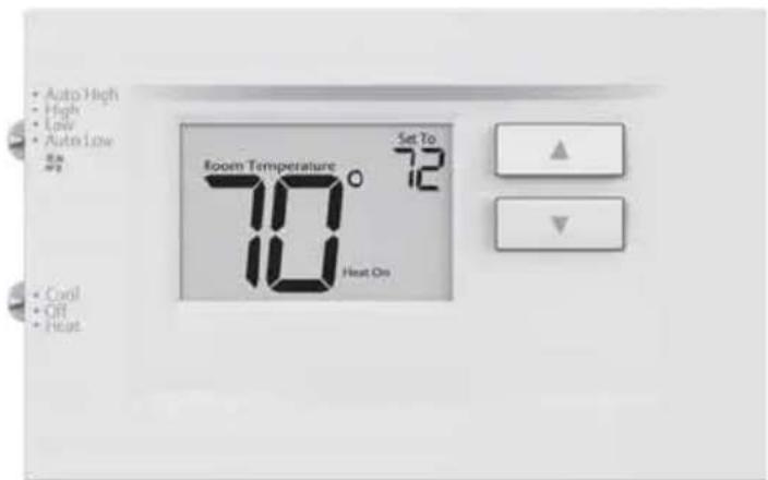
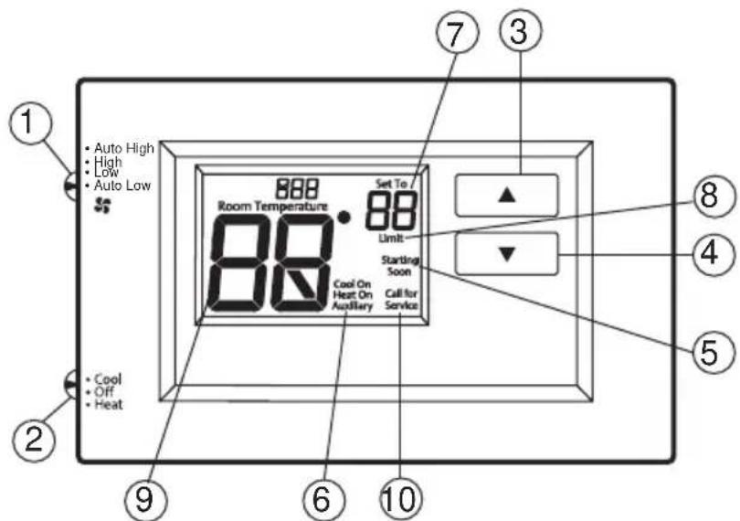
THERMOSTAT OVERVIEW
Before you begin using your thermostat, you should be familiar with its features, display and the location/operation of the thermostat buttons and switches.
| THERMOSTAT BUTTONS AND SWITCHES | THE DISPLAY |
| 1.) Fan Switch 5.) Thermostat is protecting the equipment from short cycling (5-minute delay) | |
| 2.) System Switch 6.) Indicates that the system is running in cool, heat or auxiliary mode (The auxiliary will run in Heat mode when the heat pump cannot maintain the set temperature.) | |
| 3.) Raises Temperature Setting 7.) Temperature setpoint | |
| 4.) Lowers Temperature Setting 8.) Displays when the thermostat setpoint has reached the maximum or minimum setting. | |
| 9.) Room Temperature | |
| 10.) SEE TROUBLESHOOTING | |
TROUBLESHOOTING
| Symptom Possible Cause Corrective Action | ||
| No Heat/ No Cool/ No Fan (common problem) | 1.) Blown fuse or tripped circuit breaker2.) HVAC unit unpowered3.) HVAC unit not set for remote thermostat control4.) Loose connection to thermostat or system | 1.) Replace fuse or reset breaker2.) Restore power to HVAC unit3.) Enable wall thermostat control on HVAC unit4.) Tighten Connections |
| No Heat/ No First Stage Heat | 1.) System Switch not set to Heat2.) Loose connection to thermostat or system3.) Heating System requires service or thermostat requires replacement4.) Misconfiguration between menu item 20 and jumper wire. | Verify thermostat and system wires are securely attached.Diagnostic: Set System Switch to Heat and raise the setpoint above room temperature. Within five minutes the thermostat should make a soft click sound and “Heat On” should appear on display. This sound indicates the thermostat is operating properly. If the thermostat does not click, try the reset operation listed below. If the thermostat does not click after being reset, contact your heating and cooling service person or place of purchase for a replacement. If the thermostat clicks, contact the furnace manufacturer or a service person to verify the heating system is operating correctly. Make sure that menu item 20 and the jumper wire match. |
| No Cool 1.) System | System Switch not set to Cool2.) Loose connection to thermostat or system3.) Cooling System requires service or thermostat requires replacement | Verify thermostat and system wires are securely attached.Diagnostic: Set System Switch to Cool and lower setpoint below room temperature. Same procedures as diagnostic for “No Heat” condition except set the thermostat to Cool and lower the setpoint below the room temperature. There may be up to a five minute delay before the thermostat clicks in Cooling if the compressor lock-out option is selected in the installer menu. (see INSTALLER MENU, item 50) |
| Heat, Cool or Fan Runs Constantly | Possible short in wiring, thermostat, heat, cool or fan system | Check each wire connection to verify they are not shorted or touching other wires. Try resetting the thermostat. If the condition persists contact your HVAC service person. |
| Thermostat Display & Thermometer Disagree | Thermostat display requires adjustment | Display can be adjusted +/-5°. See User Menu item 04 |
| Furnace (Air Conditioner) Cycles Too Fast or Slow (narrow or wide temperature swing) / No First Stage Heat | 1.) The location of the thermostat and/or the size of the Heating System may be influencing the cycle rate2.) Misconfiguration between menu item 20 and jumper wire. | Digital thermostats provide precise control and cycle faster than older mechanical models. The system turns on and off more frequently, but runs for a shorter time. If you would like to increase cycle time, choose SLO for slow cycle in the Installer menu. (Reference menu items 30 & 35) If an acceptable cycle rate is not achieved, contact your HVAC service person. |
| “Call for Service” icon appears on displayed | 1.) Heating system is not able to heat the space to within 10 degrees of the setpoint within 2 hours2.) Cooling system is not able to cool the space to within 10 degrees of the setpoint within 2 hours3.) If “--” is displayed for the Room Temperature, a replacement thermostat is needed4.) None of the buttons operate on the thermostat5.) If “Call for Service” is flashing, compressor self diagnostic is detecting an issue with the outdoor unit | 1.) See corrective action for “No Heat”2.) See corrective action for “No Cool”3.) Replace thermostat4.) Check for stuck buttons5.) Contact a service person to verify the equipment is operating correctly |
Resetting the Thermostat or Thermostat Settings
To conveniently reset only the user settings back to factory defaults, press ▲ and ▼ buttons while moving the system switch from OFF to HEAT at the same time and hold until the display goes blank and resets.
WARNING
This product contains a chemical known to the state of California to cause cancer and birth defects and other reproductive harm.
NOTE: This equipment has been tested and found to comply with the limits for a Class B digital device, pursuant to part 15 of the FCC Rules. These limits are designed to provide reasonable protection against harmful interference in a residential installation. This equipment generates, uses and can radiate radio frequency energy and, if not installed and used in accordance with the instructions, may cause harmful interference to radio communications. However, there is no guarantee that interference will not occur in a particular installation. If this equipment does cause harmful interference to radio or television reception, which can be determined by turning the equipment off and on, the user is encouraged to try to correct the interference by one or more of the following measures:
• Reorient or relocate the receiving antenna
- Increase the separation between the equipment and receiver
- Connect the equipment into an outlet on a circuit different from that to which the receiver is connected
- Consult the dealer or an experienced radio/TV technician for help
CAN ICES-003 (B) / NMB-003 (B)
TECHNICAL SUPPORT: 1-844-434-7822 Option 1
SPÉCIFICATIONS
natural_image
Top-down view of a device casing with labeled ports (GL, R, O/B, Y, GH, W, C) and a central component, no readable text or symbols beyond labels.- Hardwired, 2 Fan Speeds
- THERMOSTAT
- OWNER'S MANUAL AND INSTALLATION INSTRUCTIONS
- SPECIFICATIONS
- WIRING
- Leveling Thermostat
- Precautions
- WARNING
- CAUTION
- WIRING (cont)
- 1.) O/B Terminal Switch
- INSTALLER MENU
- TEST EQUIPMENT
- Fan Operation
- Heating System
- Cooling System
- THERMOSTAT OVERVIEW
- TROUBLESHOOTING
- Resetting the Thermostat or Thermostat Settings
- SPÉCIFICATIONS
Brand : GE
Model : RAK149F2A
Category : Air Conditioning