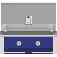
EAB30-NG - Grill plate Hestan - Free user manual and instructions
Find the device manual for free EAB30-NG Hestan in PDF.


| Brand | Hestan |
| Model | EAB30-NG |
| Product type | Built-in gas grill plate |
| Width | 30 inches (76 cm) |
| Usage | Outdoor only |
| Gas type | Natural gas (NG) |
| Burners | All U-shaped burners |
| Power supply | 120 V, 60 Hz, 1 phase |
| Ignition | Electronic |
| Body material | Stainless steel |
| Cooking grids | Stainless steel |
| Safety | Automatic gas shut-off if flame goes out, leak detection |
| Maintenance | Regular cleaning of burners, venturis and grease tray |
| Installation | Built-in or on cart (removable models) |
| Limited warranty | 1 year parts and labor, extensions on components |
| Country of manufacture | United States (Hestan Commercial Corp., Anaheim, CA) |
| Certifications | ANSI Z223.1/NFPA 54, CSA B149.1 |
| Included accessories | Regulator, hose, drip tray |
| Repairability | Replacement parts available from Hestan dealer |
| Weight | Approximately 45 kg (estimate for 30 inch model) |
Frequently Asked Questions - EAB30-NG Hestan
User questions about EAB30-NG Hestan
0 question about this device. Answer the ones you know or ask your own.
Ask a new question about this device
Download the instructions for your Grill plate in PDF format for free! Find your manual EAB30-NG - Hestan and take your electronic device back in hand. On this page are published all the documents necessary for the use of your device. EAB30-NG by Hestan.
USER MANUAL EAB30-NG Hestan
natural_image
Cooked salmon fillet on a wooden board with lemon slices and herbs (no text or symbols visible)ASPIRE
BY HESTAN
OUTDOOR COOKING
Grill with Rotisserie
EABR / EMBR
Grill Only
EAB / EMB
Use & Care Manual
Installation & Operation
Message from Aspire by Hestan:
Outdoor cooking is a perfectionist's pursuit, and with your new investment, you've now taken the ultimate step forward. We sincerely welcome you to the Aspire by Hestan Family. We've engineered and built our products so that your guests will rave about your meal, but deep down, our customers know it could've been just a little more tender, juicier – a pinch more salt in the rub or a few seconds less on the flame. Yes, we've taken the time to know our Aspire by Hestan customer and we're excited to be on this journey with you. Aspire by Hestan was born from this same perfectionist passion. Our engineers experimented, innovated, tweaked and tinkered until they created the most powerful, versatile and reliable outdoor products available.
We pride ourselves on restless innovation, superior engineering and purpose-built designs, but also our in-depth understanding of our target consumer and the interests and needs of the ultimate end-users we serve and covet. For many consumers, cooking outdoors is much more than an act of food preparation. It’s a lifestyle activity that encompasses culinary, leisure and social pursuits among others.
We are thankful and proud that you have chosen Aspire by Hestan, and we yearn to have you as a customer for life. We take your decision to choose Aspire by Hestan most seriously, and we promise to deliver the very best to you.
Welcome to Aspire by Hestan
DANGER
If you smell gas:
- Shut off gas to the appliance.
- Extinguish any open flame.
- Open lid.
- If odor continues, keep away from the appliance and immediately call your gas supplier or your fire department.
! DANGER
- Do not store or use gasoline or other flammable liquids or vapors in the vicinity of this or any other appliance.
- An LP cylinder not connected for use shall not be stored in the vicinity of this or any other appliance.
WARNING
IF THE INFORMATION IN THIS MANUAL IS NOT FOLLOWED EXACTLY, A FIRE OR EXPLOSION MAY RESULT CAUSING PROPERTY DAMAGE, PERSONAL INJURY, OR DEATH.
WARNING
Do not try lighting this appliance without reading the LIGHTING INSTRUCTIONS section of this manual.
WARNING
For outdoor use ONLY. This cooking appliance is not intended to be installed in or on recreational vehicles, and/or boats.
WARNING
Flammable Gas - disconnect all propane or natural gas supplies to this unit before servicing.
WARNING
Electrical Parts & Components – disconnect all power supplies and batteries before servicing.
READ THIS MANUAL CAREFULLY AND COMPLETELY BEFORE USING YOUR GRILL TO REDUCE THE RISK OF FIRE, BURN HAZARD, OR OTHER INJURY. KEEP THIS MANUAL FOR FUTURE REFERENCE.
EN
4 MODEL NUMBERS
5 RATING LABELS
5 PRECAUTIONS
7 REGULATORY/CODE REQUIREMENTS
7 PORTABLE LP CYLINDERS
8 LOCATION AND ASSEMBLY
10 INSTALLATION
13 GAS CONNECTIONS
18 ELECTRICAL CONNECTIONS
20 LIGHTING INSTRUCTIONS
22 USING YOUR GRILL
23 CLEANING AND MAINTENANCE
28 TROUBLESHOOTING
29 WIRING SCHEMATICS
36 PARTS LIST
36 SERVICE
36 WARRANTY
natural_image
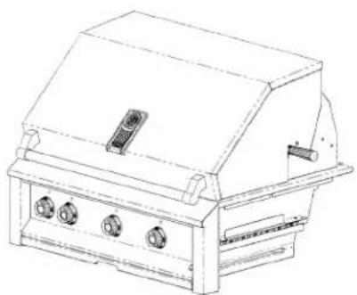
Line drawing of a portable electric stove or grill with three buttons and a lid (no text or symbols)Built-in Model Freestanding Model
natural_image
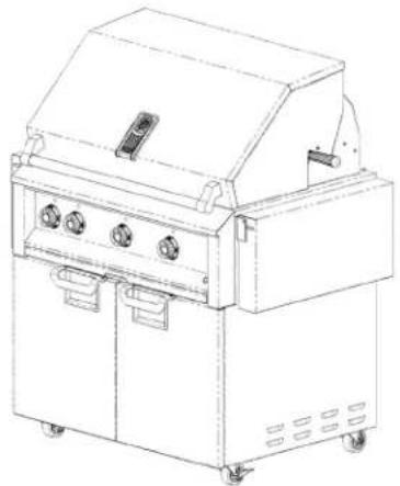
Line drawing of a portable industrial machine with control panel and wheels (no text or symbols)BUILT-IN MODELS
| Model No. Description | |
| EABR30-NG / -LP 30” | BUILT-IN (ALL U-BURNERS w/ ROTISSERIE) |
| EAB30-NG / -LP 30” | BUILT-IN (ALL U-BURNERS) |
| EMBR30-NG / -LP 30” | BUILT-IN (SEAR AND U-BURNERS w/ ROTISSERIE) |
| EMB30-NG / -LP 30” | BUILT-IN (SEAR AND U-BURNERS) |
| EABR36-NG / -LP 36” | BUILT-IN (ALL U-BURNERS w/ ROTISSERIE) |
| EAB36-NG / -LP 36” | BUILT-IN (ALL U-BURNERS) |
| EMBR36-NG / -LP 36” | BUILT-IN (SEAR AND U-BURNERS w/ ROTISSERIE) |
| EMB36-NG / -LP 36” | BUILT-IN (SEAR AND U-BURNERS) |
| EABR42-NG / -LP 42” | BUILT-IN (ALL U-BURNERS w/ ROTISSERIE) |
| EAB42NG / -LP 42” | BUILT-IN (ALL U-BURNERS) |
| EMBR42-NG / -LP 42” | BUILT-IN (SEAR AND U-BURNERS w/ ROTISSERIE) |
| EMB42-NG / -LP 42” | BUILT-IN (SEAR AND U-BURNERS) |
FREESTANDING MODELS
| Model No. Description | |
| EABR30-NG / -LP & ECD30 30" | BUILT-IN (ALL U-BURNERS w/ ROTISSERIE) DOUBLE DOOR CART |
| EAB30-NG / -LP & ECD30 30" | BUILT-IN (ALL U-BURNERS) DOUBLE DOOR CART |
| EMBR30-NG / -LP & ECD30 30" | BUILT-IN (SEAR AND U-BURNERS w/ ROTISSERIE) DOUBLE DOOR CART |
| EMB30-NG / -LP & ECD30 30" | BUILT-IN (SEAR AND U-BURNERS) DOUBLE DOOR CART |
| EABR36-NG / -LP & ECD36 36" | BUILT-IN (ALL U-BURNERS w/ ROTISSERIE) DOUBLE DOOR CART |
| EAB36-NG / -LP & ECD36 36" | BUILT-IN (ALL U-BURNERS) DOUBLE DOOR CART |
| EMBR36-NG / -LP & ECD36 36" | BUILT-IN (SEAR AND U-BURNERS w/ ROTISSERIE) DOUBLE DOOR CART |
| EMB36-NG / -LP & ECD36 36" | BUILT-IN (SEAR AND U-BURNERS) DOUBLE DOOR CART |
| EABR42-NG / -LP & ECD42 42" | BUILT-IN (ALL U-BURNERS w/ ROTISSERIE) DOUBLE DOOR CART |
| EAB42-NG / -LP & ECD42 42" | BUILT-IN (ALL U-BURNERS) DOUBLE DOOR CART |
| EMBR42-NG / -LP & ECD42 42" | BUILT-IN (SEAR AND U-BURNERS w/ ROTISSERIE) DOUBLE DOOR CART |
| EMB42-NG / -LP & ECD42 42" | BUILT-IN (SEAR AND U-BURNERS) DOUBLE DOOR CART |
The rating label contains important information about your appliance such as the model and serial number, gas type and manifold pressure, the BTU rating for each burner type, and the minimum installation clearances.
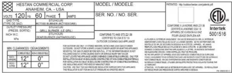
Grill rating label is located on the underside of the drip pan.
PRECAUTIONS - BEFORE YOU USE YOUR GRILL
When properly cared for, your Aspire grill will provide safe, reliable service for many years. However, extreme care must be used since the grill produces intense heat, which can cause serious injury or even death if the instructions are not followed carefully. When using this appliance, basic safety practices must be followed as outlined below.
- NEVER LEAVE THE GRILL UNATTENDED WHILE COOKING.
- Children should not be left alone or unattended in an area where the grill is being used. Never allow them to sit, stand, or play on or around the grill. Do not store items of interest to children around or below the grill or in the cart. Never allow children to crawl inside of the cart.
- Never operate the grill while under the influence of alcohol or drugs.
- Never use the grill in windy conditions. If located in a consistently windy area, oceanfront, mountaintop, etc., a windbreak will be required. Always adhere to the specified clearances as described in the INSTALLATION section of this manual.
- The grill shall be used only outdoors and shall not be used in buildings, garages, sheds, breezeways, or any enclosed areas. Do not operate the grill under unprotected, combustible construction. Use only in well-ventilated areas. See the INSTALLATION section of this manual.
- Do not use the grill unless a leak check has been performed on all gas connections. See the GAS CONNECTIONS section of this manual.
- If the grill is installed by a professional installer or technician, be sure that they show you where your gas supply shut-off is located. All gas lines must have a shut-off that is easily accessible. If you smell gas, check for leaks immediately. Check only with a soap and water solution. Never check gas leaks with an open flame. See the GAS CONNECTIONS section of this manual.
- Check the regulator, hoses, burner ports, air shutter, and venturi / valve section carefully. Always turn off gas at the source (tank or supply line) prior to inspecting parts.
- When lighting a burner, always pay close attention to what you are doing. Be certain you are turning the correct knob labeled for the burner you intend to use. If any burner does not light, or goes out during operation, turn off all gas control knobs, open the hood and wait five (5) minutes before attempting to relight. See the LIGHTING INSTRUCTIONS section of this manual.
- Portable LP cylinders - Always shut off the main valve on the liquid propane (LP) cylinder after each use. Never use a dented or rusted LP cylinder. Never attach or disconnect an LP cylinder, or move or alter gas fittings when the grill is in operation or is hot.
-
Inspect LP gas supply hose prior to each use of the grill. The hose must be kept away from heated areas of the grill. If there is evidence of excessive abrasion or wear, or the hose is cut, it must be replaced before using the grill. The hose and LP regulator are supplied as a complete assembly and must be replaced together. Do not attempt to repair or replace the hose itself. Contact your Hestan dealer for genuine replacement P/N 014309.
-
Keep any electrical supply cord away from the heated areas of the grill. The cord is provided with a 3-prong grounding plug which should not be removed or altered. Do not use this appliance with an ungrounded, 2-prong adapter. The cord must be plugged into a properly grounded GFCI-protected outlet. See INSTALLATION section of this manual.
- Spiders and insects like to nest in the burners, venturis, valves, and orifices of a grill, disrupting the gas flow in the burner. This very dangerous condition can cause a fire behind the control panel, damaging the grill and risking personal injury. If your grill has been unused for a long time, inspect and clean the burners, venturis, valves, and orifices. It is recommended you inspect your grill at least twice a year. See BURNER ADJUSTMENT section of this manual for details.
- Keep the areas surrounding the grill free from combustible materials, trash, or combustible fluids and vapors such as gasoline or charcoal lighter fluid. Do not obstruct the flow of combustion gases (rear) and ventilation airways (front).
- If your grill is mounted on a cart, keep the rear area free and clear of debris, extra LP cylinders, etc. Do not block the ventilation louvers of the cart.
- If your grill is mounted on a cart and stored indoors, ensure that it is cool before moving. If propane is used, the LP cylinder must be disconnected and stored OUTSIDE in a well-ventilated area, out of the reach of children. A grill cover is recommended, even when stored indoors.
- Never move the grill when hot. When in use, portions of the grill are hot enough to cause severe burns.
- Always have an "ABC" type fire extinguisher accessible – never attempt to extinguish a grease fire with water or other liquids.
- Avoid wearing loose-fitting garments or long sleeves while grilling. They could ignite. For personal safety, wear proper apparel while grilling. Some synthetic fabrics are highly flammable and should not be worn while grilling.
- Never let pot holders, grill covers, or other flammable materials come in contact with or too close to any cooking grate, burner, or hot surface until it has cooled down sufficiently. Fabrics may ignite and result in personal injury. Use only dry potholders. Moist or damp potholders on hot surfaces may cause burns from steam. Do not use a towel or bulky cloth in place of potholders. Do not let potholders touch hot portions of the cooking grates or warming racks.
- Never touch the cooking grates, hood, or immediate surrounding metal surfaces with your bare hands while grilling, as these areas become extremely hot and could cause burns. Use only the handles and knobs provided for operation of the grill.
- Protect your hand when opening a hot grill hood. Use an insulated glove or mitt when operating the grill. Always open the hood slowly to allow heat and smoke to escape before fully opening. Keep your face and body as far away as possible when opening the hood. Never lean over an open hot grill.
- The grill hood must be fully opened while lighting the grill. Opening the gas valves on a closed grill before lighting will not make it light sooner or more efficiently. It will only risk explosion and personal injury, or death. Never lean over a hot grill surface, or look directly into the grill when attempting to light. See the LIGHTING INSTRUCTIONS section of this manual.
- Do not heat unopened food containers (cans) as pressure build-up will cause the container to explode.
- Do not use aluminum foil to line cooking grates or the drip tray. This will alter the airflow to the grill or trap excessive heat in the control area. This can melt control knobs, wiring, or igniters, and increase the risk of personal injury. Such damage is specifically excluded from our warranty.
- Never grill without the drip tray in place and pushed all the way to the back of the grill. Without the drip tray, hot grease can leak downward creating a fire or explosion hazard.
- Grease is extremely flammable. Let hot grease cool before attempting to handle or dispose of it. Avoid letting grease deposits collect in the bottom of the grill by cleaning the drip tray often. Never clean while the grill is on, or hot from recent use.
PRECAUTIONS - BEFORE YOU USE YOUR GRILL(continued)
- Grilling excessively fatty meats and oils will cause flare-ups. Internal fires or damage caused by them or by the grill being left unattended, are not covered under the terms and conditions of our warranty.
- Never use charcoal, pellets, wood, or any other solid fuel in the grill. Wood chips for smoking are to be used with the smoker accessory only. See the SMOKER section of this manual.
- Only certain types of glass, heatproof glass-ceramic, earthenware, or other glazed utensils are suitable for grill use. However, these types of materials may break with sudden temperature changes. Use only on low or medium heat settings, and according to their manufacturers' directions.
- Do not lean on side shelves or place a load of more than 25 lbs (11.3 kg) on a side shelf.
- Do not repair or replace any part of the grill unless specifically recommended in this manual. All other warranty and non-warranty service should be referred to and performed by a qualified technician.
- For proper lighting and performance of the burners, keep the ports clean. It is necessary to clean them periodically for optimum performance. The burners will operate only in one position and must be mounted correctly for safe operation. See BURNER ADJUSTMENT section of this manual.
- Clean the grill with caution. Avoid steam burns - do not use a wet sponge or cloth to clean the grill while it is hot. Some cleaners produce noxious fumes or can ignite when applied to a hot surface. Be sure all grill controls are turned off and the grill is cool before using any type of aerosol cleaner on or around the grill. The chemical that produces the spraying action could, in the presence of heat, ignite or cause metal parts to corrode. Clean and perform general maintenance on the grill twice a year. Watch for corrosion, cracks, or insect activity. See the CLEANING AND MAINTENANCE section of this manual.
REGULATORY / CODE REQUIREMENTS
Installation of this cooking appliance must be made in accordance with local codes. In the absence of local codes, this unit should be installed in accordance with the National Fuel Gas Code ANSI Z223.1/NFPA 54, Natural Gas and Propane Installation code CSA B149.1, or Propane Storage and Handling Code B149.2.
All Electrical Components must be electrically grounded in accordance with local codes or in the absence of local codes with the National Electrical Code ANSI/NFPA 70, or Canadian Electrical code CSA C22.1.
STATE OF MASSACHUSETTS
Massachusetts requires all gas be installed using a plumber or gas fitter carrying the appropriate Massachusetts license. All permanently installed natural gas or propane installations require a T handle type manual gas valve be installed in the gas supply line to this appliance. This does not apply to portable propane installations using a 20lb. cylinder.
CALIFORNIA PROPOSITION 65 - WARNING
The burning of gas cooking fuel generates toxic by-products, which are on the list of substances which are known by the State of California to cause cancer or reproductive harm. California law requires businesses to warn customers of potential exposure to such substances. To minimize exposure to these substances, always operate this unit according to the use and care manual, ensuring you provide good ventilation when cooking with gas. This warning is issued pursuant to California Health & Safety Code Sec. 25249.6.
Use only a standard 20 lb. (9.1kg) liquid propane (LP) gas cylinder - 12.25" diam. X 18.25" H (31cm X 47cm) which features an Overfill Protection Device. The cylinder must be installed in the upright position. Do not use a dented or rusty LP cylinder as it may be hazardous and should be checked by your LP supplier. Never use a cylinder with a damaged valve. Never move or alter the gas fittings. Check the expiration date on the cylinder collar as well. Do not refill an expired cylinder, it must be replaced. If you buy refilled (exchange) LP cylinders, check this date as well.
PORTABLE LP GAS CYLINDERS (continued)
The LP gas cylinder must be constructed and marked in accordance with the specifications for LP gas cylinders of the U.S. Department of Transportation (DOT). The cylinder must be provided with a shut off valve terminating in an LP gas supply cylinder valve outlet specified, as applicable, for connection type QCC1 in the standard for compressed gas cylinder valve outlet and inlet connections ANSI/CGA-V-I.
WARNING
Certain liquid propane dealers may fill LP cylinders for use in the grill beyond cylinder filling capacity. This “overfilling” may create a dangerous condition due to a build-up of excess pressure. As a safety device, there is a pressure relief valve which will vent propane gas vapor to relieve this excess pressure. This vapor is combustible and therefore can be ignited. To reduce this danger, you should take the following safety precautions:
- When you have your cylinder filled, be sure you tell the supplier to fill it to no more than 80% of its total capacity.
- If you own or use a spare cylinder, you should NEVER store it near or under the grill/cart unit or burner box, or near any other ignition or heat source (like a water heater or furnace).
IF THE INFORMATION IN 1 AND 2 ABOVE IS NOT FOLLOWED EXACTLY, A FIRE CAUSING DEATH OR SERIOUS INJURY MAY OCCUR.
-
The LP cylinder must be disconnected and stored OUTSIDE in a well-ventilated area, out of the reach of children.
-
Do not store a full cylinder in direct sunlight.
LOCATING AND ASSEMBLING THE GRILL
When determining a suitable location for your grill, take into account concerns such as exposure to wind, rain, sprinklers, proximity to traffic paths, and keeping any gas supply line runs as short as possible.
Locate the grill only in a well-ventilated area. Never locate the grill in a building, garage, breezeway, shed or other such enclosed areas without an approved ventilation system. Never locate the grill over, under, or next to unprotected combustible construction.
During heavy use, the grill will produce a lot of heat and smoke. The grill is designed to take in cool air at the front control panel area, and send the combustion products and smoke out the exhaust gap at the rear of the hood. It is important to maintain this flow at all times. Using the grill in windy areas can disrupt this proper flow and cause damage to your grill, or result in burn hazards to the user. See Fig. 1 for details.
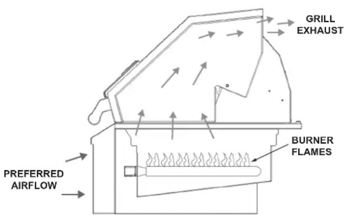
Figure 1
When installing a grill or other gas appliance into an enclosure (island), the enclosure must be constructed with ventilation openings to avoid accumulation of gas should there be a leak. See the INSTALLATION section of this manual for details.
Ensure all packaging, straps, etc. have been removed from the grill. Remove any tie-down wires from the burners.
Your Aspire grill has provision for mounting onto a mobile cart if you choose to do so. Contact your Hestan dealer for the appropriate cart for your grill. If your grill is mounted on a cart, engage the brakes on the casters to prevent movement of the cart.
©2017 Hestan Commercial Corporation

LOCATING AND ASSEMBLING THE GRILL (continued)
Ensure that the burners are positioned correctly on their orifices, and are fully seated onto their rear hanger brackets (see Fig. 2). The burners should not move side-to-side or front-to-back if properly seated.
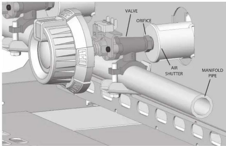
Figure 2
Above each U-burner is a stainless steel radiant tray containing specially shaped ceramic briquettes. Position the radiant trays onto the lower ledge of the burner box in the grill, and then install the cooking grates on the upper ledge (see Fig. 3). The burners and radiant trays work together to create a very even heat, front-to-back, left-to-right. The radiant trays also serve to minimize flare-ups, and prevent blockages of the burner ports from falling grease and debris. The radiant trays and U-burners must be used together and are integral to the performance of the grill. Do not cook on the grill without them.
Note: Infrared Sear Burners do not require the radiant trays. NEVER place a radiant tray over a Sear Burner.
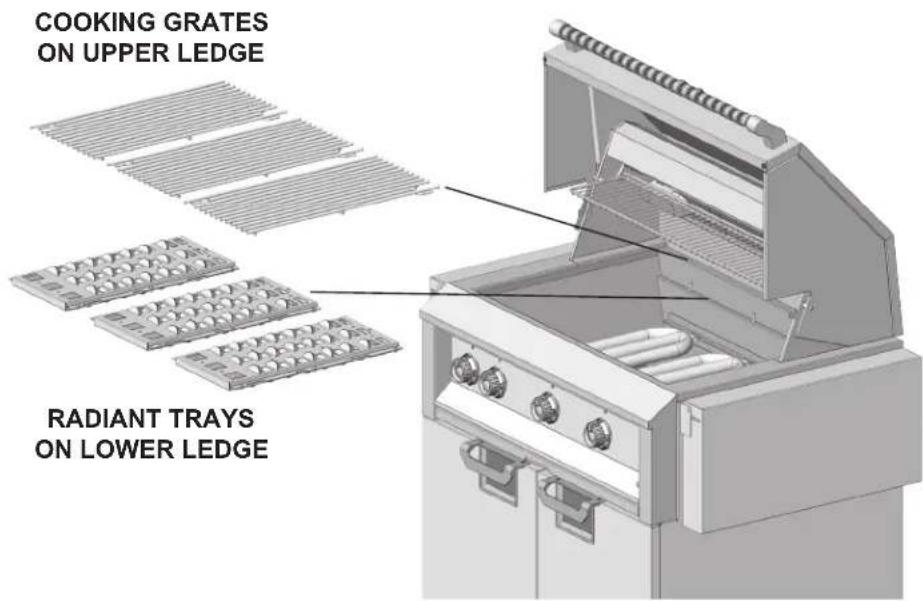
Figure 3
CLEARANCES
TO NON-COMBUSTIBLE CONSTRUCTION
A minimum of 4" (10 cm) clearance from the back of the grill to non-combustible construction is required to allow the hood to be opened fully.
TO COMBUSTIBLE CONSTRUCTION
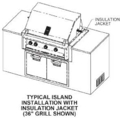
This appliance should NOT be installed over, under or next to unprotected combustible construction. If your enclosure (island) is combustible, then an insulated jacket manufactured by Hestan is required. See INSULATED JACKET dimensions below to make allowances in your enclosure for this item. A minimum clearance to vertical combustible material is 12" (30 cm) on the sides and the rear of the appliance.
WARNING
The minimum vertical clearance to combustible materials means that ALL combustible materials must be outside this 12" (30 cm) zone. As an example, if you have an island with a stucco or tiled surface and wood-frame construction beneath, the wood is considered combustible, even though the grill is touching the stucco or tile surface, which is non-combustible. In extreme circumstances, the wood could potentially get hot enough to burn.
VENTILATION OPENINGS
A minimum of three 10 in ^2 (65 cm ^2 ) of ventilation openings must be provided for both left and right sides of your enclosure (island), as well as the back. These openings are required to safely dissipate gas vapors if there is a leak in your enclosure.
BUILT-IN DIMENSIONS
![2 OPENINGS FOR GAS & ELECTRICAL W 5.5 MIN. [14] H 36.0 [91.4] REF. 19.0 [48.3] 2.5 [6.4] MIN. 10 in² [64.5 cm²] MIN. VENTILATION OPENING ON BOTH SIDES AND REAR OPENING FOR ACCESS DOORS](/content/2026/04/741279/images/4dafa3c058487644dc345b02203f1ddba179b404c6c0ab0b6f435a11297ea3e0.jpg)
DIMENSIONS IN [ ] ARE IN CM.
LAYOUT FOR NON-COMBUSTIBLE ENCLOSURE (ISLAND)
| GRILL MODEL | W | D | H | |||
| (in) | (cm) | (in) | (cm) | (in) | (cm) | |
| 30" GRILL | 29.0 | 73.7 | 23.5 | 59.7 | 11.5 | 29.2 |
| 36" GRILL | 35.0 | 88.9 | 23.5 | 59.7 | 11.5 | 29.2 |
| 42" GRILL | 41.0 | 104.1 | 23.5 | 59.7 | 11.5 | 29.2 |
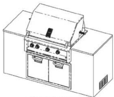
natural_image
Line drawing of a portable stove or oven unit with control panel and door (no text or symbols)TYPICAL ISLAND INSTALLATION (36" GRILL SHOWN)
![3.5" [8.9] SQUARE OPENING FOR GAS SUPPLY 3.5" [8.9] SQUARE OPENING FOR ELECTRICAL 1.2 [3] 1.5 [3.8] .8 [2.1] D TOP VIEW 1.00 [2.5] MAX. COUNTERTOP OVERHANG .56 [1.4] NOTCH](/content/2026/04/741279/images/58b1228b140ba1a49de74cf80527be66ff46ebb9ea6aab10aaca2cd3e6250e0a.jpg)
©2017 Hestan Commercial Corporation
EN
![2 OPENINGS FOR GAS & ELECTRICAL W 3.9 MIN. [9.8] H 19.0 [48.3] 2.5 [6.4] MIN. OPENING FOR ACCESS DOORS 36.0 [91.4] REF. 10 in² (64.5 cm²) MIN. VENTILATION OPENING ON BOTH SIDES AND REAR](/content/2026/04/741279/images/cea51194cca147bd2f2ede4e184dcf68e4e28f7991943c2b6d14280c27d76ddd.jpg)
LAYOUT FOR COMBUSTIBLE ENCLOSURE (ISLAND) WITH INSULATION JACKET
| GRILL MODEL | W | D | H | INSULATION JACKET P/N | |||
| (in) | (cm) | (in) | (cm) | (in) | (cm) | ||
| 30" GRILL | 35.0 | 88.9 | 25.1 | 63.8 | 12.8 | 32.5 | AGU30 |
| 36" GRILL | 41.0 | 104.1 | 25.1 | 63.8 | 12.8 | 32.5 | AGU36 |
| 42" GRILL | 47.0 | 119.4 | 25.1 | 63.8 | 12.8 | 32.5 | AGU42 |
DIMENSIONS IN [ ] ARE IN CM.
![3.5" [8.9] SQUARE OPENING FOR GAS SUPPLY 1.5 [3.8] 3.5" [8.9] SQUARE OPENING FOR ELECTRICAL 4.2 [10.6] 3.1 [7.9] D 3.8 [9.7] TOP VIEW TYPICAL INSTALLATION INSULATION (36" GRILL) 1.0 [2.5] MAX. COUNTERTOP OVERHANG](/content/2026/04/741279/images/8660dff785274fc27777c6902848a34a475c4baa4bed7d1f61ec1c37f9c5bd4c.jpg)
![120VAC - 15AMP GFCI PROTECTED OUTLET 36.0 [91.4] REF. 10" x 11" [25 x 28] ELECTRICAL BOX LOCATED ON INSIDE REAR WALL OF ENCLOSURE 8.0 MIN. [20.3] 10 in² [64.5 cm²] MIN. VENTILATION OPENING ON BOTH SIDES AND REAR FRONT VIEW](/content/2026/04/741279/images/45701d31c489fb272a6426859ba3fa1db1318a8b3586ba8033e4c90d7a6086a2.jpg)
SUPPLEMENTARY VENTILATION
In certain installations, such as an island up against a house or other structure, or perhaps a short roof overhang above your grill; a “range-hood” style ventilation unit may be desirable to direct smoke and grease away from those structures. In these cases, Aspire by Hestan recommends you consult with your outdoor kitchen designer/contractor for more information on choosing the appropriate ventilation solution.
![DUCT 4" - 6" [10 - 15] 30" [1.4] REF. 36" [91.4] REF. DIMENSIONS IN [ ] ARE IN CM.](/content/2026/04/741279/images/918fcfc5e42f7d0a275302fa925304600d79499386e537bfbc083cd32b4cf551.jpg)
GAS SUPPLY
The local gas authority or supplier should be consulted at the installation planning stage in order to establish the availability of an adequate supply of gas (NG or LP). If it is a new installation, have the gas authorities or supplier check the meter size and piping to assure that the unit is supplied with the necessary amount of gas supply and pressure to operate the unit(s).
Gas connections should be made by a qualified plumber, or your professional outdoor appliance installer.
All fixed (non-mobile) appliances must be fitted with an accessible upstream gas shutoff valve as a means of isolating the appliance for emergency shut off and for servicing.
Make certain new piping and connections have been made in a clean manner and have been purged so that piping compound, chips, etc. will not clog regulators, valves, orifices, or burners. Use pipe joint compound / thread sealant approved for natural and LP gases.
NEVER CONNECT THE GRILL TO AN UNREGULATED GAS SUPPLY. Before proceeding, ensure the appliance is fitted for Natural or Liquid Propane gas. Connecting to an improper gas type will result in poor performance and increased risk of damage or injury. Gas type and gas consumption (BTU per hour) for each burner type is shown on the rating label affixed to the underside of the drip tray.
Installation of this cooking appliance must be made in accordance with local codes. In the absence of local codes, this unit should be installed in accordance with the National Fuel Gas Code No. Z223.1/NFPA 54, Natural Gas and Propane Installation code CSA B149-1, or Propane Storage and Handling Code B149.2.
NOTE: See rating label for manifold pressure for the type of gas of your appliance.
CONVERSION KITS
Gas conversion kits are available from your Hestan dealer should you need to convert an LP unit to NG, or vice-versa.
HIGH ALTITUDE KITS
If you live in a high altitude area, 2,000 ft. (610 m) or more above sea level, your grill will require different orifices for proper combustion and performance. High altitude kits are available through Hestan Customer Service. Please have your model and serial number information ready when you call.
NOTE: To ensure proper heating performance of this appliance, verify that the gas line supply pressure is adequate (7.0" WC (1.74kPa) supply pressure is preferred) to maintain 4.0" WC (1.00 kPa) outlet (manifold) pressure. Use only the gas pressure regulator supplied with this appliance. Use a minimum 1/2" ID flex hose to prevent gas starvation. Ensure that the service pipe supplying the grill is fitted with a shut-off valve conveniently positioned and easily accessible as an emergency gas shut-off.

Your Aspire grill for use with Natural Gas is supplied with its own regulator which MUST be installed. If this regulator needs to be replaced, use only the type specified by Hestan for this appliance.
To connect the regulator / hose assembly follow the next steps:
- Locate the regulator and gas connection point in the rear right side of your grill (in cart-mounted models, remove the rear panel to gain access).
- Install the natural gas regulator as shown. Connect gas supply using a minimum 1/2" diameter flexible (semi-rigid) stainless steel gas hose, no more than 48" (1.22m) in length. The hose as well as the connectors must comply with the Standard for Connectors for Outdoor Gas Appliances and Manufactured Homes, ANSI Z21.75 • CSA 6.27, and suitable for outdoor installation. Use the appropriate thread sealant on all connections.
- Proceed to LEAK TESTING section.
GAS CONNECTION - LIQUID PROPANE (LP) CYLINDER
Your Aspire grill for use with LP gas is supplied with a two-stage regulator/hose assembly for connection to a standard 20 lb. LP gas cylinder. This assembly must be used WITHOUT alteration. If this assembly needs to be replaced, contact your Hestan dealer for genuine replacement P/N 014309.
NOTE: To ensure proper heating performance of this appliance, verify that the supply pressure is adequate. Use only the gas pressure regulator supplied with this appliance. This regulator is set to maintain 10 inch WC (2.49 kPa) outlet (manifold) pressure.

To connect the regulator / hose assembly follow these steps:
- Locate the regulator and gas connection point in the rear right side of your grill (in cart-mounted models, remove the rear panel to gain access).
- Connect the 3/8" Flare (compression flare fitting) X 1/2" NPT female adapter to the grill manifold pipe as shown. Connect the regulator/hose assembly to the adapter.
- Connect the regulator/hose assembly to a standard 20 lb. LP cylinder. The hose as well as the connectors must comply with the Standard for Connectors for Outdoor Gas Appliances and Manufactured Homes, ANSI Z21.75 • CSA 6.27, and suitable for outdoor installation. Use the appropriate thread sealant on all thread connections.
- Proceed to LEAK TESTING section.
GAS CONNECTION - LP PIPED SYSTEMS
An LP piped system is one with a large central LP tank that feeds an entire household. These systems are normally equipped with a high pressure regulator by the large LP tank, and low pressure regulators close to the home. The gas line connectors must comply with the Standard for Connectors for Outdoor Gas Appliances and Manufactured Homes, ANSI Z21.75 • CSA 6.27, and suitable for outdoor installation. The connection shall be 48" (1.22 m) or less.
Please contact Hestan Customer Service to order an LP Piped System Kit for this unique installation. Specify if you have a NG or LP grill when ordering the kit.
NOTE: To ensure proper heating performance of this appliance, verify that the gas line supply pressure is adequate. The regulator must be set for a supply pressure of 11 inch WC (2.74 kPa) to maintain 10 inch WC (2.49 kPa) outlet (manifold) pressure. Use only the gas pressure regulator supplied with this appliance. Use a minimum 1/2" ID flex hose to prevent gas starvation. Ensure that the service pipe supplying the grill is fitted with a shut-off valve conveniently positioned and easily accessible as an emergency gas shut-off.
LP TANK RESTRAINT
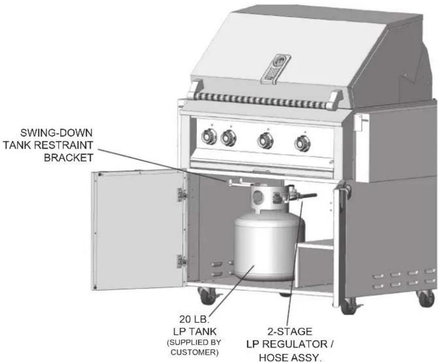
If you purchased a Aspire Grill on a cart, be sure to locate the LP cylinder in the opening in the floor of the cart. It is important the tank does not fall over or stretch the hose which could cause a gas leak. Use the swing-down tank restraint bracket located on the left interior wall of the cart.
LEAK TESTING
GENERAL
Although all gas connections on your grill are leak tested at the factory prior to shipment, a complete gas tightness check must be performed at the installation site due to possible movement in shipment, or excessive pressure unknowingly being applied to parts of the unit. Periodically check the whole system for leaks, or immediately check if the smell of gas is detected.
BEFORE TESTING
- Do not smoke while leak testing.
- Never leak test with an open flame.
• Make a soap solution of one part liquid detergent and one part water for leak testing purposes. - Apply the solution to the gas fittings by using a spray bottle or a brush.
- For LP units, always check with a full LP cylinder.
TO TEST
- Make sure all control valves are in the "OFF" position.
- Apply the soap solution described above to all fittings.
- Turn the gas supply on.
- Check all connections from the supply line, or LP cylinder up to and including the manifold pipe assembly.
- Soap bubbles will appear where a leak is present. If a leak is present, immediately turn off gas supply, tighten any leaking fittings, turn the gas supply back on, and recheck.
- If you cannot stop a gas leak, turn off the gas supply and call the dealer where you purchased your grill.
- Do not use the grill until all connections have been checked and do not leak.
IMPORTANT NOTE - ALWAYS CHECK FOR LEAKS AFTER EVERY LP CYLINDER CHANGE.
If a leak is present, or if there is evidence of excessive abrasion or wear, or the hose is cut, it must be replaced before using the grill. The hose and LP regulator are supplied as a complete assembly and must be replaced together. Do not attempt to repair or replace the hose itself. Contact your Hestan dealer for genuine replacement P/N 014309.
Check all gas supply fittings for leaks before each use. It is handy to keep a spray bottle of soapy water near the shut-off valve of the gas supply line. Spray all the fittings. Bubbles indicate leaks.
BURNER ADJUSTMENTS
Aspire grills feature U-burners, and infrared Rotisserie and Sear Burners. The following instructions apply only to the U-burner.
U-BURNER FLAME ADJUSTMENT
Each grill burner is tested and adjusted at the factory prior to shipment. The proper orifice for the gas type, and the air-fuel (air shutter) adjustment was made at this time. However, variations in the local gas supply, the elevation where you live, converting from one gas type to another, and other factors might make it necessary to adjust the burner flames.
The flames of the burners should be visually checked and compared with the figures below.
Flames should be blue and stable with no yellow tips (LP units will have some yellow tipping). There should be no excessive noise or flame lifting. If any of these conditions exist, remove the burners and check if dirt, debris, spider webs, etc., are blocking the air shutter or burner ports. Proceed with air shutter adjustment if necessary.

GAS CONNECTIONS (continued)
BURNER REMOVAL BEFORE AIR SHUTTER ADJUSTMENT
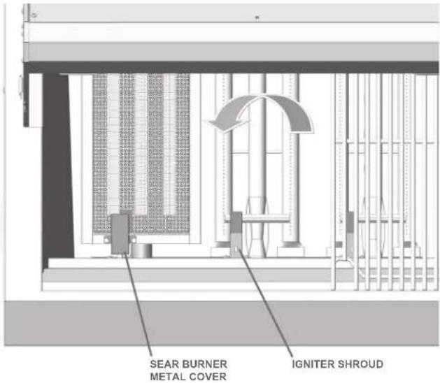
Open your grill and remove the grates, radiant trays, and burners from the firebox area. U-burners are removed by lifting up the rear of the burner, and carefully twisting to clear the igniter shroud. Sear burners have a small metal cover over the igniter which must be removed first. There is also a screw at the rear firebox wall which must be removed. The sear burner can then be carefully removed using the same twisting action to avoid breaking the ceramic igniter.
AIR SHUTTER ADJUSTMENT
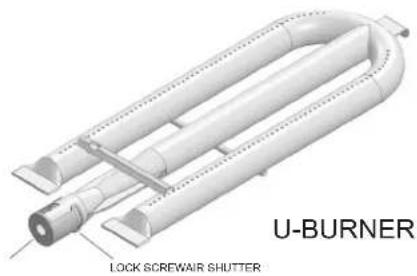
Remove the control panel to gain access to the orifice area and air shutters on the burners. A metal cap at the inlet of the burner called the "AIR SHUTTER" regulates the amount of air that enters into the burner for combustion (see Fig. 4). The air shutter has a lock screw which must be loosened prior to adjustment. Remove the burner carefully from the grill. With a marker pen, mark the current location of the shutter opening, then loosen the screw of the air shutter. Reinstall the burner. Make certain that the burners are sitting properly on the orifices taking care not to move or damage the igniter electrodes. Reinstall the radiant trays.
natural_image
3D rendering of a U-Burner lock screw shutter assembly (no text or symbols on the diagram itself)Figure 4
Light the burner and adjust as follows:
- Turn the valve on "HIGH", light the burner and allow it to warm up for 10 minutes. Be careful because the burner will be hot from this point forward.
- If the flame is yellow, indicating insufficient air, turn the air shutter counter-clockwise to allow more air to the burner.
- If the flame is noisy and tends to lift away from the burner ports, indicating too much air, turn the air shutter clockwise to reduce the amount of air to the burner.
• Once you have established a good flame, make a new mark with the marker pen. - Remove the burner again and retighten the lock screw of the air shutter taking note of your newly marked position.
• Repeat this process for each burner.
• Perform one last check that all burners are properly seated on their orifices and rear hanger bracket.
• Reinstall all radiant trays and cooking grates.
• Reinstall the control panel and control knobs.
VALVE ADJUSTMENTS
The valves on your Aspire grill are preset at the factory for optimum performance. However, the low setting on these valves are adjustable if altitude, low-heat performance, converting from one gas to another, or other factors indicate an adjustment is needed. It is not recommended to adjust the Rotisserie or Sear Burner valves.
WARNING
NEVER ADJUST THE BURNER SO LOW THAT IT MAY GO OUT DURING USE. DO NOT OPERATE THE GRILL WITH THE LOW HEAT SCREW REMOVED. GAS CAN ESCAPE AND CAUSE A POTENTIALLY HAZARDOUS CONDITION.
ADJUSTMENT STEPS
-
Remove the control knobs, drip tray, and control panel from the unit.
-
Follow lighting instructions by setting the control knob on "HI" and allow the burner to preheat for 10 minutes.
-
Turn the control knob to "LOW" and wait for the burner temperature to drop and stabilize, about 10 minutes. Attempting adjustment at any setting other than LOW can create a dangerous condition.
-
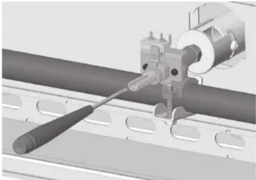
Insert a small flat-blade screwdriver into the valve stem to begin the adjustment (see Fig. 5). The screw only has 2-3 complete revolutions of adjustment. After this, the screw may continue to turn, but is actually coming out of the valve and could result in a gas leak. DO NOT turn more than 3 revolutions!
natural_image
Mechanical assembly diagram showing a tool interacting with a cylindrical component on a conveyor belt (no text or symbols visible)Figure 5
-
Turn counter-clockwise very slowly to INCREASE the low flame. The flame will take a few seconds to respond to the adjustments you are making.
-
Adjust the flame so the burner is still fully lit on all ports, without fluttering or going out. Turn off the burner and re-light. Check the new low setting once again to assure proper adjustment is reached. Reattach the control knob.
INFRARED BURNER FLAME ADJUSTMENT
Infrared burners do not require adjustment and need only be checked visually for proper performance. On HIGH, an infrared burner should glow red evenly over its entire surface. A diminished red glow and/or a large blue "halo" of flame on the surface of the infrared burner indicates improper airflow or a blockage at the burner itself. Call for service.
ELECTRICAL SUPPLY
Important: This appliance must be electrically grounded in accordance with local codes, or in the absence of local codes with the National Electrical Code, ANSI/NFPA 70-1990.
WARNING
Appliances equipped with a flexible electrical supply cord are provided with a three-prong grounding plug. It is imperative that this plug be connected to a properly grounded three-prong receptacle. If the receptacle is not the proper grounding type, contact an electrician. Do not remove the grounding prong from this plug.
The grill is designed for 120 volt AC power and must be plugged into a Ground Fault Circuit Interrupter (GFCI) protected circuit. Do not connect the grill to the electrical supply until after gas connections have been made and leak checks have been performed.
ELECTRICAL SUPPLY(continued)
KEEP ANY ELECTRICAL CORD AND FUEL SUPPLY HOSE AWAY FROM ANY HEATED SURFACES.
- To protect against electric shock, do not immerse cord or plugs in water or other liquid.
- Unplug from the outlet when not in use and before cleaning. Allow to cool before putting on or taking off parts.
- Do not operate any outdoor cooking gas appliance with a damaged cord or plug, or after the appliance malfunctions or has been damaged in any manner. Contact the manufacturer for repair.
- Do not let the cord hang over the edge of a table or touch hot surfaces.
- Do not use an outdoor cooking gas appliance for purposes other than intended.
- Use only a Ground Fault Circuit Interrupter (GFCI) protected circuit with this outdoor cooking gas appliance.
- Never remove the grounding prong or use with a 2-prong ground adapter.
- Use only extension cords with a 3-prong grounding plug, rated for the power of the equipment, and approved for outdoor use with a W-A marking.
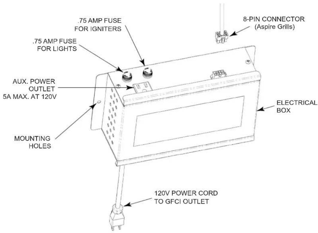
ELECTRICAL BOX
IMPORTANT - READ ALL INSTRUCTIONS BEFORE YOU BEGIN
Some parts have sharp edges. Care must be taken when handling the various components to avoid personal injury. Wear gloves when handling.
- If you are installing your grill in a cart, please consult the instruction manual that came with your cart. If you are installing your grill in an enclosure (see image below), you should locate the electrical box on the inside rear wall below the grill, or in a convenient location to access the box for service, or to replace a fuse. Leave some slack in the cables between the grill and box so as not to stretch the wires and make disconnection easier for service.
- The electrical box has 2 mounting holes on either side to attach to a wall or other structure (mounting hardware not included). The box should be approx. 8" (20cm) above the ground to avoid water intrusion under your island. See the INSTALLATION section of this manual for details.
- Once mounted, connect the white connectors from your grill to the appropriate receptacles on top of the electrical box. The grill is designed for 120 volt AC power and must be plugged into a Ground Fault Circuit Interrupter (GFCI) protected circuit. Do not connect the grill to the electrical supply until after gas connections have been made and leak checks have been performed.
KEEP ANY ELECTRICAL CORD AND FUEL SUPPLY HOSE AWAY FROM ANY HEATED SURFACES.
![120VAC - 15AMP GFCI PROTECTED OUTLET 36.0 [91.4] REF. 10" x 11" [25 x 28] ELECTRICAL BOX LOCATED ON INSIDE REAR WALL OF ENCLOSURE 8.0 MIN. [20.3] 10 in² [64.5 cm²] MIN. VENTILATION OPENING ON BOTH SIDES AND REAR FRONT VIEW](/content/2026/04/741279/images/3074e8d0b2dd386c0d8cc78e84eaf3298c865db1c478693719bf1fc8851a3cf1.jpg)
LIGHTING INSTRUCTIONS
Aspire grills feature hot-surface igniters for all U-burners, and infrared Rotisserie and Sear Burners. YOU MUST HOLD IN THE KNOB to make the hot-surface igniters light the burners.
All burners can be manually lit should that become necessary.
CONTROL KNOB LAYOUT
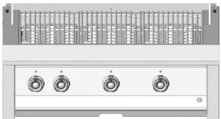
Seen here is a typical layout (36" model shown, Fig. 6) for the control knobs. The rotisserie control is always to the far left side. Control panel LED light switch is on the far right.
The lighting instructions for all burners are visible when you pull out the drip tray.
natural_image
Front view of a server rack with four rotary switches (no text or labels visible)Figure 6
LIGHTING GRILL BURNERS (U-burner or Sear Burner)
- Read Use & Care Manual before lighting. Open lid during lighting. Stand as far away as possible when lighting.
- Push & hold selected knob for 5 seconds, then turn to "HIGH". Burner should light. Once lit, adjust flame as needed.
- If burner does not light in 5 seconds, turn knob to "OFF" and wait 5 minutes before re-lighting.
- If burner fails to light, see USE & CARE MANUAL for match lighting instructions.
LIGHTING ROTISSERIE BURNER
- Push & hold the knob for 5 seconds, then turn to the "HIGH". Continue to hold in the knob for at least 30 seconds after lighting. Rotisserie burner should stay lit and begin to glow. Release the knob, burner should stay on.
- If burner does not stay lit, turn knob to "OFF" and wait 5 minutes before re-lighting.
- If burner fails to light, see USE & CARE MANUAL for match lighting instructions.
MATCH LIGHTING INSTRUCTIONS
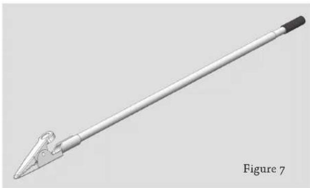
If a burner will not light after several attempts, it can be lit with a match. Open the hood and allow 5 minutes for any accumulated gas to dissipate from the grill. Use a long-stem fireplace match, or attach a short match to the match lighting clip provided with your Aspire Grill (see Fig. 7).
When attempting to light a burner with a match, be sure you selected the correct control knob for that burner. Keep your face away as far as possible, and pass the lit match through the openings of the
natural_image
3D rendered image of a long, metallic tool or rod with a pointed tip and black base, labeled 'Figure 7' (no text on the object itself)cooking grates and radiant trays and position near the burner ports. Push and turn the control knob to "HIGH" until the burner lights. Repeat this procedure for each burner if necessary. If the burner does not light in 5 seconds, turn the control knob to "OFF" and wait 5 minutes before trying again. If the burner will not light after several attempts, see the TROUBLESHOOTING section of this manual.
In sunny locations, infrared Rotisserie and Sear Burners may be difficult to see if they are lit. After attempting to light, you can very carefully wave your hand 8-10 inches (20-25 cm) away from the burner surface to feel the heat of the burner. If there is no heat, OR IF YOU SMELL GAS, shut off the control knob and wait 5 minutes before attempting to re-light.
Your Aspire Grill is a powerful and versatile cooking tool. Traditional grilling requires high heat for searing and proper browning. Many meats are initially cooked on “HIGH” to sear / brown the meat and lock in juices. After that, the temperature can be lowered to complete the cooking, such as with large pieces of meat or poultry. This method will cook the food through without burning the outside. Traditional barbecuing (foods cooked for a long time at low heat) is also possible with your Aspire Grill. As with any new tool, it will take a little practice to get to know your new grill, how hot it runs, cooking times for your favorite foods, etc. DO NOT leave the grill unattended while cooking.
PREHEATING
A typical preheat time for the U-burner is about 10-15 minutes on “HIGH”. The infrared Rotisserie and Sear Burners also require 10-15 minutes pre-heat time.
TEMPERATURE GAUGE
The large temperature gauge in your Aspire grill hood indicates when your grill is ready for cooking. The dial reads the air temperature in your grill, but is calibrated to approximate the temperature at the cooking surface. (see Fig. 8)
COOKING WITH U-BURNERS AND SEAR BURNERS
The Aspire by Hestan U-burner was designed with even heating in mind. The burners, along with the specially designed valves, allow for a broad range of cooking temperatures. The U-burners can sear and grill your meats on high heat, or be dialed down low for authentic barbecuing. The radiant briquette trays are an integral part of this cooking system. They serve to even out the heat, while also reducing flare-ups and vaporizing drippings which release aromas that are absorbed by the meat.
For those seeking a little more, the extreme heat of an our Infrared Sear Burner offers even more power for those wishing a quick sear to lock in flavor, while still retaining temperature control. However, your grilling times are much shorter. The mesh screen on the burner serves to protect the ceramic tiles from food debris and drippings which might clog the thousands of pores in the tiles. Most drippings and grease will instantly vaporize on contact with the hot screen and tiles.
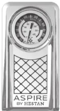
Figure 8
COOKING WITH THE ROTISSERIE
Rotisserie cooking provides an even delivery of heat to your foods. The constant rotation not only cooks foods evenly, it also self-bastes the food as the juices rise to the surface and naturally flow around it. Your foods will be more evenly cooked, more tender, and juicier when slow-roasted on our rotisserie.
Before rotisserie cooking, remove the warming rack from your grill. A roasting pan is provided with your grill to catch excess drippings from clogging your burners below. Be sure you remove it after using your rotisserie and before using the other burners.
The rotisserie system consists of three main parts: the external motor, the spit & forks, and the Infrared Rotisserie Burner.
THE MOTOR
Your Aspire Grill features an externally-mounted, AC motor which can handle a load of 40 in-lbs and a maximum diameter of 10 inches (25 cm). The motor must be connected to AC power for the rotisserie to work. The speed is not adjustable but should provide a respectable speed for the majority of your rotisserie cooking needs.
THE SPIT & FORKS
The rotisserie can handle large food items up to 40 lbs. You should prepare your food items and first mount it on the spit, then mount the forks. Push the pointed end of the spit through the food and center on the spit. Push on one fork and embed into the food, then tighten the thumb screw (use pliers if necessary). Repeat this process for the opposite fork. You should wrap any loose, dangling pieces of food (like wings) with butcher's string (never use nylon or plastic string).
With the food secured to the spit, slowly roll the spit in the palms of your hands to check for balance. It should rotate smoothly. If you find it has a heavy side, adjust where the spit pierces the meat. An unbalanced spit will cause uneven rotation and uneven cooking. It is normal for the spit to flex with large foods during cooking.
Then mount the spit on the grill before lighting the rotisserie infrared burner. Lighting the burner first could result in burning your hands while trying to mount the spit in the grill. Insert the pointed end of the spit into the square drive receiver of the motor, and also rest it on the small hook-cradles on both walls of the grill. Turn on the motor to check the rotation and balance of the food on the spit. Make adjustments as needed.
THE ROTISSERIE BURNER
The Infrared Rotisserie Burner features a safety valve that automatically shuts off the gas flow any time the burner is not properly lit, such as if it were to go out in windy conditions. The location of the rotisserie burner should be less susceptible to strong wind conditions, but during windy conditions, it's best to keep the hood closed and to periodically check the burner. To light the burner, see the LIGHTING INSTRUCTIONS section of this manual.
NOTICE: Avoid directing water on the Rotisserie Burner as this may damage the ceramic burner panels. Water damage to your Rotisserie Burner is not covered by the warranty.
NOTE: The grill thermometer should not be used for rotisserie cooking. It is not designed to read direct infrared heat.
WOOD CHIP SMOKER
By using real wood chips in the smoker system of your Aspire grill, you can add extra flavor to all of your grilled foods. The smoker accessory is sold separately by your Hestan dealer.
- Soak the wood chips for at least 30 minutes before you plan to use the smoker. Drain completely.
- Fill the smoker tray with the drained wood chips.
- Place the smoker tray on the cooking grate where the temperature is correct to smolder the chips, not burn them. You do not want the chips to ignite. Smoke should begin in about 20-30 minutes.
- When there is no more smoke, use the removal tool supplied with the smoker tray to carefully remove it from the grill. Allow it to cool completely before attempting to refill the tray with more chips.
CLEANING AND MAINTENANCE
STAINLESS STEEL CARE
Stainless Steel is widely used for catering and residential kitchen equipment because of its strength, its ability to resist corrosion, and its ease of cleaning. Unfortunately, the metal is often taken for granted and it is assumed that no problems will arise during its usage. However, some care is required to ensure a long service life of the grill.
To maintain the original appearance of your Aspire grill, a regular cleaning routine should be carried out using the following guidelines:
- After use, following the safety precautions detailed earlier in this manual, wipe the grill with a soft, damp, soapy cloth and rinse with clean, warm water. This should remove most substances encountered during the grilling process.
- For stubborn stains, including burnt-on grease and food-borne deposits, use a multipurpose, non-abrasive, cream cleanser and apply with a soft damp cloth. Rinse with fresh water, as described above. On no account should steel wool pads be used unless they are made of stainless steel.
- Harsh abrasives and metallic scouring materials should not be used for cleaning stainless steel as they will leave scratch marks in the surface and damage the appearance of the grill. Likewise, do not use wire brushes, scrapers or contaminated scouring pads.
- For those areas with a directional grain, any cleaning with abrasives should be carried out along this grain direction and not across it.
- After use, always remove wet cleaning aids (such as cloths, pads, containers) from the surface, to avoid formation of water marks or stains.
- If required, dry the grill after use with a soft dry cloth or towel.
If the preceding guidelines are adhered to, your Aspire grill should offer excellent life and should live up to its reputation of being “stainless”. Neglect of this practice, however, can lead to deterioration of the surface and, in some extreme cases, corrosion of the steel itself. The two most common types of corrosion that may be encountered, particularly on stainless steel, are rust marks and pitting of the surface.
RUST-BROWN MARKS
These rust marks are likely the result of small particles of “ordinary-steel” which have become attached to the surface and have subsequently rusted in the damp environment. The most common source of such particles is from steel wool scouring pads, but contamination may also occur from carbon steel utensils and old water supply pipes. These brown marks are only superficial stains, which will not harm the grill. They should be removable using a soft damp cloth and a multi-purpose, non-abrasive, cream cleanser. Occasionally, it may be necessary to resort to a proprietary stainless steel cleanser to return the surface of the grill to its original condition. To avoid re-occurrence of any “rust-staining”, it is essential that the source of the contamination is eliminated. An Aspire grill cover will go a long way toward preventing this kind of contamination.
PITTING
A more severe form of corrosion is pitting of the surface. The sources of this corrosive attack can usually be attributed to certain household products such as bleach, household cleaners containing bleach (sodium hypochlorite), and pool chlorine. If you see pitting of the stainless steel surface, you can attempt to buff it out using stainless steel abrasive pads, but in most cases, pitting of the surface cannot be removed.
FOODSTUFFS
In general, stainless steel is fully resistant to all foodstuffs in common use. Only in isolated cases, such as when concentrated salt and vinegar mixtures are allowed to remain in contact with the steel for a prolonged period, can any surface marking result. Clean the surface as per instructions above.
CARE OF PAINTED SURFACES (IF APPLICABLE)
Aspire grills are available in standard stainless steel, or four optional colors. The tough powder-coating on these panels are commonly used on automotive parts, and commercial and residential appliances because of their excellent chip resistance, and resistance to a variety of chemicals. The finish should hold up well outdoors in most conditions. However, like any painted surface, special care must be taken when cleaning this finish.
To clean your powder-coated surface:
- Carefully remove any loose deposits with a wet sponge.
- Use a soft brush (non abrasive) or cloth, and a mild household detergent solution to remove dust, salt and other deposits. Never use any solvent-based cleaners, stainless steel cleaners, heavy degreasers, oven cleaners, etc. on the painted surfaces. They can permanently damage the paint.
- Rinse off with clean fresh water and dry with a clean cloth.
CARE & MAINTENANCE OF GRILL COMPONENTS
GRILL GRATE AND WARMING RACK
The easiest way to clean the cooking grates is immediately after cooking is completed and after turning off the flame. Wear a grill mitt to protect your hand from the heat and steam. Dip a brass bristle grill brush in hot soapy water and scrub the hot grill rack. Dip the brush frequently in the bowl of water. The steam created as water contacts the hot grill, assists the cleaning process by softening any food particles. The food particles will fall through the grates and burn. If the grill is allowed to cool before cleaning, then cleaning will be more difficult.
DRIP TRAY
The drip tray should be cleaned after every usage of the grill. Leaving a dirty drip tray in place will attract insects and rodents. After allowing the grill to cool completely, remove the drip tray by pulling it out of the grill. After cleaning, reinstall the tray.
GRILL BURNERS
The briquette radiant trays should protect the U-burners completely. However, it may become necessary to clean the burners, or to clean the firebox beneath the burners. Before removal, make sure the gas supply is OFF and the control knobs are in the OFF position. Allow the grill to cool completely, then lift off the cooking grates and radiant trays. To remove burners, lift the rear of the burner out of the hanger bracket slightly, then rotate the burner to the left slightly to clear the igniter shroud at the front of the firebox, then move the burner toward the rear of the firebox until it is out. The burner is made out of a high-grade, 300-series stainless steel which can be cleaned with a brass-bristle brush and warm, soapy water. Do not clean the ports with a toothpick or other item which may break off inside the port. Use a paperclip or needle to do this. Stubborn scale can be removed with a metal scraper. Be sure to rinse everything well and shake out any water and debris trapped inside the burner tube.
Great care should be used when re-installing the burner. It must be correctly centered and secured on the orifice before any attempt is made to relight the grill. The rear burner bracket should lie flat and not have any side-to-side movement. See the LOCATING AND ASSEMBLY section of this manual for details on proper burner installation.
ROTISSERIE BURNER CLEANING
It should not be necessary to clean the Rotisserie Burner, unless food debris or juices have sprayed onto the tiles. Should this happen, after removing the food item & spit, turn the burner back on again for an additional 5 minutes to allow the burner to vaporize any residue. Do not attempt to clean the tile ports with a toothpick or other item which may break off inside the port. If needed, you may also wait until the burner has cooled completely and brush the tile faces to remove any accumulated ash.
NOTICE: Avoid directing water on the Rotisserie Burner as this may damage the ceramic burner panels. Water damage to your Rotisserie Burner is not covered by the warranty.
SEAR BURNER CLEANING
When used correctly, it should not be necessary to clean Infrared Sear Burners. The hot screen and tiles vaporize anything that falls on them. However, if food debris or drippings were to fall on an unused (not lit) Sear Burner, you can remove the mesh screen and brush the screen and tiles with a stiff brush.
Be sure to do this only when completely cooled down. DO NOT use a metal scraper on the tiles, or put a lot of pressure on the tile faces as they may crack. Alternatively, you can turn on the sear burner to burn everything off.
NOTICE: Avoid directing water into the Sear Burner as this may fill up the inside of the burner housing with water, not allowing it to burn properly. Water intrusion could also damage the ceramic tiles. Water damage to your Sear Burner is not covered by the warranty.
ORIFICE CLEANING
You will need to remove the burner first. It may also be helpful to remove the control panel to get a better look at the orifice (see Fig. 9). Take note of how far the orifice is tightened onto the valve. With the burner removed, remove the orifice from the valve and shine a flashlight through the opening to ensure there is no blockage. Use a sewing needle to clear any debris. Be extremely careful not to enlarge the hole or break off the needle. Once clean, be sure to carefully thread the orifice onto the valve by hand, then use a wrench or deep socket wrench to tighten it securely to the same position as before. Replace the burner as per previous instruction.
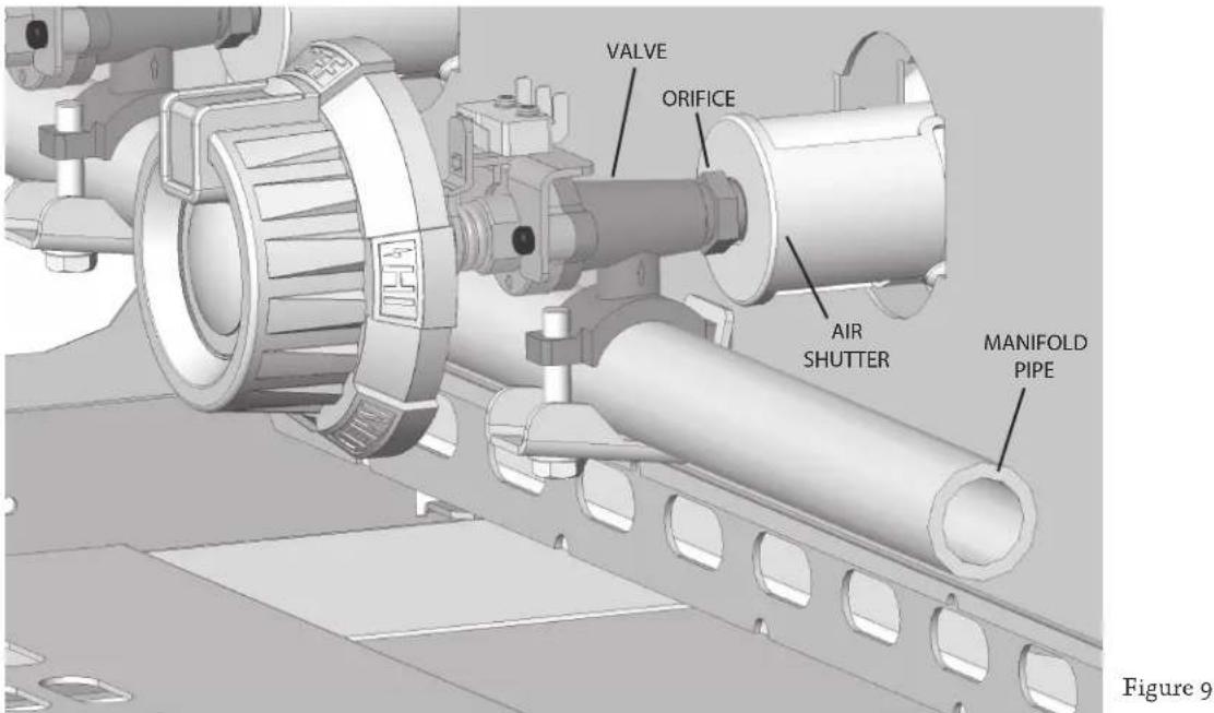
IGNITERS
The hot-surface igniters on your Aspire grill do not require any maintenance and are well protected from debris falling on them.
NOTE: Rough handling of the igniter can crack the ceramic body, causing it to fail. Handle with care.
CLEANING THE BRIQUETTES AND TRAYS
After allowing the grill to cool completely, turn the radiant tray upside-down and operate the grill on high for 30 minutes. The trays are “double sided” and can be left this way to burn off any encrusted food or grease. The trays can occasionally be scrubbed clean with mild soap & water and a plastic bristle brush. Allow them to cool completely, never handle hot trays. Replace the briquette trays, ensuring that they sit level and do not rock. Light all of the burners and check for proper flame characteristics.
natural_image
Exterior view of a modern office building (no signage)Figure 10 Figure 11
natural_image
3D rendering of a mechanical device with a screwdriver and cable (no text or symbols visible)LIGHT BULB REPLACEMENT
- Disconnect the power to your grill before any service or light bulb replacement. Be sure the grill and the lights are completely cool. Halogen lights get extremely hot.
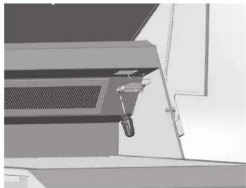
- Open hood and remove the small screw holding the lamp assembly in place (Fig. 10). Remove the lamp assembly, being careful not to drop the glass lens.
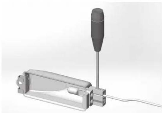
- If needed, use a small flat-blade screwdriver to carefully pry off the lens and set aside. Loosen the 2 screws closest to the lamp housing (Fig. 11). These screws hold the bulb in place. The bulb should come out easily. The bulb is a 20W halogen "Bi-Pin" type, available at most hardware stores & home centers.
- Before installation, it is very important to clean the new bulb carefully with a clean, soft cloth, or tissue paper. Grease, fingerprints, or oils in your skin can leave a residue on the glass surface of the bulb which will create a hot-spot. The bulb will eventually crack at this hot-spot.
- While still using a cloth or tissue paper, install the new bulb in the housing and tighten the screws. Check that the other tiny screws are tight as well.
- Re-install the lens and return the lamp assembly to the hood. Carefully install the screw to secure the assembly to the grill.
ADDITIONAL CONSIDERATIONS
Always keep the area around the grill free of obstructions and debris. Maintain at least 12" (30 cm) of space around the grill to ensure proper airflow, and keep all ventilation openings clear and free of debris. Clean the appliance after each use, and check for blockages, especially at the burner orifices, after periods of prolonged non-use. To maintain the appearance of your Aspire grill for many years, keep it covered when not in use. Backyard environments are harsh on your grills' finish. Long exposure to sun, water, yard chemicals and the elements could diminish the appearance of the stainless steel. This is very evident in ocean-front locations.
Our appliance materials have been tested in saline solutions with higher salinity than seawater. They have also been tested by exposure to highly acidic foods. During and after these tests, we found these materials were able to withstand exposure over prolonged periods of time. However, the above-mentioned corrosive substances, along with neglect, can lead to a situation whereby conditions might combine to cause some damage to occur. Therefore, we suggest that you always keep your grill clean, dry and covered when not in use. This is even more important when long term storage is required. Always store the grill clean, dry and covered with your Aspire grill cover. A dirty grill will attract insects and rodents which is highly unsanitary. In addition, rodents are known to chew on the insulation of wiring which will cause permanent damage to the wiring and possibly electrical components.
For those in desert communities, wind-driven sand is highly abrasive and constant exposure will eventually pit and scratch the surface. Another reason to keep your grill covered when not in use.
| Symptom Check | |
| Burner will not light Not holding in control knob long enough to make igniter glowGas supply not on / shutoff valve closedLP gas cylinder emptyPower cord not plugged in, or no power to receptacle, or blown fuseLow gas pressure to unitBurner ports near igniter are obstructed or dirtyBurner not installed correctly on orificeDefective or clogged burner valveIncorrect orifice or clogged orificeIgniter defective (not glowing)Defective regulator or regulator installed improperly | |
| Burner will not stay lit Burner ports obstructed or dirtyVent plugged on regulator or regulator installed improperlyWindy conditionsLow gas pressure | |
| Slow to heat up Low gas pressure or low LP cylinderBurner ports are obstructed or dirtyDefective or clogged burner valveIncorrect orifice or clogged orifice | |
| Gas Odor Burner went out or did not lightLoose or broken gas lineRuptured pressure regulatorBurner not installed correctly on orificePoor combustion, air-fuel mixture not adjusted properlyObstructed/dirty burner ports | |
| Burner not working well / lazy or yellow flame | Burner ports are obstructed or dirty, check for spider websPoor combustion, air-fuel mixture not adjusted properlyGas pressure incorrect / incorrect regulatorOrifice sized incorrectly for gas type |
| Rotisserie will not light or will not stay lit | Not holding in the control knob long enoughWindy conditionsIgniter defective (not glowing)Power cord not plugged in, or no power to receptacle |
| Interior halogen lights not working | Power cord not plugged in, or no power to receptacleCheck for burned-out bulb or fuse. |
| Control panel LED lights not working | Power cord not plugged in, or no power to receptacleCheck fuse on electrical box. |
| Rotisserie motor not working Power cord not plugged in, or no power to receptacle | |
EN
ELECTRICAL BOX (30, 36 & 42")
EN
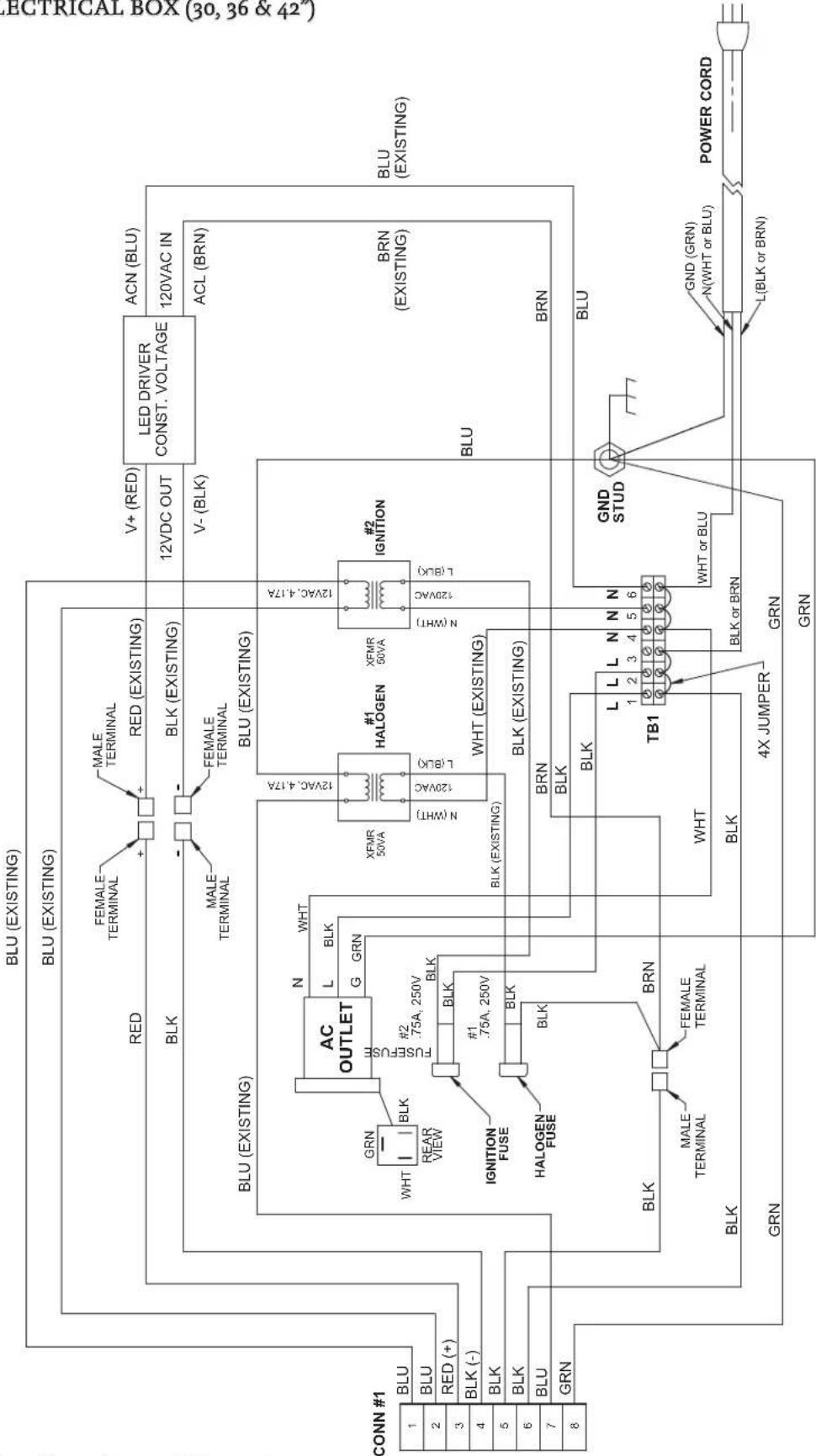
flowchart
graph TD
    A["CONN #1"] --> B["BLU"]
    A --> C["BLU (EXISTING)"]
    A --> D["BLU (EXISTING)"]
    A --> E["BLU (EXISTING)"]
    A --> F["BLU (EXISTING)"]
    A --> G["BLU (EXISTING)"]
    A --> H["BLU (EXISTING)"]
    A --> I["BLU (EXISTING)"]
    A --> J["BLU (EXISTING)"]
    A --> K["BLU (EXISTING)"]
    A --> L["BLU (EXISTING)"]
    A --> M["BLU (EXISTING)"]
    A --> N["BLU (EXISTING)"]
    A --> O["BLU (EXISTING)"]
    A --> P["BLU (EXISTING)"]
    A --> Q["BLU (EXISTING)"]
    A --> R["BLU (EXISTING)"]
    A --> S["BLU (EXISTING)"]
    A --> T["BLU (EXISTING)"]
    A --> U["BLU (EXISTING)"]
    A --> V["BLU (EXISTING)"]
    A --> W["BLU (EXISTING)"]
    A --> X["BLU (EXISTING)"]
    A --> Y["BLU (EXISTING)"]
    A --> Z["BLU (EXISTING)"]
    A --> AA["BLU (EXISTING)"]
    A --> AB["BLU (EXISTING)"]
    A --> AC["BLU (EXISTING)"]
    A --> AD["BLU (EXISTING)"]
    A --> AE["BLU (EXISTING)"]
    A --> AF["BLU (EXISTING)"]
    A --> AG["BLU (EXISTING)"]
    A --> AH["BLU (EXISTING)"]
    A --> AI["BLU (EXISTING)"]
    A --> AJ["BLU (EXISTING)"]
    A --> AK["BLU (EXISTING)"]
    A --> AL["BLU (EXISTING)"]
    A --> AM["BLU (EXISTING)"]
    A --> AN["BLU (EXISTING)"]
    A --> AO["BLU (EXISTING)"]
    A --> AP["BLU (EXISTING)"]
    A --> AQ["BLU (EXISTING)"]
    A --> AR["BLU (EXISTING)"]
    A --> AS["BLU (EXISTING)"]
    A --> AT["BLU (EXISTING)"]
    A --> AU["BLU (EXISTING)"]
    A --> AV["BLU (EXISTING)"]
    A --> AW["BLU (EXISTING)"]
    A --> AX["BLU (EXISTING)"]
    A --> AY["BLU (EXISTING)"]
    A --> AZ["BLU (EXISTING)"]
    A --> BA["BLU (EXISTING)"]
    A --> BB["BLU (EXISTING)"]
    A --> BC["BLU (EXISTING)"]
    A --> BD["BLU (EXISTING)"]
    A --> BE["BLU (EXISTING)"]
    A --> BF["BLU (EXISTING)"]
    A --> BG["BLU (EXISTING)"]
    A --> BH["BLU (EXISTING)"]
    A --> BI["BLU (EXISTING)"]
    A --> BJ["BLU (EXISTING)"]
    A --> BK["BLU (EXISTING)"]
    A --> BLTB["TB1"]
    BLT8["WHT or BLU"] --> TB2TB2TB2TB2TB2TB2TB2TB2TB2TB2TB2TB2TB2TB2TB2TB2TB2TB2TB2TB2TB2TB2TB2TB2TB2TB2TB2TB2TB2TB2TB2TB2TB2TB2TB2TB2TB2TB2TB2TB2TB2TB2TB2TB2TB2TB2TB2TB2TB2TB2TB2TR
    BLT8 --> BLT8
    BLT8 --> BLT8
    BLT8 --> BLT8
    BLT8 --> BLT8
    BLT8 --> BLT8
    BLT8 --> BLT8
    BLT8 --> BLT8
    BLT8 --> BLT8
    BLT8 --> BLT8
    BLT8 --> BLT8
    BLT8 --> BLT8
    BLT8 --> BLT8

    subgraph AC_OUTLET
        B["AC OUTLET"]
        C["FLUT"]
        D["GALOGEN"]
        E["FUSEFUSE"]
        F["GALOGEN FUSE"]
        G["RANK"]
        H["BLK"]
        I["Rear View"]
        J["RANK"]
        K["RANK"]
        L["RANK"]
        M["RANK"]
        N["RANK"]
        O["RANK"]
        P["RANK"]
        Q["RANK"]
        R["RANK"]
        S["RANK"]
        T["RANK"]
        U["RANK"]
        V["RANK"]
        W["RANK"]
        X["RANK"]
        Y["RANK"]
        Z["RANK"]
        AA["RANK"]
        AB["RANK"]
        AC["RANK"]
        AD["RANK"]
        AE["RANK"]
        AF["RANK"]
        AG["RANK"]
        AH["RANK"]
        AI["RANK"]
        AJ["RANK"]
        AK["RANK"]
        AL["RANK"]
        AM["RANK"]
        AN["RANK"]
        AO["RANK"]
        AP["RANK"]
        AQ["RANK"]
        AR["RANK"]
        AS["RANK"]
        AT["RANK"]
        AU["RANK"]
        AV["RANK"]
        AW["RANK"]
        AX["RANK"]
        AY["RANK"]
        AZ["RANK"]
        BA["RANK"]
        BB["RANK"]
        BC["RANK"]
        BD["RANK"]
        BE["RANK"]
        BF["RANK"]
        BG["RANK"]
        BH["RANK"]
        BI["RANK"]
        BJ["RANK"]
        BK["RANK"]
        BL["TB1"]
        BN["TB1"]
        BO["TB1"]
        BP["TB1"]
        BP["TB1"]
        BP["TB1"]
        BP["TB1"]
        BP["TB1"]
        BP["TB1"]
        BP["TB1"]
        BP["TB1"]
        BP["TB1"]
        BP["TB1"]
        BP["TB1"]
        BP["TB1"]
        BP["TB1"]
        BP["TB1"]
        BP["TB1"]
        BP["TB1"]
        BP["TB1"]

    subgraph HALOGEN
        C
        D
        E
        F
        G
        H
        I
        J
        K
        L
        M
        N
        O
        P
        Q
        R
        S
        T
        U
        V
        W
        X
        Y
        Z
        AA
        AB
        AC
        AD
        AE
        AF
        AG
        AH
        AI
        AJ
        AK
        AL
        AM
        AN
        AO
        AP
        AQ
        AR
        AS
        AT
        AU
        AV
        AW
        AX
        AZ
        BA
        BB
        BC
        BD
        BE
        BF
        BG
        BH
        BI
        BJ
        BA
        BB
        BB
        BB
        BB
    end

    subgraph IGNITION
        C
        D
        E
        F
        G
        H
        I
        J
        K
        L
        M
        N
        O
        P
        Q
        R
        S
        T
        U
      end

    subgraph IGNITION_FUSE
            F
            G
            H
            I
            J
            K
            L
            M
            N
            O
            P
            Q
            R
            S
            T
            U
          end

    subgraph IGNITION_FUSE_LA_0.75A_0.75V_0.75V_0.75V_0.75V_0.75V_0.75V_0.75V_0.75V_0.75V_0.75V_0.75V_0.75V_0.75V_0.75V_0.75V_0.75V_0.75V_0.3A_0.3A_0.3A_0.3A_0.3A_0.3A_0.3A_0.3A_0.3A_0.3A_0.3A_0.3A_0.3A_0.3A_0.3A_0.3A_0.3A_0.3A_0.3A_0.3A_0.3C_BRLN_BRLN_BRLN_BRLN_BRLN_BRLN_BRLN_BRLN_BRLN_BRLN_BRLN_BRLN_BRLN_BRLN_BRLN_BRLN_BRLN_BRLN_BRLN_BRLN_BRLN_BRLN_BRLN_BRLN_BRLN_BRLN_BRLN_BRLN_BRLN_BRLN_BRLN_BRLN_BRLN_BRLN_CBDGND(GND)GND(GND)GND(GND)GND(GND)GND(GND)GND(GND)GND(GND)GND(GND)GND(GND)GND(GND)GND(GND)GND(GND)GND(GND)GND(GND)GND(GND)GND(GND)GND(GND)GND(GND)GND(GND)GND(GND)GND(GND)(POWERCORD)
    end

    subgraph Power_Cord_tilde_Rsun & Power_Cord_Solid_Rsun & Power_Cord_Trip_Rsun & Power_Cord_Solid_Rsun & Power_Cord_Trip_Rsun & Power_Cord_Solid_Rsun & Power_Cord_Trip_Rsun & Power_Cord_Solid_Rsun & Power_Cord_Trip_Rsun & Power_Cord_Solid_Rsun & Power_Cord_Trip_Rsun & Power_Cord_Solid_Rsun & Power_Cord_Trip_Rsun & Power_Cord_Solid_Trip_Rsun & Power_Cord_Trip_Rsun & Power_Cord_Solid_Trip_Rsun & Power_Cord_Trip_Rsun & Power_Cord_Solid_Trip_Rsun & Power_Cord_Trip_Rsun & Power_Cord_Solid_Trip_Rsun & Power_Cord_Trip_Rsun & Power_Cord_Solid_Trip_Rsun & Power_Cord_Trip_Rsun & Power_Cord_Solid_TRP_LBLRNLHLHLHLHLHLHLHLHLHLHLHLHLHLHLHLHLHLHLHLHLHLHLHLHLHLHLHLHLHLHLHLHLHLHLHLHLHLHLHLHLHLHLHLHLHLHLHLHLHLHLHLHLHLHLHLHLHLHLHLHLHLHLHLHLHLHLHLHLHLHLHLHLHLHLHLHLHLHLHLHLHLHLHLHLHLHLHLHLHLHLHLHLHLHLHLHLHLHLHLHLHLLMLMLMLMLMLMLMLMLMLMLMLMLMLMLMLMLMLMLMLMLMLMLMLMLMLMLMLMLMLMLMLMLMLMLMLMLMLMLMLMLMLMLMLMLMLMLMLMLMLMLMLMLMLMLMLMLMLMLMLMLMLMLMLMLMLMLMLMLMLMLMLMLMLMLMLMLMLMLMLMLMLMLMLMLMLMLMLMLMLMLMLMLMLMLMLMLMLMLMLMLMAELMELMELMELMELMELMELMELMELMELMELMELMELMELMELMELMELMELMELMELMELMELMELMELMELMELMELMELMELMELMELMELMELMELMELMELMELMELMELMELMELMELMELMELMELMELMELMELMELMELMELMSGLLVLVLVLVLVLVLVLVLVLVLVLVLVLVLVLVLVLVLVLVLVLVLVLVLVLVLVLVLVLVLVLVLVLVLVLVLVLVLVLVLVLVLVLVLVLVLVLVLVLVLVLVLVLVLVLVLVLVLVLVLVLVLVLVLVLVLVLVLVLVLVLVLVLVLVLVLVLVLVLVLVLVLVLVLVLVLVLVLVLVLVLVLVLVLVLVLVLVLVLVLVLLVLLVLLVLLVLLVLLVLLVLLVLLVLLVLLVLLVLLVLLVLLVLLVLLVLLVLLVLLVLLVLLVLLVLLVLLVLLVLLVLLVLLVLLVLLVLLVLLVLLVLLVLLVLLVLLVLLVLLVLLVLLVLLVLLVLLVLLVLLVLLVLLVLLVTTLWTTLWTTLWTTLWTTLWTTLWTTLWTTLWTTLWTTLWTTLWTTLWTTLWTTLWTTLWTTLWTTLWTTLWTTLWTTLWTTLWTTLWTTLWTTLWTTLWTTLWTTLWTTLWTTLWTTLWTTLWTTLWTTLWTTLWITT LWITT LWITT LWITT LWITT LWITT LWITT LWITT LWITT LWITT LWITT LWITT LWITT LWITT LWITT LWITT LWITT LWITT LWITT LWITT LWITT LWITT LWITT LWITT LWITT LWITT LWITT LWITT LWITT LWITT LWITT LWITT LWITT LWITT LWPPTLWPPTLWPPTLWPPTLWPPTLWPPTLWPPTLWPPTLWPPTLWPPTLWPPTLWPPTLWPPTLWPPTLWPPTLWPPTLWPPTLWPPTLWPPTLWPPTLWPPTLWPPTLWPPTLWPPTLWPPTLWPPTLWPPTLWPPTLWPPTLWPPTLWPPTLWPPTLWPPTLWPPTLFPPTLFPPTLFPPTLFPPTLFPPTLFPPTLFPPTLFPPTLFPPTLFPPTLFPPTLFPPTLFPPTLFPPTLFPPTLFPPTLFPPTLFPPTLFPPTLFPPTLFPPTLFPPTLFPPTLFPPTLFPPTLFPPTLFPPTLFPPTLFPPTLFPPTLFPPTLFPPTLFPPTLFPFTLFPFTLFPFTLFPFTLFPFTLFPFTLFPFTLFPFTLFPFTLFPFTLFPFTLFPFTLFPFTLFPFTLFPFTLFPFTLFPFTLFPFTLFPFTLFPFTLFPFTLFPFTLFPFTLFPFTLFPFTLFPFTLFPFTLFPFTLFPFTLFPFTLFPFTLFPFTLFPFTLFPFTTFLPFTTFLPFTTFLPFTTFLPFTTFLPFTTFLPFTTFLPFTTFLPFTTFLPFTTFLPFTTFLPFTTFLPFTTFLPFTTFLPFTTFLPFTTFLPFTTFLPFTTFLPFTTFLPFTTFLPFTTFLPFTTFLPFTTFLPFTTFLPFTTFLPFTTFLPLNTFLPNTFLPNTFLPNTFLPNTFLPNTFLPNTFLPNTFLPNTFLPNTFLPNTFLPNTFLPNTFLPNTFLPNTFLPNTFLPNTFLPNTFLPNTFLPNTFLPNTFLPNTFLPNTFLPNTFLPNTFLPNTFLPNTFLPNTFLPNTFLPNTFLPNTFLPNTFLPNTFLPNTFLPINTFLPINTFLPINTFLPINTFLPINTFLPINTFLPINTFLPINTFLPINTFLPINTFLPINTFLPINTFLPINTFLPINTFLPINTFLPINTFLPINTFLPINTFLPINTFLPINTFLPINTFLPINTFLPINTFLPINTFLPINTFLPINTFLPINTFLPINTFLPINTFLPINTFLPINTFLPINTFLPINTFLPINT FLPPRTTLPPRTTLPPRTTLPPRTTLPPRTTLPPRTTLPPRTTLPPRTTLPPRTTLPPRTTLPPRTTLPPRTTLPPRTTLPPRTTLPPRTTLPPRTTLPPRTTLPPRTTLPPRTTLPPRTTLPPRTTLPPRTTLPPRTTLPPRTTLPPRTTLPPRTTLPPRTTLPPRTTLPPRTTLPPRTTLPPRTTLPPRTTLPPRTTLPPRTTLPPPRTTLPPRTTLPPRTTLPPRTTLPPRTTLPPRTTLPPRTTLPPRTTLPPRTTLPPRTTLPPRTTLPPRTTLPPRTTLPPRTTLPPRTTLPPRTTLPPRTTLPPRTTLPPRTTLPPRTTLPPRTTLPPRTTLPPRTTLPPRTTLPPRTTLPPRTTLPPRTTLPPRTTLPPRTTLPPRTTLPPRTTLPPRTTLPPRTTLPPRTPSLTPSLTPSLTPSLTPSLTPSLTPSLTPSLTPSLTPSLTPSLTPSLTPSLTPSLTPSLTPSLTPSLTPSLTPSLTPSLTPSLTPSLTPSLTPSLTPSLTPSLTPSLTPSLTPSLTPSLTPSLTPSLTPSLTPSLTPSLTPSLTPSLTPSLTPSLTPSLTPSLTPSLTPSLTPSLTPSLTPSLTPSLTPSLTPSLTPSLTPSPLSTPLSTPLSTPLSTPLSTPLSTPLSTPLSTPLSTPLSTPLSTPLSTPLSTPLSTPLSTPLSTPLSTPLSTPLSTPLSTPLSTPLSTPLSTPLSTPLSTPLSTPLSTPLSTPLSTPLSTPLSTPLSTPLSTPLSTPLSTPLSTPLSTPLSTPLSTPLSTPLSTPLSTPLSTPLSTPLSTPLSTPLSTPLSTPLSTPLSTPL STPLSTPLSTPLSTPLSTPLSTPLSTPLSTPLSTPLSTPLSTPLSTPLSTPLSTPLSTPLSTPLSTPLSTPLSTPLSTPLSTPLSTPLSTPLSTPLSTPLSTPLSTPLSTPLSTPLSTPLSTPLSTPLSTPLSTPLSTPLSTPLSTPLSTPLSTPLSTPLSTPLSTPLSTPLSTPLSTPLSTPLSTPLSTPLSTPLSTPLTCLSTPLSTPLSTPLSTPLSTPLSTPLSTPLSTPLSTPLSTPLSTPLSTPLSTPLSTPLSTPLSTPLSTPLSTPLSTPLSTPLSTPLSTPLSTPLSTPLSTPLSTPLSTPLSTPLSTPLSTPLSTPLSTPLSTPLSTPLSTPLSTPLSTPLSTPLSTPLSTPLSTPLSTPLSTPLSTPLSTPLSTPLSTPLSTPLSTPLSTLP STPECTLE 4XJUMPER 4XJUMPER 4XJUMPER 4XJUMPER 4XJUMPER 4XJUMPER 4XJUMPER 4XJUMPER 4XJUMPER 4XJUMPER 4XJUMPER 4XJUMPER 4XJUMPER 4XJUMPER 4XJUMPER 4XJUMPER 4XJUMPER 4X/GRN 4X/GRN 4X/GRN 4X/GRN 4X/GRN 4X/GRN 4X/GRN 4X/GRN 4X/GRN 4X/GRN 4X/GRN 4X/GRN 4X/GRN 4X/GRN 4X/GRN 4X/GRN 4X/GRN 4X /GRN 4X /GRN 4X /GRN 4X /GRN 4X /GRN 4X /GRN 4X /GRN 4X /GRN 4X /GRN 4X /GRN 4X /GRN 4X /GRN 4X /GRN 4X /GRN 4X /GRN 4X /GRN 4X /GRN 6x /GRN 6x /GRN 6x /GRN 6x /GRN 6x /GRN 6x /GRN 6x /GRN 6x /GRN 6x /GRN 6x /GRN 6x /GRN 6x /GRN 6x /GRN 6x /GRN 6x /GRN 6x /GRN 6x /GRN
HARNESS 30" WITHOUT ROTISSERIE
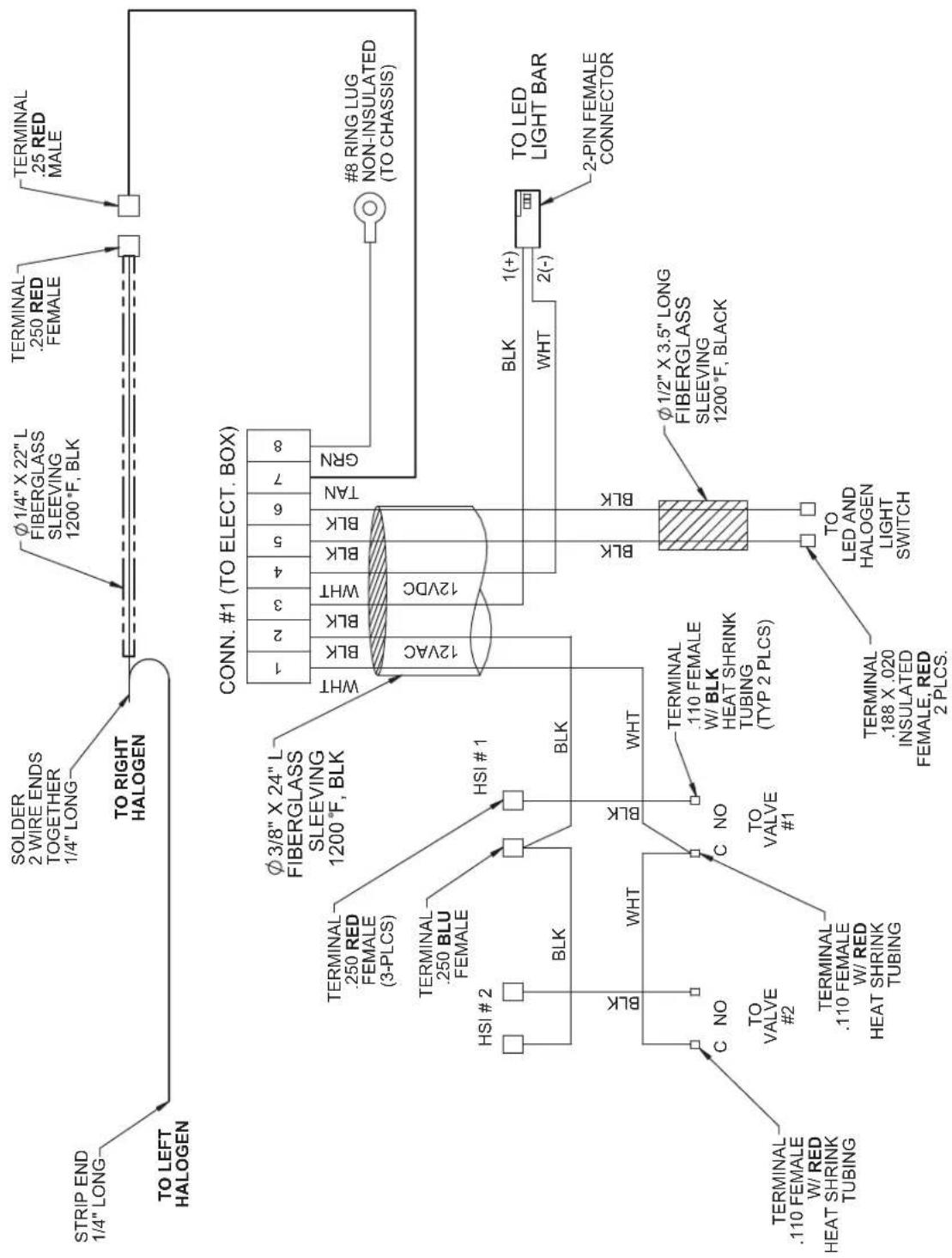
EN
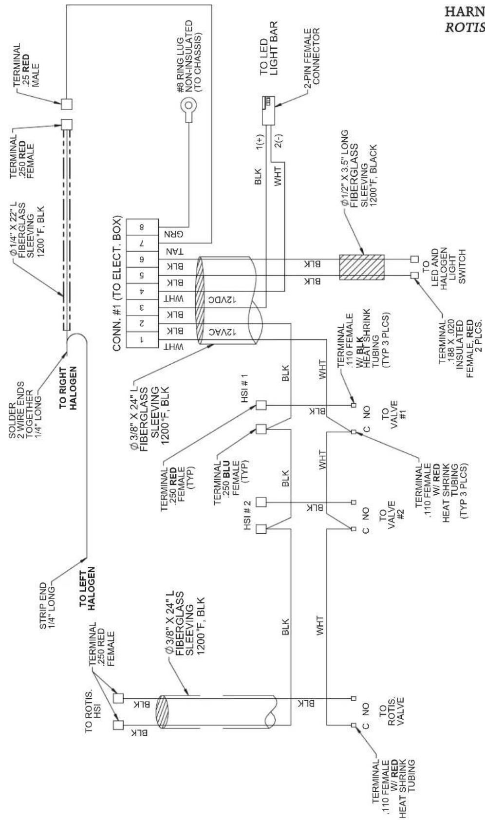
HARNESS 30" WITH ROTISSERIE
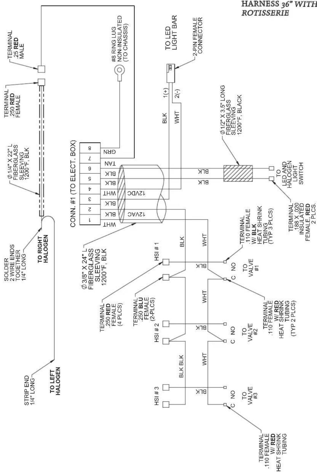
flowchart
graph TD
A["STRIP END 1/4" LONG"] --> B["TO LEFT HALOGEN"]
B --> C["SOLDER 2 WIRE ENDS TOGETHER 1/4" LONG"]
C --> D["TO RIGHT HALOGEN"]
D --> E["Φ 1/4" X 22" L FIBERGLASS SLEEVING 1200°F, BLK"]
E --> F["TERMINAL .250 RED FEMALE"]
E --> G["TERMINAL .25 RED MALE"]
H["HSI #3"] --> I["BLK BLK"]
I --> J["Terminal .250 RED FEMALE (4 PLCS)"]
J --> K["Terminal .250 BLU FEMALE (2-PLCS)"]
K --> L["Terminal .250 BLU FEMALE (2-PLCS)"]
L --> M["HSI #1"]
M --> N["BLK"]
N --> O["WHT"]
O --> P["Terminal .110 FEMALE W/ BLK HEAT SHRINK TUBING (TYP 2 PLCS)"]
P --> Q["Terminal .110 FEMALE W/ RED HEAT SHRINK TUBING (TYP 2 PLCS)"]
R["Terminal .110 FEMALE W/ RED HEAT SHRINK TUBING"] --> S["C NO"]
S --> T["TO VALVE #3"]
T --> U["Terminal .110 FEMALE W/ RED HEAT SHRINK TUBING (TYP 2 PLCS)"]
U --> V["Terminal .110 FEMALE W/ RED HEAT SHRINK TUBING (TYP 2 PLCS)"]
W["CONN. #1 (TO ELECT. BOX)"] --> X["1 2 3 4 5 6 7 8"]
X --> Y["WHT BLK BLK BLK BLK BLK BLK BLK BLK BLK BLK BLK BLK BLK BLK BLK BLK BLK BLK BLK BLK BLK BLK BLK BLK BLK BLK BLK BLK BLK BLK BLK BLK BLK BLK BLK BLK BLK BLK BLK BLK BLK BLK BLK BLK BLK BLK BLK BLK BLK BLK BLk<br> subgraph Legend<br> direction TB<br> W --> X<br> Y --> X<br> X --> Y<br> X --> Z[TO LED LIGHT BAR"]
Y --> AA["TO LED LIGHT BAR"]
AA --> AB["2-PIN FEMALE CONNECTOR"]
AB --> AC["Φ 1/2" X 3.5" LONG FIBERGLASS SLEEVING 1200°F, BLACK"]
AC --> AD["TO LED AND HALOGEN LIGHT SWITCH"]
AD --> AE["Terminal .188 X .020 INSULATED FEMALE, RED 2 PLCS."]
AF["#8 RING LUG NON-INSULATED (TO CHASSIS)"] --> AG["#8 RING LUG NON-INSULATED (TO CHASSIS)"]
end
EN
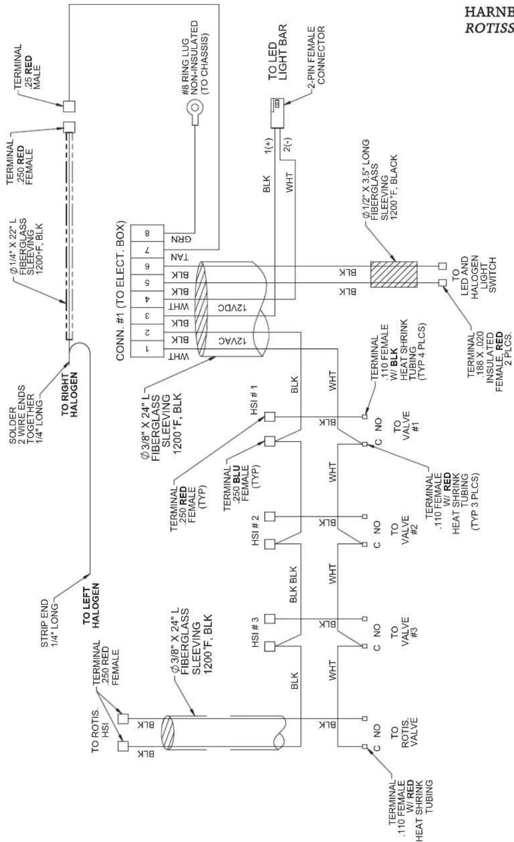
HARNESS 36" WITH ROTISSERIE
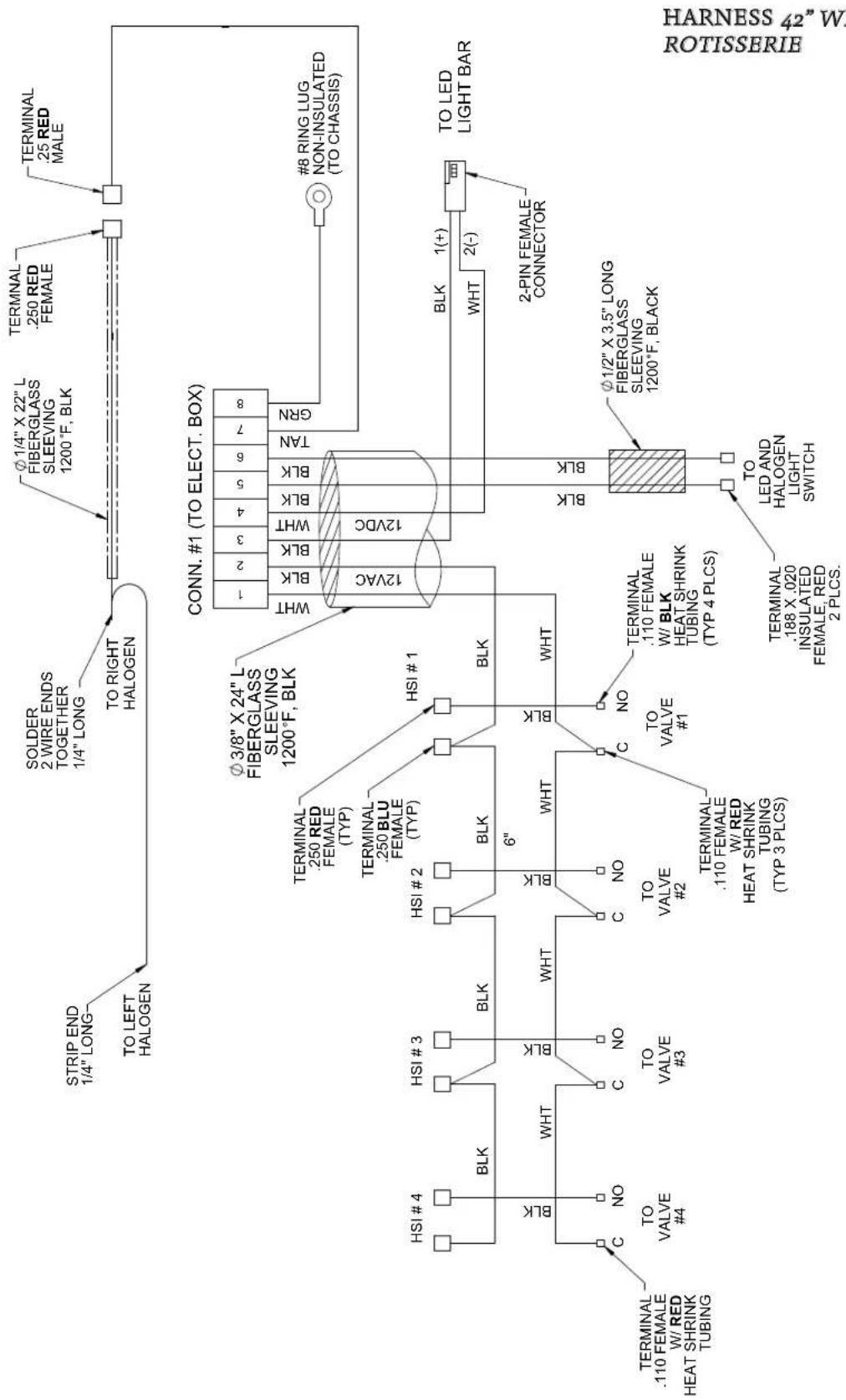
EN
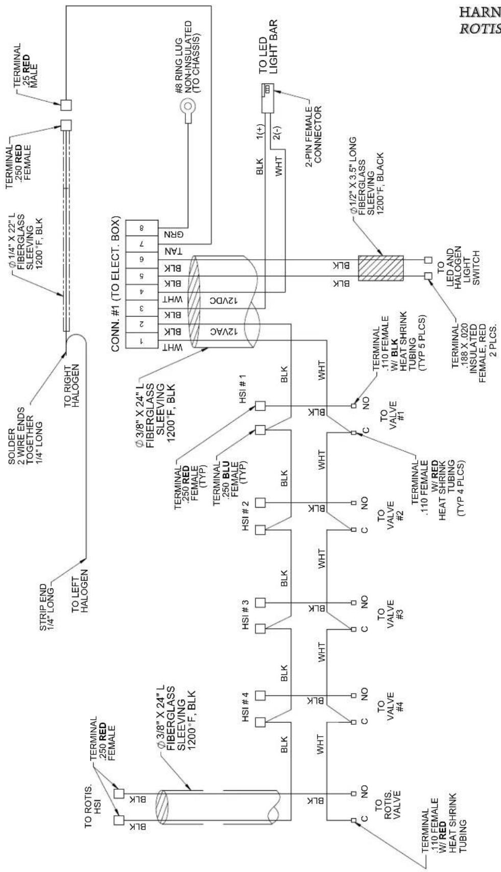
HARNESS 42" WITH ROTISSERIE
PARTS LIST
Please visit the Aspire by Hestan website to access the parts list for your Aspire by Hestan product: www.hestanaspire.com.
SERVICE
All warranty and non-warranty repairs should be performed by qualified service personnel. To locate an authorized service agent in your area, contact your Hestan dealer, local representative, or the manufacturer. Before you call, please have the model number and serial number information ready. This information is shown on the rating sticker affixed to the underside of the drip tray of your appliance.
Hestan Commercial Corporation
3375 E. La Palma Avenue
Anaheim, CA 92806
(888) 905-7463
OUTDOOR GAS PRODUCT LIMITED WARRANTY
WHAT THIS LIMITED WARRANTY COVERS
Hestan Commercial Corporation ("HCC") warrants to the original consumer purchaser of an Aspire by Hestan outdoor gas product (the "Product") from an HCC authorized dealer that the Product is free from defective materials or workmanship for a period of one (1) year from the date of original retail purchase or closing date for new construction, whichever period is longer ("Limited Warranty Period"). HCC agrees to repair or replace, at HCC's sole option, any part or component of the Product that fails due to defective materials or workmanship during the Limited Warranty Period. This Limited Warranty is not transferable and does not extend to anyone beyond the original consumer purchaser ("Purchaser"). This Limited Warranty is valid only on Products purchased and received from an HCC authorized dealer in the fifty United States, the District of Columbia and Canada. This Limited Warranty applies only to Products in non-commercial use and does not extend to Products used in commercial applications.
HOW TO OBTAIN WARRANTY SERVICE
If the Product fails during the Limited Warranty Period for reasons covered by this Limited Warranty, the Purchaser must immediately contact the dealer from whom the Product was purchased or HCC at 888.905.7463.
Purchaser is responsible for making the Product reasonably accessible for service or for paying the cost to make the Product reasonably accessible for service. Service is to be provided during normal business hours of the authorized Hestan Commercial Service Provider. To the extent Purchaser requests service outside of the normal business hours of the authorized Hestan Commercial Service Provider, Purchaser will pay the difference between regular rates and overtime or premium rates. Purchaser is required to pay all travel costs for travel beyond 50 miles (one way) from the nearest authorized Hestan Commercial Service Provider.
EXTENSIONS TO ONE YEAR LIMITED WARRANTY PERIOD:
In addition to the One-Year Limited Warranty, the following components have extended warranty coverage as specifically set forth below:
-
The Product's stainless steel grill body, stainless tubular grill burners, Scar burners and rotisserie infrared burner (where applicable) are warranted to be free from defects in material and workmanship under normal non-commercial use and service for the lifetime of the original Purchaser. This excludes surface corrosion, scratches, and discoloration which may occur during normal use and is limited to replacement of the defective part(s), with the Purchaser paying all other costs, including labor, shipping and handling, as applicable.
-
The Product's cooking grates and warming rack are warranted to be free from defects in material and workmanship under normal non-commercial use and service, for a period of ten (10) years from the original date of purchase. This excludes surface corrosion, scratches, and discoloration which may occur during normal use and is limited to replacement of the defective part(s), with the Purchaser paying all other costs, including labor, shipping and handling, as applicable.
-
The Product's spit rod, briquette trays, manifolds, gas valves and sealed burner assemblies (where applicable) are warranted to be free from defects in material and workmanship, under normal non-commercial use and service, for a period of five (5) years from the original date of purchase. This is limited to replacement of the defective parts, with the Purchaser paying all other costs, including labor, shipping, and handling, as applicable.
OUTDOOR GAS PRODUCT LIMITED WARRANTY(continued)
- All other grill components are warranted to be free from defects in material and workmanship, under normal non-commercial use and service, for a period of two (2) years from the original date of purchase. This is limited to replacement of the defective parts, with the Purchaser paying all other costs, including labor, shipping, and handling, as applicable.
WHAT THIS LIMITED WARRANTY DOES NOT COVER:
This Limited Warranty does not cover and HCC will not be responsible for and will not pay for: damage to or defects in any Product not purchased from an HCC authorized dealer; color variations in color finishes or other cosmetic damage; failure or damage from abuse, misuse, accident, fire, natural disaster, commercial use of the Product, or loss of electrical power or gas supply to the Product; damage from alteration, improper installation, or improper operation of the Product; damage from improper or unauthorized repair or replacement of any part or component of the Product; damage from service by someone other than an authorized agent or representative of the Hestan Commercial Service Network; normal wear and tear; damage from exposure of the Product to a corrosive atmosphere containing chlorine, fluorine, or any other damaging chemicals; damage resulting from the failure to provide normal care and maintenance to the Product; damage HCC was not notified of within the Limited Warranty Period; and incidental and consequential damages caused by any defective material or workmanship.
ARBITRATION:
This Limited Warranty is governed by the Federal Arbitration Act. Any dispute between Purchaser and HCC regarding or related to the Product or to this Limited Warranty shall be resolved by binding arbitration only on an individual basis with Purchaser. Arbitration will be conducted by the American Arbitration Association (“AAA”) in accordance with its Consumer Arbitration Rules or by JAMS. The arbitration hearing shall be before one arbitrator appointed by the AAA or JAMS. The arbitrator shall not conduct class arbitration and Purchaser shall not bring any claims against HCC in a representative capacity on behalf of others.
LIMITATION OF LIABILITY:
This Limited Warranty is the final, complete and exclusive agreement between HCC and Purchaser regarding the Product.
THERE ARE NO EXPRESS WARRANTIES OTHER THAN THOSE LISTED AND DESCRIBED ABOVE. NO WARRANTIES WHETHER EXPRESS OR IMPLIED, INCLUDING, BUT NOT LIMITED TO, ANY IMPLIED WARRANTIES OF MERCHANTABILITY OR FITNESS FOR A PARTICULAR PURPOSE SHALL APPLY AFTER THE LIMITED WARRANTY PERIOD STATED ABOVE. NO OTHER EXPRESS WARRANTY OR GUARANTY GIVEN BY ANY PERSON, FIRM OR CORPORATION WITH RESPECT TO THIS PRODUCT SHALL BE BINDING ON HCC. HCC ASSUMES NO RESPONSIBILITY THAT THE PRODUCT WILL BE FIT FOR ANY PARTICULAR PURPOSE, EXCEPT AS OTHERWISE PROVIDED BY APPLICABLE LAW.
HCC SHALL NOT BE LIABLE FOR LOSS OF REVENUE OR PROFITS, FAILURE TO REALIZE SAVINGS OR OTHER BENEFITS, OR ANY OTHER SPECIAL, INCIDENTAL OR CONSEQUENTIAL DAMAGES CAUSED BY THE USE, MISUSE OR INABILITY TO USE THE PRODUCT, REGARDLESS OF THE LEGAL THEORY ON WHICH THE CLAIM IS BASED, AND EVEN IF HCC HAS BEEN ADVISED OF THE POSSIBILITY OF SUCH DAMAGES. NO RECOVERY OF ANY KIND AGAINST HCC SHALL BE GREATER IN AMOUNT THAN THE PURCHASE PRICE OF THE PRODUCT.
WITHOUT LIMITING THE FOREGOING, YOU ASSUME ALL RISK AND LIABILITY FOR LOSS, DAMAGE OR INJURY TO YOU AND YOUR PROPERTY AND TO OTHERS AND THEIR PROPERTY ARISING OUT OF THE USE, MISUSE OR INABILITY TO USE THE PRODUCT NOT CAUSED DIRECTLY BY THE NEGLIGENCE OF HCC. THIS LIMITED WARRANTY STATES YOUR EXCLUSIVE REMEDY.
No oral or written representation or commitment given by anyone, including but not limited to, an employee, representative or agent of HCC will create a warranty or in any way increase the scope of this express Limited One Year Warranty. If there is any inconsistency between this Limited Warranty and any other agreement or statement included with or relating to the Product, this Limited Warranty shall govern. If any provision of this Limited Warranty is found invalid or unenforceable, it shall be deemed modified to the minimum extent necessary to make it enforceable and the remainder of the Limited Warranty shall remain valid and enforceable according to its terms.
INTERACTION OF LAWS WITH THIS LIMITED WARRANTY:
Some states, provinces or territories may not allow limitations on how long an implied warranty lasts or the exclusion or limitation of incidental or consequential damages, so the above limitations or exclusions may not apply to you. Some states, provinces or territories may provide for additional warranty rights and remedies, and the provisions contained in this Limited Warranty are not intended to limit, modify, take away from, disclaim or exclude any mandatory warranty requirements provided by states, provinces or territories, including certain implied warranties. This warranty gives you specific legal rights, and you may also have other rights which vary depending on location.
Any questions about this Limited Warranty may be directed to Hestan Commercial Corporation at (888) 905-7463.
DANGER
natural_image
Line drawing of a portable electrical enclosure with three buttons and a lid (no text or symbols)natural_image
Line drawing of a portable electric stove with control panel and wheels (no text or symbols)MODÈLES ENCASTRÉS
Hestan Commercial Corporation
3375 E. La Palma Avenue
Anaheim, CA 92806
(888) 905-7463
GARANTIE LIMITÉE
ÉLÉMENTS COUVERTS PAR LA PRÉSENTE GARANTIE LIMITÉE
Hestan Commercial Corporation
3375 E. La Palma Ave
Anaheim, CA 92806
(888) 905-7463
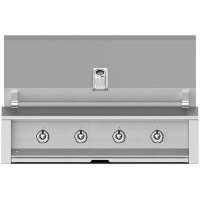

- ASPIRE
- BY HESTAN
- OUTDOOR COOKING
- Message from Aspire by Hestan:
- Welcome to Aspire by Hestan
- DANGER
- ! DANGER
- WARNING
- BUILT-IN MODELS
- FREESTANDING MODELS
- PRECAUTIONS - BEFORE YOU USE YOUR GRILL
- PRECAUTIONS - BEFORE YOU USE YOUR GRILL(continued)
- REGULATORY / CODE REQUIREMENTS
- STATE OF MASSACHUSETTS
- CALIFORNIA PROPOSITION 65 - WARNING
- PORTABLE LP GAS CYLINDERS (continued)
- LOCATING AND ASSEMBLING THE GRILL
- LOCATING AND ASSEMBLING THE GRILL (continued)
- CLEARANCES
- SUPPLEMENTARY VENTILATION
- GAS SUPPLY
- CONVERSION KITS
- HIGH ALTITUDE KITS
- GAS CONNECTION - LIQUID PROPANE (LP) CYLINDER
- GAS CONNECTION - LP PIPED SYSTEMS
- LP TANK RESTRAINT
- LEAK TESTING
- GENERAL
- BEFORE TESTING
- TO TEST
- IMPORTANT NOTE - ALWAYS CHECK FOR LEAKS AFTER EVERY LP CYLINDER CHANGE.
- BURNER ADJUSTMENTS
- U-BURNER FLAME ADJUSTMENT
- GAS CONNECTIONS (continued)
- BURNER REMOVAL BEFORE AIR SHUTTER ADJUSTMENT
- AIR SHUTTER ADJUSTMENT
- Light the burner and adjust as follows:
- VALVE ADJUSTMENTS
- ADJUSTMENT STEPS
- INFRARED BURNER FLAME ADJUSTMENT
- ELECTRICAL SUPPLY
- ELECTRICAL SUPPLY(continued)
- KEEP ANY ELECTRICAL CORD AND FUEL SUPPLY HOSE AWAY FROM ANY HEATED SURFACES.
- ELECTRICAL BOX
- IMPORTANT - READ ALL INSTRUCTIONS BEFORE YOU BEGIN
- LIGHTING INSTRUCTIONS
- CONTROL KNOB LAYOUT
- LIGHTING GRILL BURNERS (U-burner or Sear Burner)
- LIGHTING ROTISSERIE BURNER
- MATCH LIGHTING INSTRUCTIONS
- PREHEATING
- TEMPERATURE GAUGE
- COOKING WITH U-BURNERS AND SEAR BURNERS
- COOKING WITH THE ROTISSERIE
- THE MOTOR
- THE SPIT & FORKS
- THE ROTISSERIE BURNER
- WOOD CHIP SMOKER
- CLEANING AND MAINTENANCE
- STAINLESS STEEL CARE
- RUST-BROWN MARKS
- PITTING
- FOODSTUFFS
- CARE OF PAINTED SURFACES (IF APPLICABLE)
- CARE & MAINTENANCE OF GRILL COMPONENTS
- GRILL GRATE AND WARMING RACK
- DRIP TRAY
- GRILL BURNERS
- ROTISSERIE BURNER CLEANING
- SEAR BURNER CLEANING
- ORIFICE CLEANING
- IGNITERS
- CLEANING THE BRIQUETTES AND TRAYS
- LIGHT BULB REPLACEMENT
- ADDITIONAL CONSIDERATIONS
- PARTS LIST
- SERVICE
- OUTDOOR GAS PRODUCT LIMITED WARRANTY
- WHAT THIS LIMITED WARRANTY COVERS
- HOW TO OBTAIN WARRANTY SERVICE
- EXTENSIONS TO ONE YEAR LIMITED WARRANTY PERIOD:
- OUTDOOR GAS PRODUCT LIMITED WARRANTY(continued)
- WHAT THIS LIMITED WARRANTY DOES NOT COVER:
- ARBITRATION:
- LIMITATION OF LIABILITY:
- INTERACTION OF LAWS WITH THIS LIMITED WARRANTY:
- GARANTIE LIMITÉE
- ÉLÉMENTS COUVERTS PAR LA PRÉSENTE GARANTIE LIMITÉE
Brand : Hestan
Model : EAB30-NG
Category : Grill plate