KVL30 - Basket Hestan - Free user manual and instructions
Find the device manual for free KVL30 Hestan in PDF.


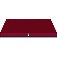
| Product Type | Built-in (integrated) range hood |
| Brand | Hestan |
| Model | KVL30 |
| Width | 30 in (76.2 cm) |
| Airflow | 600 CFM (approx. 1020 m³/h) |
| Fan Type | Dual (WM2L) with wheels color-coded white and black |
| Power Supply | 120 V~, 60 Hz, 20 A (dedicated circuit) |
| Power Consumption (dual fan) | 2.96 A |
| Speed Control | Variable speed rotary |
| Lighting | Dimmable (rotary dimmer) |
| Noise Level | 6.5 sones (at maximum speed) |
| Duct Required | 8 in (20.3 cm) round or equivalent (50 in²) |
| Material | Stainless steel |
| Filters | Removable shield and housing, dishwasher safe |
| Maintenance | Regular cleaning of shields and blower housings |
| Safety | Grounding required; connect to GFCI protected circuit for covered outdoor use |
| Installation | By a qualified electrician/installer |
| Warranty | 3-year limited (parts and labor), additional 5 years on motor |
| Optional Accessories | Transition kits, roof caps, wall vents (AKVWL8, AKVT6810, etc.) |
| Recommended Use | Indoor or covered outdoor |
Frequently Asked Questions - KVL30 Hestan
User questions about KVL30 Hestan
0 question about this device. Answer the ones you know or ask your own.
Ask a new question about this device
Download the instructions for your Basket in PDF format for free! Find your manual KVL30 - Hestan and take your electronic device back in hand. On this page are published all the documents necessary for the use of your device. KVL30 by Hestan.
USER MANUAL KVL30 Hestan
Installation, Use and Care Manual
HESTAN
WARNING
IF THE INFORMATION IN THIS MANUAL IS NOT FOLLOWED EXACTLY, A FIRE OR EXPLOSION MAY RESULT CAUSING PROPERTY DAMAGE, PERSONAL INJURY, OR DEATH.
Do not store or use gasoline or other flammable vapors and liquids in the vicinity of this or any other appliance.
Installation and service must be performed by a qualified installer or service agency.
DO NOT REPAIR, REPLACE OR REMOVE ANY PART OF THE APPLIANCE UNLESS SPECIFICALLY RECOMMENDED IN THE MANUAL. IMPROPER INSTALLATION, SERVICE OR MAINTENANCE CAN CAUSE INJURY OR PROPERTY DAMAGE. REFER TO THIS MANUAL FOR GUIDANCE. ALL OTHER SERVICING SHOULD BE DONE BY A HESTAN AUTHORIZED SERVICE TECHNICIAN.
READ THESE INSTRUCTIONS CAREFULLY AND COMPLETELY BEFORE INSTALLING OR USING YOUR APPLIANCE TO REDUCE THE RISK OF FIRE, BURN HAZARD, OR OTHER INJURY. KEEP THIS MANUAL FOR FUTURE REFERENCE.
SAFETY DEFINITIONS
WARNING
THIS INDICATES THAT DEATH OR SERIOUS INJURY MAY OCCUR AS A RESULT OF NOT OBSERVING THIS WARNING
CAUTION
THIS INDICATES THAT MINOR OR MODERATE INJURY MAY OCCUR AS A RESULT OF NOT OBSERVING THIS WARNING.
NOTICE
THIS INDICATES THAT DAMAGE TO THE APPLIANCE OR PROPERTY MAY OCCUR AS A RESULT OF NOT OBSERVING THIS WARNING.
INSTALLER: LEAVE THIS MANUAL WITH THE OWNER OF THE APPLIANCE.
HOMEOWNER: RETAIN THIS MANUAL FOR FUTURE REFERENCE.
Message from Hestan: Message from Hestan:
Hestan's award-winning culinary innovations and purpose-built features reinvented the restaurant kitchen and redefined culinary experience in some of America's most acclaimed restaurants. Hestan now takes this performance from the back of the house and puts it front and center in yours. Thoughtfully designed and meticulously built, Hestan will serve you beautifully for years to come.
Hestan is the only residential brand born from the dreams and demands of professional chefs. From ranges to refrigeration, every detail is designed to deliver the performance and reliability expected in a restaurant – now available for you.
We appreciate you choosing Hestan, and we promise to deliver the very best to you.
Welcome to Hestan Welcome to Hestan

TABLE OF CONTENTS
1 SAFETY PRECAUTIONS-BEFORE YOU BEGIN
4 MODEL NUMBERS
4 RATING LABEL
5 REGULATORY / CODE REQUIREMENTS
5 USING THE VENTILATION SYSTEM
6 CLEANING AND MAINTENANCE
9 TROUBLESHOOTING
10 DUCTING DO'S AND DON'TS
11 INSTALLATION
16 VENT ACCESSORIES
17 PARTS / SERVICE
17 LIMITED WARRANTY
SAFETY PRECAUTIONS - BEFORE YOU BEGIN
When properly cared for, your Hestan ventilation system will provide safe, reliable service for many years. When using this ventilation system, basic safety practices must be followed as described in the following pages.
IMPORTANT: Save these instructions for the local Utility Inspector's use.
INSTALLER: Please leave these Installation Instructions with the owner.
OWNER: Please read these Instructions and save them for future reference.
WARNING
ELECTRICAL SHOCK HAZARDELECTRICAL SHOCK HAZARD
It is the responsibility of the user to have the appliance connected by a licensed electrician in accordance with all applicable codes and standards, including fire-related construction. See step 11 - "WIRING CONNECTION:" on page 14 for details.

ELECTRICAL SUPPLY AND GROUNDING ELECTRICAL SUPPLY AND GROUNDING
- This appliance must be grounded. See step 11 - "WIRING CONNECTION:" on page 14 for instructions.
- This appliance must be connected to 120 VAC Single Phase, 60Hz , with a dedicated 20 amp circuit.
- OWNER: Have the installer show you where the electric circuit breaker is located so you know how to shut off the power to this appliance.
Suitable for use in covered outdoor applications when installed in a GFCI protected branch circuit.
GENERAL SAFETY PRECAUTIONSGENERAL SAFETY PRECAUTIONS
When properly cared for, your Hestan ventilation liner has been designed to be a safe, reliable ventilation system. Read all instructions carefully before using this ventilation system. When using kitchen appliances, basic safety precautions must be followed.

TO REDUCE THE RISK OF FIRE, ELECTRIC SHOCK, OR INJURY TO PERSONS, OBSERVE THE FOLLOWING:
a) Use this ventilation system only as intended by the manufacturer. If you have any questions, contact the manufacturer.
b) Before servicing or cleaning unit, switch power off at service panel and lock the service disconnecting means to prevent power from being switched on accidentally. When the service disconnecting means cannot be locked, securely fasten a prominent warning device, such as a tag, to the service panel.

FOR GENERAL VENTILATING USE ONLY. DO NOT USE TO EXHAUST HAZARDOUS OR EXPLOSIVE MATERIALS AND VAPORS.

TO REDUCE THE RISK OF A RANGE TOP GREASE FIRE:
a) Never leave burners or surface units unattended at high settings. Boilovers cause smoking and greasy spillovers that may ignite. Heat oils slowly on low or medium settings.
b) Always turn hood ON when cooking at high heat or when flambéing food (i.e. Crepes Suzette, Cherries Jubilee, Peppercorn Beef Flambe).
c) Clean ventilating fans frequently. Grease should not be allowed to accumulate on fan or filter.
d) Use proper pan size. Always use cookware appropriate for the size of the burner or surface element.

TO REDUCE THE RISK OF INJURY TO PERSONS, IN THE EVENT OF A RANGE TOP GREASE FIRE, OBSERVE THE FOLLOWING*:
a) SMOTHER FLAMES with a close-fitting lid, cookie sheet, or metal tray, then turn off the burner. BE CAREFUL TO PREVENT BURNS. If the flames do not go out immediately, EVACUATE AND CALL THE FIRE DEPARTMENT.
b) NEVER PICK UP A FLAMING PAN - You may be burned.
c) DO NOT USE WATER, including wet dish cloths or towels - a violent steam explosion will result.
d) Use an extinguisher ONLY IF:
- You have a Class ABC or Class K fire extinguisher and you already know how to operate it.
- The fire is small and contained in the area where it started.
- The fire department is being called.
-
You can fight the fire with your back to an exit.
-
Based on "Kitchen Fire Safety Tips" published by NFPA
WARNING
BURN HAZARD
This ventilation system is intended for use with ranges or cooktops, which can get very hot during operation. Observe the warnings and cautions for the cooking appliance.
This ventilation system should be serviced only by a Hestan authorized service technician. Contact the nearest authorized service center for examination, repair or adjustment.
Do not repair or replace any part of the system unless specifically recommended. Refer service to an authorized servicer.
Do not operate this ventilation system if it is not working properly or if it has been damaged, until an authorized servicer has examined it.
Install or locate this ventilation system only in accordance with the Installation section of this manual. Do not cover or block any openings on this ventilation system.
It is highly recommended that a suitable kitchen fire extinguisher (Class ABC or K) be readily available and highly visible next to any cooking appliance.
SAFETY DURING CLEANING SAFETY DURING CLEANING
Clean only ventilation system parts listed in this manual, in the manner specified in this manual.
Note: the "ventilating fans" and "filter" in the previous warnings refer to the blower wheel(s), blower housing(s), and blower shield(s). See "CLEANING" on page 7 for parts identification and cleaning instructions.
THIS MANUAL SHOULD REMAIN WITH THE HOMEOWNER FOR FUTURE REFERENCE.
MODEL NUMBERS
| MODEL NO. | DESCRIPTION BLOWER PACKAGE | |
| KVL 30 | 30" Ventilation Liner 600 cfm Kitchen Ventilation System WM2L Dual | |
| KVL 36 | 36" Ventilation Liner 600 cfm Kitchen Ventilation System WM2L Dual | |
| KVL 42 | 42" Ventilation Liner 900 cfm Kitchen Ventilation System WM2L Dual + WM1L Single | |
| KVL 48 | 48" Ventilation Liner 900 cfm Kitchen Ventilation System WM2L Dual + WM1L Single | |
| KVL 54 | 54" Ventilation Liner 1200 cfm Kitchen Ventilation System Two WM2L Duals | |
RATINGRATINGS
| Blower Package | Amps | CFM SP@0.0** | Equivalent CFM** | CFM SP@0.1** | CFM SP@0.2** | CFM SP@0.3** | Minimum Round Duct Size | Sones *** |
| WM2L Dual 2 | 9600 | 531480 | 430 | 8" (50 in. | 2) | 6.5 | ||
| WM2L Dual + WM1L Single | 4.4900 | 1350 | 804725 | 55 | AKVT6810: | 10" (79 in.2) | 6.3 | |
| Two WM2L Duals | 5.8 | 1200 | 1800 | 1062 | 960 | 860 | AKVT8812: 12" (113 in.3) | 6.6 |
All units 115 VAC 60 Hz 1550 RPM
- Static Pressure in inches water column.
** When comparing the Hestan system with blower units made by other manufacturers, use the "Equivalent CFM".
**Ratings in accordance with the Standard Test Code by the Energy Systems Laboratory of the Texas Engineering Experiment Station.
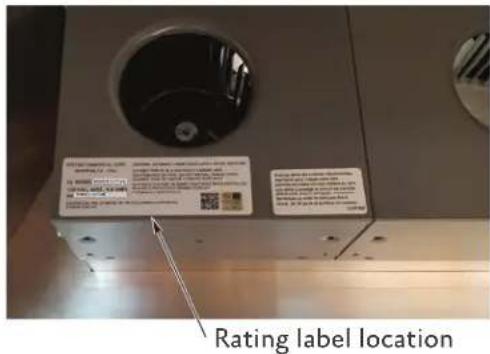
RATING LABEL
The rating label contains important information about your Hestan appliance such as the model and serial number, electrical rating, and minimum installation clearances.
The rating label is located on the blower housing.
If service is necessary, contact Hestan Customer Care with the model and serial number information shown on the label.
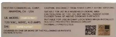
Typical rating label
REGULATORY / CODE REQUIREMENTS
Installation of this ventilation system must be made in accordance with local codes. In the absence of local codes, this unit should be installed in accordance with the National Electrical Code and local codes.
This appliance must be electrically grounded in accordance with local codes or in the absence of local codes with the National Electrical Code ANSI/NFPA 70, or Canadian Electrical code CSA C22.1.
USING THE VENTILATION SYSTEM
FEATURES OF THE VENTILATION SYSTEM FEATURES OF THE VENTILATION SYSTEM
Speed controls are provided for the blower assembly. Two-blower systems will have one speed control knob, while three- or four-blower systems will have two speed control knobs.
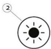
A control knob is provided for lighting intensity.
The controls layout will be similar to that shown below.
USING THE HOOD USING THE HOOD
The user can start with the hood on the lowest setting, and then increase speed and/or turn on additional blowers as required. Using the hood at high settings may increase heating or air conditioning requirements and costs for the house.
BLOWER CONTROL KNOB BLOWER CONTROL KNOB
To operate the blower(s), rotate the knob through the blower speed settings by turning it clockwise (facing the knob).
Rotate the knob counter-clockwise to reduce the blower speed.
LIGHT CONTROL KNOB LIGHT CONTROL KNOB
To operate the lights, rotate the knob through the light intensity settings by turning it clockwise (facing the knob). Rotate the knob counter-clockwise to dim the lights or turn them off.
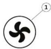
Controls for two blowers

Controls for three and four blowers
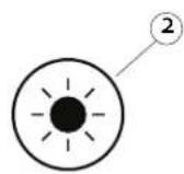
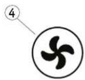
| Item | Function |
| 1 | Blower control |
| 2 | Light control |
| 3 | Blower control blowers 1 & 2 |
| 4 | Blower control, blower 3 or blowers 3 & 4 |
EN
CLEANING AND MAINTENANCE
CLEANING THE VENTILATION SYSTEM CLEANING THE VENTILATION SYSTEM
Cleaning requirements depend completely on usage and environment. The more high-heat and/or greasy cooking, the more often the hood and blower will need cleaning.
The grease tray and blower aren't visible from the outside, so they must be removed for inspection.
After you've inspected the tray a few times over the course of six months or a year, you'll be able to set a cleaning schedule according to your usage pattern.
HOOD LINERHOOD LINER
Wipe down the interior of the hood liner as needed with a soft cloth and warm soapy water (liquid dish detergent is acceptable). Do not use acids, abrasives, strong detergents, solvents, or scouring pads. Stainless steel should be treated with a quality stainless steel cleaner such as Stainless Steel Magic®. Follow all label instructions. Do not polish across the grain or in circles.
BLOWER HOUSING AND SHELD BLOWER HOUSING AND SHIELD
WARNING
To reduce the risk of personal injury, be sure the power is turned off in the hood before removing the shield(s) and blower housing(s).
The blower captures grease by-products in the blower housing(s) and blower shield(s). The blower shields require more frequent cleaning than the blower housing but cooking usage determines how often each item will need to be cleaned.
| Item# | Description |
| 1 | Blower housing with damper(s) |
| 2 | Blower shield |
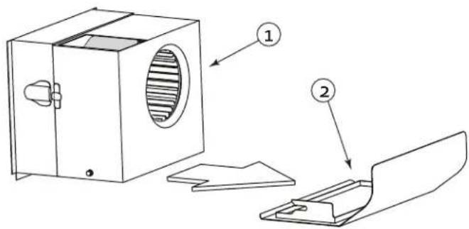
The blower shields are easily removed for cleaning by pulling the blower shield(s) toward the front of the hood.
NOTICE
Be careful to keep the tray level if the hood has been recently used and the grease might still be warm.
Inspect and clean the shield. (Details follow)
To remove the blower housing:
- Unsnap two suitcase latches, one on each side of the housing.
- Support the housing and pull it away from the blower base.
- While pulling it back, gently "tip" it downward to clear the blower wheel(s).
CLEANING CLEANING
Clean the shield(s) and/or blower housing(s) in a sink of warm soapy water (liquid dish detergent) and let soak for a few minutes. Wash with a sponge or dishcloth, rinse and let drain before reinstalling. Alternatively, the blower housing(s) and blower shield(s) may be placed into a dishwasher.
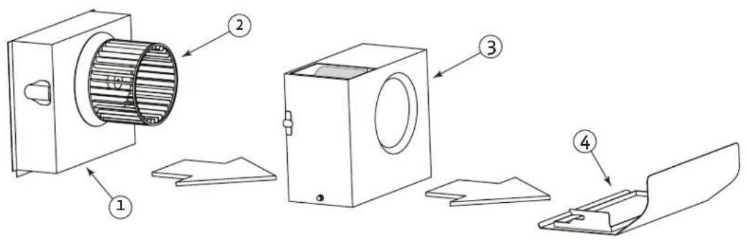
| Item # Description |
| 1 Motor housing |
| 2 Wheel |
| 3 Blower housing with damper(s) |
| 4 Blower shield |
WARNING
To reduce the risk of personal injury, be sure the power is turned off in the hood before removing the shield(s) and blower housing(s).
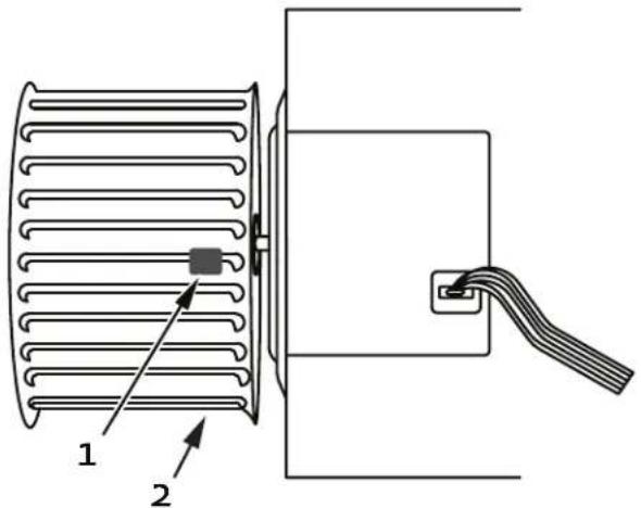
Regular cleaning of the blower housing should prevent grease accumulation on the blower wheel. If grease build-up should occur, the blower wheel may easily be cleaned in place using a soft bristle toothbrush and a common degreaser such as Formula 409®.
WARNING
Take care not to move or lose the metal balancing clips that may be affixed to the wheel.
| Item # | Description |
| 1 | Balancing clip |
| 2 | Blower wheel |
BLOWER WHEEL REMOVAL BLOWER WHEEL REMOVAL
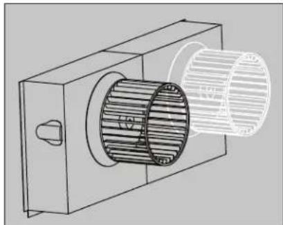
For instances where the blower wheel must be removed, follow the instructions below.
- Removing the blower wheel requires a 1/8'' hex wrench. This may be obtained from your local hardware store or tool supply.
The wheel is retained by a set screw on the side of the hub of the wheel that tightens up against a "flat" spot on the motor shaft. (See illustration on previous page.)
- Locate the set screw on the side of the hub of the wheel
- Insert wrench through the blades of the blower wheel and into the set screw.
- Loosen the set screw 1/2 turn counterclockwise.
If the wheel is difficult to remove, the area where the motor shaft makes contact with the blower wheel hub may need to be sprayed with a common penetrating oil such as WD-40.
After allowing the penetrating oil to soak for a few minutes, push the blower wheel forward slightly, then gently pull the blower wheel off the motor shaft.
- Use caution to avoid bending or distorting the blower wheel and take care not to move or lose the metal balancing clips(1) that may be affixed to the wheel (2).
A soft bristle toothbrush with warm soapy water may be used to clean the blades, or soak the blower wheel in warm soapy water.
BLOWER WHEEL INSTALLATION BLOWER WHEEL INSTALLATION
When reinstalling the wheel onto the motor shaft, make sure the set screw makes direct contact with the "flat spot" on the motor shaft.
- Slide the blower wheel onto the motor shaft as far as it will go, making sure the back of the blower wheel does not touch the motor mount screws protruding from the motor.
- If the motor is too far back, it will rub the motor mount screws, and if it is too far forward, it will rub the inside of the blower housing.
- Adjust the blower wheel slightly to find the correct front-to-rear location.
- Tighten the set screw (clockwise) to lock the blower wheel in the correct position.
NOTICE
For hood liners that have more than one blower wheel, make sure that white blower wheels are matched up with white motor rings, and black blower wheels are matched up with black motor rings.
The hood will not perform properly if blower wheels and motors are mismatched.
MOTOR REPLACEMENT
WARNING
To reduce the risk of personal injury, turn off power to the hood at the breaker or the circuit disconnect before attempting to remove the blower motor.
MOTOR IDENTIFICATION AND POSITIONING MOTOR IDENTIFICATION AND POSITIONING
Motors are color-coded; black and white motors have different rotations and must be installed in the correct positions.
- Housings with a single blower use a white blower and wheel.
- Housings with two blowers use a white blower on the right and black on the left.
Make sure you have the correct motor in each housing position.
-
If the replacement blower motor includes a blower wheel, then you can remove the motor and wheel together. If you will re-use your existing wheel, then you may wish to remove the wheel before removing the motor.
-
Remove the shield and blower housing as described in "BLOWER WHEEL REMOVAL" on page 8.
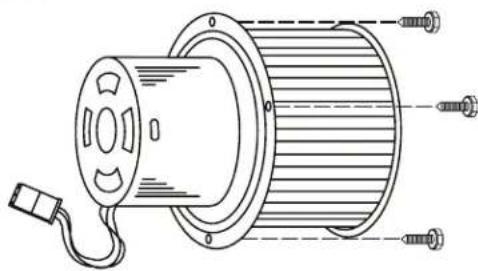
- Use a 1/4'' nut driver to remove the three motor mount screws that attach the motor to the hood.
- Gently pull the motor forward and down.
- Disconnect the wiring harness, remove the old motor.
- To avoid damage to the blower wheel, you may wish to install the motor and then install the wheel onto the motor.
- Lift the new motor so you can connect the wiring harness. Be sure to fully engage the electrical connections and tighten the motor mount screws.
- Check the blower wheel clearance and adjust as needed, as described in "BLOWER WHEEL INSTALLATION" on page 8.
TROUBLESHOOTING
If the hood does not perform satisfactorily, check the following:
- Do the blowers run?
- Are the blower wheels installed on the correct motors? (black wheel on black motor, white wheel on white motor)
- Are the motor and wheel assemblies installed in the correct locations?
- Check the damper doors in blower housing(s) - do they move/open freely?
- Check the dampers/vents to outside - do they open freely, with no obstructions?
- Check for damaged or obstructed ductwork.
GENERAL REQUIREMENTSGENERAL REQUIREMENTS
Observe local codes regarding special duct requirements and placement of duct work against combustibles.
- Using recommended transitions (see VENT ACCESSORIES) will ensure proper efficiency.
- Using recommended roof caps or wall louvers (see VENT ACCESSORIES) will ensure proper efficiency.
- Use foil HVAC tape (not grey cloth duct tape) to seal all joints.
- The hood must be ducted to the outdoors without restrictions.
BLOWER REQUIREMENTS BLOWER REQUIREMENTS
The dual blower unit (WM2L, used in all systems) requires 8^ round duct or equivalent (50 square inches). The single blower unit (WM1L, used in addition to the dual blower unit in 900 CFM systems) requires 6^ round duct or equivalent (28 square inches).
COMBINED DUCT SIZE AFTER A TRANSITIONCOMBINED DUCT SIZE AFTER A TRANSITION
Single and Dual (WM1L & WM2L) combine to 10^ round or equivalent 79 square inches using a multi-blower transition such as AKVT6810 (Optional)
Two Duals (Two WM2Ls) combine to 12^ round or equivalent 113 square inches using a multiblower transition such as AKVT8812 (Optional)
DUCTING REQUIREMENTS (DO'S AND DON'TS)
- NEVER reduce the duct size. When combining ducts together, the square inch area of the outlet duct must be equal or greater than the total square inch area of the ducts being combined.
- Only use smooth, galvanized, metal duct. Do not use flexible or corrugated duct. This type of duct will restrict airflow and reduce performance.
- Make the duct run as short and as straight as possible with as few turns as possible.
- Avoid sharp-angled turns. Instead, use smooth, gradual turns such as adjustable elbows or 45 degree angled turns.
- For duct runs over 20 feet, increase the duct diameter by one inch for every ten feet of duct.
- When planning length, a 90 degree elbow is equivalent to 5 feet of duct.
TERMINATION REQUIREMENTS TERMINATION REQUIREMENTS
Airflow must not be restricted at the end of the duct run.
A wall louver or roof cap is required for each duct run.
Every wall Louver or roof cap must include a gravity damper to prevent back drafts.
Do not use screen wire or spring-loaded doors on wall louvers or roof caps.
Do not terminate venting into an attic or chimney.
YES
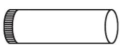
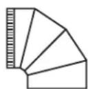
Smooth duct Smooth gradual turn
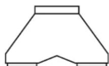
Proper combining of two ducts
NO
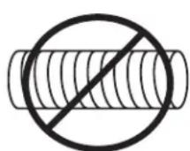

Flexible duct Sharp angled turns
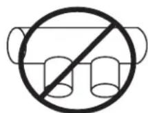
Improper combining of two ducts
WARNING OF FIRE, ELECTRIC SHOCK, OR INJURY TO PERSONS, OBSERVE THE FOLLOWING:
a) Installation work and electrical wiring must be done by qualified person(s) in accordance with all applicable codes and standards, including fire-rated construction.
b) Sufficient air is needed for proper combustion and exhausting of gases through the flue (chimney) of fuel burning equipment to prevent back drafting. Follow the heating equipment manufacturer's guideline and safety standards such as those published by the National Fire Protection Association (NFPA), and the American Society for Heating, Refrigeration, and Air Conditioning Engineers (ASHRAE) and the local code authorities.
c) When cutting or drilling into wall or ceiling, do not damage electrical wiring and other hidden utilities.
d) Ducted fans must always be vented to the outdoors.
WARNING
TO REDUCE THE RISK OF FIRE, USE ONLY METAL DUCTWORK.
TO REDUCE THE RISK OF FIRE OR ELECTRICAL SHOCK, DO NOT USE THIS BLOWER WITH ANY SOLID-STATE SPEED CONTROL DEVICE.
INSTALLATION DETAILS INSTALLATION DETAILS
- Read all instructions thoroughly before beginning installation. Note: These instructions apply to Hestan hood liners only.
See "DUCTING DO'S AND DON'TS" on page 10. - Weight and size: For safe installation, at least two people should be present to lift and hold the liner. For larger liners, it is advisable to have a third person present to assist.
-
Back Venting: If venting out the wall behind the hood instead of venting through the ceiling, see "BACK VENTING" on page 15 for details.
-
When installing a Hestan hood liner, it is recommended that the bottom edge of the liner be located no more than 30^ above the cooking surface for optimum performance.
- Install the duct(s) from the outside of the house down to the location of the exhaust outlet(s) on the top of the liner, allowing room for the optional transitions, if used.
a) If back venting, the elbows should be installed so that the noncrimped end(s) are on the inside of the collar(s) of the exhaust outlet(s). If a transition is used, install the duct so it will engage 1^ of the transition outlet.
b) Consult the connection diagrams (following) for further details on exhaust outlet placement.
c) Use foil HVAC tape (not gray cloth duct tape) to seal all joints. See "VENT ACCESSORIES" on page 16 for available Hestan vent accessories.
CAUTION
Make sure that once the liner is mounted, the motor cooling vents are not obstructed.
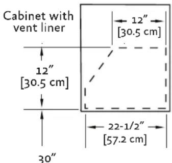
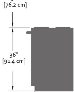
TRANSITION HEIGHTS TRANSITION HEIGHTS:
Dual Blower (WM2L = 600 CFM): no transition - 8'' round duct will connect directly to the top of the liner.
Single and Dual Blower (WM1L + WM2L = 900 CFM): 6'' round duct will connect directly to the top of the liner; 8'' round duct will connect directly to the top of the liner. If using the optional multi-blower transition (AKVT6810, sold separately), a 10'' round duct connects to it 17 - 1/2'' above top of hood.. See "VENT ACCESSORIES" on page 16.
Two Dual Blowers (Two WM2Ls = 1200 CFM):
Two 8^ round ducts connect directly to the top of the liner. If using the optional multi-blower transition (AKVT8812, sold separately), a 12^ round duct connects to it 16 - 1 / 2^ above top of hood. See "VENT ACCESSORIES" on page 16.
CONNECTION DIAGRAMS CONNECTION DIAGRAMS
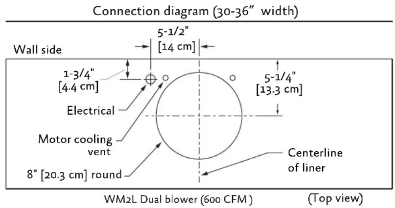
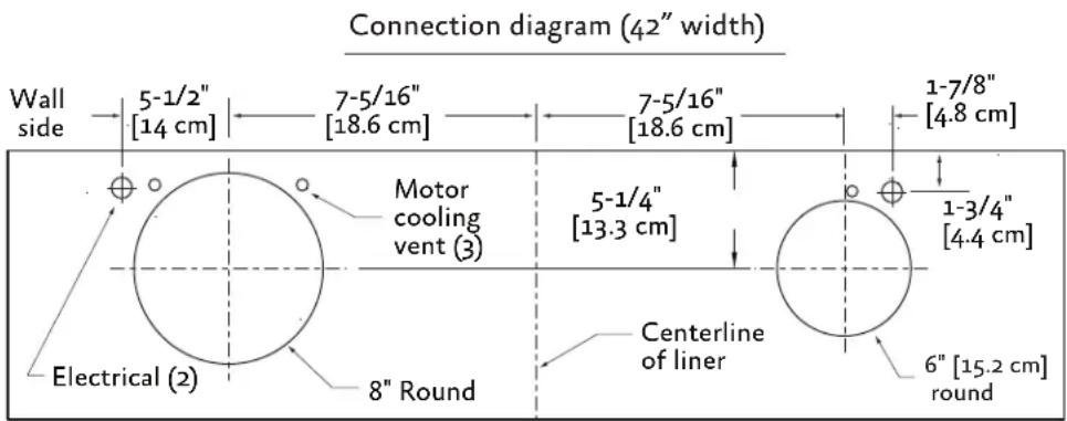
WM2L Dual + WM1L Single blower (900 CFM) (Top view)
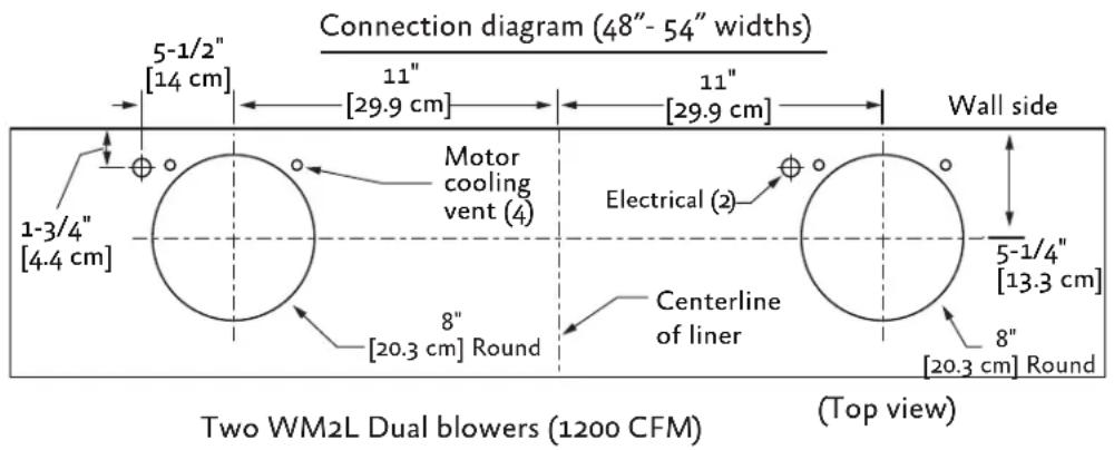
EN
- Remove the liner from its packaging and place the back of the liner on the floor or countertop in front of the wall where it will hang. Save the trim kit and hardware for step 10.
- With the liner on its back facing you, remove the shield(s) and blower housing(s) as follows:
a) Remove the shipping tape that is securing the blower shield(s) inside the liner.
b) Remove the shield(s) by lightly pulling it (lifting it) toward the front of the liner.
c) Gently close the back draft damper(s) from the top side of the liner.
d) To remove the blower housing(s), unsnap the suitcase latches (one on each side of the housing).
e) Support the housing and lift it away from the blower base, then tip it back toward you to clear the blower wheel(s), and then lift it up and out from the liner.
WARNING
Make sure power is off at the supply panel / breaker during service or installation.
- One blower motor must be removed from each blower assembly to access the connection box(es). The blower assembly will have a decal identifying the location of the connection box(es). It is not necessary to remove the blower wheel from the motor.
a) Remove the three screws retaining the blower motor.
b) Pull the motor out far enough so you can reach its electrical connector.
c) Unplug the connector, set the blower motor and screws aside.
-
To lighten the liner for easier handling, the remaining motor(s) can be removed as well, in the same manner as above.
-
WIRING PREPARATION:
a) Install an appropriate 1/2'' UL listed electrical wire clamp through each motor box electrical opening on top of the liner.
b) Install electrical wiring from the service panel to the liner location for each motor box. Consult the connection diagrams (on previous page) for further details on electrical placement. See "ELECTRICAL SUPPLY AND GROUNDING" on page 1 for power requirements.
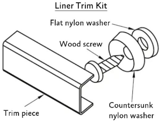
- This step will require the fasteners and hardware in the trim kit.
a) The liner must be lifted into place while guiding the wires into place and aligning the duct(s) or elbow(s) with the exhaust collar(s) or transition.
b) The duct(s) must fit inside the exhaust collar(s).
c) The lower edge of the liner should be flush with the enclosure or slightly above.
-
Install a wood screw with countersunk washer and flat washer into each mounting hole along the bottom edge of the liner.
-
Trim Installation:
a) Install the trim piece for the back side of the liner by hooking one side under the bottom edges of the back countersunk washers.
b) Snap the trim piece over the top of the countersunk washers by applying pressure upward and toward the liner wall.
c) Repeat this process for the front trim piece.
d) After the back and front trim pieces are installed, use the same process for the side trim pieces.
-
A rubber mallet may be used to gently tap the trim pieces into place if needed.
-
WIRING CONNECTION:
a) Bring wires into each of the connection boxes and secure them with the electrical wire clamps.
b) From inside the liner, using UL listed wire nuts, attach the "neutral" wire(s) to the white lead(s), the "hot" wire(s) to the black lead(s), and the ground wire(s) to the green lead(s) inside the motor box(es).

DO NOT OPERATE HOOD WITHOUT A PROPER GROUND CONNECTION.
- For each removed blower motor: Re-plug its connector to the hood wiring, then reinstall the blower motor using the three retaining screws that were previously removed.
- Make sure motors are installed in the correct locations. See "MOTOR IDENTIFICATION AND POSITIONING" on page 9.
- Make sure that the damper(s) open and close smoothly. Replace the blower housing(s) and the blower shield(s).
- Turn Power On, Verify Operation: See "USING THE VENTILATION SYSTEM" on page 5 for proper hood operation. Test all blower and light functions to ensure they are operating properly.
BACK VENTING BACK VENTING
When venting out through the wall, one or two elbows are required, depending on the blower configuration:
ELBOW FOR 6oo CFMELBOW FOR 6oo CFM
Units (hoods/liners) with 600 CFM blower systems require one 8^ elbow for the blower unit
ELBOWS FOR 900 CFM ELBOWS FOR 900 CFM
Units with 900 CFM blower systems require one 8'' elbow and one 6'' elbow
ELBOWS FOR 1200 CFMELBOWS FOR 1200 CFM
Units with 1200 CFM blower systems require two 8'' elbows, one for each 600 CFM blower unit.
Elbow and Transition Heights
Height when fully adjusted to 90 degrees:
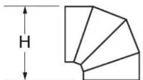
Standard 6^ [15.2 cm] round - 8-1/2" [21.6 cm] Standard 8^ [20.3 cm] round - 10-3/4" [27.3 cm]
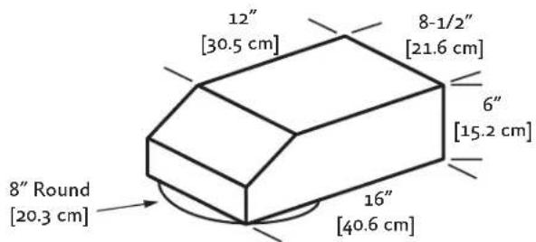
Low profile elbow: 8^ to 6^ × 8 - 1 / 2^ Hestan P/N AKVBE8
600 CFM fan module uses 8^ round 300 CFM fan module uses 6^ round
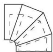
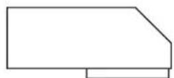
(Drawing Not To Scale)
8" Round
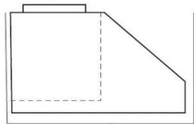
Side View
Hood Enclosure (supplied by customer)
EN

WALL LOVER
MODEL DESCRIPTION
A AKVWL6 6" Round
B AKVWL8 8" Round
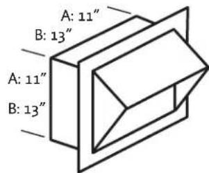
WALL LOUVER
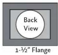
MODELITEM DESCRIPTION
A AKVWL10 10" Round
B AKVWL12 12" Round
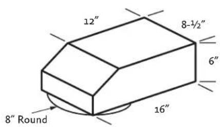
MODEL DESCRIPTION
AKVBE8 8^ Round to 6''× 8 - 1 / 2'' Rect.
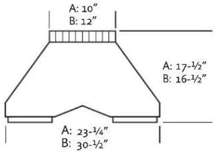
MULTI-BLOWER TRANSITIONLOW PROFILE ELBOV
ITEM MODEL DESCRIPTION
A AKVT6810 6" & 8" to 10"
B AKVT8812 8" & 8" to 12"
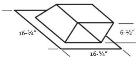
LOW PROFILE ROOF CAP (MINIMUM 4/12 PITCH)
MODEL DESCRIPTION
AKVRC6HP 6" Round
AKVRC8HP 8" Round
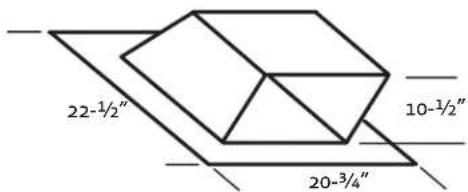
LOW PROFILE ROOF CAP (MINIMUM 4/12 PITCH)
MODEL DESCRIPTION
AKVRC1oHP 10" Round
AKVRC12HP 12" Round
THE INFORMATION IN THIS DOCUMENT IS SUBJECT TO CHANGE AT ANY TIME WITHOUT NOTICE.
SERVICE DATA RECORD SERVICE DATA RECORD
The rating label contains the model number and serial number of the appliance. See page 4 for location of the rating label.
Now is a good time to write this information in the space provided below. Keep your invoice for warranty validation.
Model Number
Serial Number
Date of Installation or Occupancy
PARTS LIST
Please visit the Hestan website to access the parts list for your Hestan Indoor product: www.hestanhome.com.www.hestanhome.com.
SERVICE
All warranty and non-warranty repairs should be performed by qualified service personnel. To locate an authorized service agent in your area, contact your Hestan dealer, local representative, or the manufacturer. Before you call, please have the model number and serial number information ready.
Hestan Commercial Corporation
3375 E. La Palma Avenue
Anaheim, CA 92806
(888) 905-7463
LIMITED WARRANTY
WHAT THIS LIMITED WARRANTY COVERSWHAT THIS LIMITED WARRANTY COVERS
Hestan Commercial Corporation ("HCC") warrants to the original consumer purchaser of a Hestan Indoor Cooking product (the "Product") from an HCC authorized dealer that the Product is free from defective materials or workmanship for a period of three (3) years from the date of original retail purchase or closing date for new construction, whichever period is longer ("Limited Warranty Period"). HCC agrees to repair or replace, at HCC's sole option, any part or component of the Product that fails due to defective materials or workmanship during the Limited Warranty Period. This Limited Warranty is not transferable and does not extend to anyone beyond the original consumer purchaser ("Purchaser"). This Limited Warranty is valid only on Products purchased and received from an HCC authorized dealer in the fifty United States, the District of Columbia and Canada. This Limited Warranty applies only to Products in non-commercial use and does not extend to Products used in commercial applications.
HOW TO OBTAIN WARRANTY SERVICEHOW TO OBTAIN WARRANTY SERVICE
If the Product fails during the Limited Warranty Period for reasons covered by this Limited Warranty, the Purchaser must immediately contact the dealer from whom the Product was purchased or HCC at 888.905.7463.
Purchaser is responsible for making the Product reasonably accessible for service or for paying the cost to make the Product reasonably accessible for service. Service is to be provided during normal business hours of the authorized Hestan Commercial Service Provider. To the extent Purchaser requests service outside of the normal business hours of the authorized Hestan Commercial Service Provider, Purchaser will pay the difference between regular rates and overtime or premium rates. Purchaser is required to pay all travel costs for travel beyond 50 miles (one way) from the nearest authorized Hestan Commercial Service Provider.
EXTENSIONS TO THREE YEAR LIMITED WARRANTY PERIOD:
In addition to the Three-Year Limited Warranty, the following components have extended warranty coverage as specifically set forth below:
- The Product's gas burners (excludes appearance), electric heating elements, blower motors (ventilation hoods), electronic control boards, magnetron tubes and induction generators (where applicable) are warranted to be free from defects in material and workmanship under normal non-commercial use and service for a period of five (5) years of the original Purchaser. This excludes surface corrosion, scratches, and discoloration which may occur during normal use and is limited to replacement of the defective part(s), with the Purchaser paying all other costs, including labor, shipping and handling, as applicable.
WHAT THIS LIMITED WARRANTY DOES NOT COVER WHAT THIS LIMITED WARRANTY DOES NOT COVER:
This Limited Warranty does not cover and HCC will not be responsible for and will not pay for: damage to or defects in any Product not purchased from an HCC authorized dealer; color variations in color finishes or other cosmetic damage; failure or damage from abuse, misuse, accident, fire, natural disaster, commercial use of the Product, or loss of electrical power or gas supply to the Product; damage from alteration, improper installation, or improper operation of the Product; damage from improper or unauthorized repair or replacement of any part or component of the Product; damage from service by someone other than an authorized agent or representative of the Hestan Commercial Service Network; normal wear and tear; damage from exposure of the Product to a corrosive atmosphere containing chlorine, fluorine, or any other damaging chemicals; damage resulting from the failure to provide normal care and maintenance to the Product; damage HCC was not notified of within the Limited Warranty Period; and incidental and consequential damages caused by any defective material or workmanship.
ARBITRATION:ARBITRATION:
This Limited Warranty is governed by the Federal Arbitration Act. Any dispute between Purchaser and HCC regarding or related to the Product or to this Limited Warranty shall be resolved by binding arbitration only on an individual basis with Purchaser. Arbitration will be conducted by the American Arbitration Association ("AAA") in accordance with its Consumer Arbitration Rules or by JAMS. The arbitration hearing shall be before one arbitrator appointed by the AAA or JAMS. The arbitrator shall not conduct class arbitration and Purchaser shall not bring any claims against HCC in a representative capacity on behalf of others.
LIMITATION OF LIABILITY: LIMITATION OF LIABILITY:
This Limited Warranty is the final, complete and exclusive agreement between HCC and Purchaser regarding the Product.
THERE ARE NO EXPRESS WARRANTY OTHER THAN THOSE LISTED AND DESCRIBED ABOVE. NO WARRANTY WHEHER EXPRESS OR IMPLIED, INCLUDING, BUT NOT LIMITED TO, ANY IMPLIED WARRANTY OF MERCHANTABILITY OR FITNESS FOR A PARTICULAR PURPOSE SHALL APPLY AFTER THE LIMITED WARRANTY PERIOD STATED ABOVE. NO OTHER EXPRESS WARRANTY OR GUARANTY GIVEN BY ANY PERSON, FIRM OR CORPORATION WITH RESPECT TO THIS PRODUCT SHALL BE BINDING ON HCC. HCC ASSUMES NO RESPONSIBILITY THAT THE PRODUCT WILL BE FIT FOR ANY PARTICULAR PURPOSE, EXCEPT AS OTHERWISE PROVIDED BY APPLICABLE LAW.
HCC SHALL NOT BE LIABLE FOR LOSS OF REVENUE OR PROFITS, FAILURE TO REALIZE SAVINGS OR OTHER BENEFITS, OR ANY OTHER SPECIAL, INCIDENTAL OR CONSEQUENTIAL DAMAGES CAUSED BY THE USE, MISUSE OR INABILITY TO USE THE PRODUCT, REGARDLESS OF THE LEGAL THEORY ON WHICH THE CLAIM IS BASED, AND EVEN IF HCC HAS BEEN ADVISED OF THE POSSIBILITY OF SUCH DAMAGES. NO RECOVERY OF ANY KIND AGAINST HCC SHALL BE GREATER IN AMOUNT THAN THE PURCHASE PRICE OF THE PRODUCT.
WITHOUT LIMITING THE FOREGOING, YOU ASSUME ALL RISK AND LIABILITY FOR LOSS, DAMAGE OR INJURY TO YOU AND YOUR PROPERTY AND TO OTHERS AND THEIR PROPERTY ARISING OUT OF THE USE, MISUSE OR INABILITY TO USE THE PRODUCT NOT CAUSED DIRECTLY BY THE NEGLIGENCE OF HCC. THIS LIMITED WARRANTY STATES YOUR EXCLUSIVE REMEDY.
No oral or written representation or commitment given by anyone, including but not limited to, an employee, representative or agent of HCC will create a warranty or in any way increase the scope of this express Limited Three Year Warranty. If there is any inconsistency between this Limited Warranty and any other agreement or statement included with or relating to the Product, this Limited Warranty shall govern. If any provision of this Limited Warranty is found invalid or unenforceable, it shall be deemed modified to the minimum extent necessary to make it enforceable and the remainder of the Limited Warranty shall remain valid and enforceable according to its terms.
INTERACTION OF LAWS WITH THIS LIMITED WARRANTY:
Some states, provinces or territories may not allow limitations on how long an implied warranty lasts or the exclusion or limitation of incidental or consequential damages, so the above limitations or exclusions may not apply to you. Some states, provinces or territories may provide for additional warranty rights and remedies, and the provisions contained in this Limited Warranty are not intended to limit, modify, take away from, disclaim or exclude any mandatory warranty requirements provided by states, provinces or territories, including certain implied warranties. This warranty gives you specific legal rights, and you may also have other rights which vary depending on location.
Any questions about this Limited Warranty may be directed to Hestan Commercial Corporation at (888) 905-7463
A VERTISSEMENT
LE NON-RESPECT À LA LETTRE DE CES INSTRUCTIONS PEUT CAUSER UN INCENDIE OU UNE EXPLOSION, QUI POURRAIT ENTRAINER DES DOMMAGES MATÉRIELS, DES BLESSURES OU LA MORT.
CE MANUEL DOIT RESTER AVEC LA PROPRIÉTAIRE POUR RÉFERENCE FUTURE.
NUMÉROS DE MODELE
CONDITIONS DETERMINATION CONDITIONS DE TERMINATION
Hestan Commercial Corporation
3375 E. La Palma Ave.
Anaheim, CA 92806
(888) 905-7463
- WARNING
- SAFETY DEFINITIONS
- Message from Hestan: Message from Hestan:
- TABLE OF CONTENTS
- SAFETY PRECAUTIONS - BEFORE YOU BEGIN
- ELECTRICAL SHOCK HAZARDELECTRICAL SHOCK HAZARD
- ELECTRICAL SUPPLY AND GROUNDING ELECTRICAL SUPPLY AND GROUNDING
- GENERAL SAFETY PRECAUTIONSGENERAL SAFETY PRECAUTIONS
- BURN HAZARD
- SAFETY DURING CLEANING SAFETY DURING CLEANING
- MODEL NUMBERS
- RATINGRATINGS
- RATING LABEL
- REGULATORY / CODE REQUIREMENTS
- USING THE VENTILATION SYSTEM
- FEATURES OF THE VENTILATION SYSTEM FEATURES OF THE VENTILATION SYSTEM
- USING THE HOOD USING THE HOOD
- BLOWER CONTROL KNOB BLOWER CONTROL KNOB
- LIGHT CONTROL KNOB LIGHT CONTROL KNOB
- CLEANING AND MAINTENANCE
- CLEANING THE VENTILATION SYSTEM CLEANING THE VENTILATION SYSTEM
- HOOD LINERHOOD LINER
- BLOWER HOUSING AND SHELD BLOWER HOUSING AND SHIELD
- NOTICE
- CLEANING CLEANING
- BLOWER WHEEL REMOVAL BLOWER WHEEL REMOVAL
- BLOWER WHEEL INSTALLATION BLOWER WHEEL INSTALLATION
- MOTOR REPLACEMENT
- MOTOR IDENTIFICATION AND POSITIONING MOTOR IDENTIFICATION AND POSITIONING
- TROUBLESHOOTING
- GENERAL REQUIREMENTSGENERAL REQUIREMENTS
- BLOWER REQUIREMENTS BLOWER REQUIREMENTS
- COMBINED DUCT SIZE AFTER A TRANSITIONCOMBINED DUCT SIZE AFTER A TRANSITION
- DUCTING REQUIREMENTS (DO'S AND DON'TS)
- TERMINATION REQUIREMENTS TERMINATION REQUIREMENTS
- YES
- NO
- WARNING OF FIRE, ELECTRIC SHOCK, OR INJURY TO PERSONS, OBSERVE THE FOLLOWING:
- INSTALLATION DETAILS INSTALLATION DETAILS
- CAUTION
- CONNECTION DIAGRAMS CONNECTION DIAGRAMS
- DO NOT OPERATE HOOD WITHOUT A PROPER GROUND CONNECTION.
- BACK VENTING BACK VENTING
- Elbow and Transition Heights
- SERVICE DATA RECORD SERVICE DATA RECORD
- PARTS LIST
- SERVICE
- LIMITED WARRANTY
- WHAT THIS LIMITED WARRANTY COVERSWHAT THIS LIMITED WARRANTY COVERS
- HOW TO OBTAIN WARRANTY SERVICEHOW TO OBTAIN WARRANTY SERVICE
- EXTENSIONS TO THREE YEAR LIMITED WARRANTY PERIOD:
- WHAT THIS LIMITED WARRANTY DOES NOT COVER WHAT THIS LIMITED WARRANTY DOES NOT COVER:
- ARBITRATION:ARBITRATION:
- LIMITATION OF LIABILITY: LIMITATION OF LIABILITY:
- INTERACTION OF LAWS WITH THIS LIMITED WARRANTY:
- A VERTISSEMENT
- NUMÉROS DE MODELE
- CONDITIONS DETERMINATION CONDITIONS DE TERMINATION
Brand : Hestan
Model : KVL30
Category : Basket