GOL 26 Professional - Laser level BOSCH - Free user manual and instructions
Find the device manual for free GOL 26 Professional BOSCH in PDF.

| Product type | Automatic optical laser level |
| Brand | Bosch |
| Model | GOL 26 Professional |
| Magnification | 26x |
| Leveling accuracy | 1.6 mm at 30 m |
| Maximum working distance | 100 m |
| Lens aperture | 36 mm |
| Compensator accuracy | ±0.8" |
| Compensator working range | ±15' |
| Magnetic damping | Yes |
| Circular level accuracy | 8 min / 2 mm |
| Horizontal circle measurement system | 1° or 1 Gon |
| Minimum sight | 0.3 m |
| Field of vision | 1.5° |
| Stadia factor | 100 |
| Addition constant | 0 |
| Length | 210 mm |
| Weight | 1.7 kg |
| Mounting thread | 5/8-11 |
| Protection degree | IP54 |
| Housing material | Robust plastic |
| Color | Green/Black |
| Warranty | 1 year (extendable to 2 years upon registration) |
Frequently Asked Questions - GOL 26 Professional BOSCH
User questions about GOL 26 Professional BOSCH
0 question about this device. Answer the ones you know or ask your own.
Ask a new question about this device
Download the instructions for your Laser level in PDF format for free! Find your manual GOL 26 Professional - BOSCH and take your electronic device back in hand. On this page are published all the documents necessary for the use of your device. GOL 26 Professional by BOSCH.
USER MANUAL GOL 26 Professional BOSCH
IMPORTANT: IMPORTANT : IMPORTANTE: Read Before Using Lire avant usage Leer antes de usar

natural_image
Icon of a person reading a book inside a circle (no text or symbols)Operating/Safety Instructions Consignes de fonctionnement/sécurité Instrucciones de funcionamiento y seguridad
GOL 24 GOL 26 GOL 32

natural_image
Line drawing of a Bosch BOSCH surveying instrument with dual scales and no visible text or symbols on the device itself.
BOSCH
Call Toll Free for Consumer Information & Service Locations
flowchart
graph TD
    A["A"] --> B["B"]
    B --> C["C"]
    B --> D["Circle with arrow"]
    D --> E["Circle with arrow"]
    E --> F["Circle with arrow"]
    F --> G["Circle with arrow"]
    style A fill:#fff,stroke:#000
    style B fill:#fff,stroke:#000
    style C fill:#fff,stroke:#000
    style D fill:#fff,stroke:#000
    style E fill:#fff,stroke:#000
    style F fill:#fff,stroke:#000
    style G fill:#fff,stroke:#000

natural_image
Diagram showing two identical mechanical components with circular ends and central slots, labeled Fig. 6 (no text or symbols on the components themselves)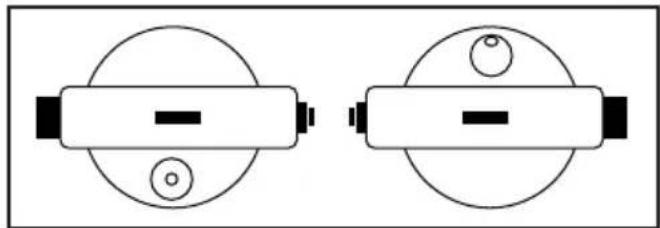
natural_image
Two identical diagrams of cylindrical objects with internal components, no text or symbols present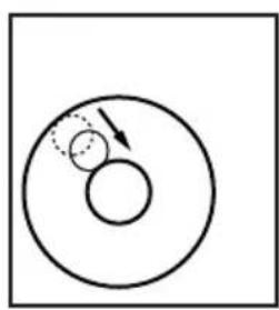
natural_image
Simple diagram showing two concentric circles with an arrow indicating direction, no text or symbols present.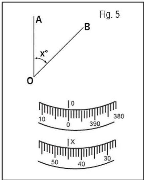
natural_image
Mechanical assembly diagram showing a hand turning a gear-like component with a tool, labeled Fig. 12 (no text or symbols on the diagram itself)General Safety Rules
Work area safety

Keep work area clean and well lit. Cluttered or dark
areas invite accidents.
Personal safety
Stay alert, watch what you are doing and use common sense when operating a tool. Do not use a tool while you are tired or under the influence of drugs, alcohol or medication. A moment of inattention while operating a tool may result in serious
personal injury or incorrect measurement results.
Use and care
Use the correct tool for your application. The correct tool will do the job better and safer.
Store idle tool out of the reach of children and do not allow persons unfamiliar with the tool or these instructions to operate the tool. Tools are dangerous in the hands of untrained users.
Maintain tools. Check for misalignment or binding of moving parts, breakage of parts and any other condition that may affect the operation. If damaged, repair tool before use. Many accidents are caused by poorly maintained tools.
Use the tool, accessories, etc., in accordance with these instructions and in the manner intended for the particular type of tool, taking into account the working conditions and the work to be performed. Use of the tool for operations different from those intended could result in a hazardous situation.
Service
Have your tool serviced by a qualified repair person using only identical replacement parts. This will ensure that the safety and accuracy of the tool is maintained.
Develop a periodic maintenance schedule for tool. When cleaning a tool be careful not to disassemble any portion of the tool since internal components may be misplaced or pinched or may be improperly mounted. Certain cleaning agents such as gasoline, carbon tetrachloride, ammonia, etc. may damage plastic parts.
SAVE THESE INSTRUCTIONS.
Intended Use
This tool is intended to quickly determine and check level points for any construction job.
Preparation
This manual includes specifications for the GOL Series auto level.
WARNING
Verify the calibration of the instrument. Before initial use, follow the test shown in the section "Line-of-sight."
After doing any job using any instrument, it is advised that you check your work. To check your work, set up the instrument in a different
location from the place where you originally set up (approx. 16 m) and reshoot a few of your original targets. The new readings should agree with the first readings.
If the new readings do not agree, you should have the instrument checked by a Bosch Authorized Repair Center, or try the Line-of-sight adjustment.
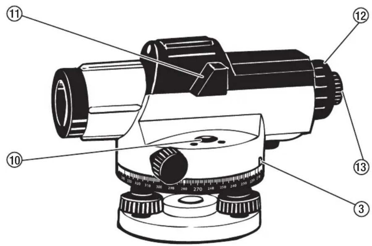
Features
The numbering of the product features shown refers to the illustration of the tool on the graphic page 2.
1 Base Plate
2 Horizontal Circle
3 Horizontal Circle Reference Mark
4 Compensator Lock
5 Focusing Knobs
6 Optical Peep Sight
7 Sunshade / Objective Lens
8 Horizontal Drive Screw
9 Leveling Screw
10 Circular Bubble Vial
11 Vial Sighting Prism
12 Eyepiece Cover
13 Eyepiece Focusing Knob
Technical Data
Automatic Optical Level GOL 32 GOL 26 GOL 24
Material Number 0601068510 0601068010 0601068610
| Magnification | 32X 26X 24X | ||
| Leveling Accuracy | 1/16-in at 100-ft(1.0 mm at 30 m) | 1/16-in at 100-ft (1.6 mm at 30 m) | 1/16-in at 100-ft(1.6 mm at 30 m) |
| Working Range | Up to 400-ft (120 m) | Up to 330-ft (100 m) | Up to 300-ft (91 m) |
| Clear Obj. Aperture | 36 mm | 36 mm | 36 mm |
| Setting Accuracy | ±0.3” | ±0.8” | ±0.8” |
| Telescope | |||
| Image | Erect | Erect | Erect |
| Length | 8.3-in (210 mm) | 8.3-in (210 mm) | 8.3-in (210 mm) |
| Shortest Focusing Length | 1-ft (0.3 m) | 1-ft (0.3 m) | 1-ft (0.3 m) |
| Field of View | 1°30' | 1.5° 1.5° | |
| Stadia Ratio | 100 | 100 | 100 |
| Stadia Addition | 0 | 0 | 0 |
| Compensator | |||
| Leveling Range | ±15' | ±15' | ±15' |
| Magnet Dampening | Yes Yes Yes | ||
| Sensitivity of Bubble | 8 min / 2 mm | 8 min / 2 mm | 8 min / 2 mm |
| Circle Graduation | 1° or 1 Gon | 1° or 1 Gon | 1° or 1 Gon |
| Degree of protection | IP54 | IP54 | IP54 |
| Instrument Net Weight | 3.7 lbs. (1.7 kg) | 3.7 lbs. (1.7 kg) | 3.7 lbs. (1.7 kg) |
| Mounting Thread | 5/8-11 | 5/8-11 | 5/8-11 |
Operation
Initial Operation

WARNING
Verify the calibration of the instrument. Before
initial use, follow the test shown in the section "Line-of-sight."
Protect the tool against moisture and direct sun irradiation.
Do not subject the tool to extreme temperatures or variations in
temperature. For an example, do not leave it in a vehicle for long periods. In case of large variations in temperature, allow the tool to adjust to the ambient temperature before putting it into operation. In case of extreme temperatures or variations in temperature, the accuracy of the tool can be impaired.
Avoid heavy impact or dropping of the tool. After heavy exterior impact on the tool, an accuracy check should always be carried out before continuing to work (see "Leveling Accuracy").
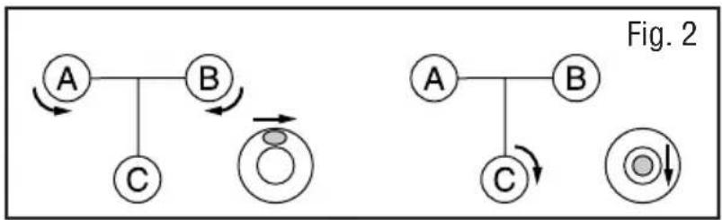
Setting up the instrument and centering the bubble
- Set up the tripod and attach the level using the tripod mounting screw.
- Adjust the tripod legs until the tripod head is roughly level. Center the bubble within the vial by turning the leveling screws as shown in Fig. 2.
2a – Turn screws A and B to move the bubble to the right side.
2b - Turn screw C to center the bubble.
WARNING
Wear eye protection. If Spirit Level leaks, soak up with appropriate absorbent material and dispose of safely. Spirit Level contains flammable liquid that may cause respiratory tract, eye and skin irritation.
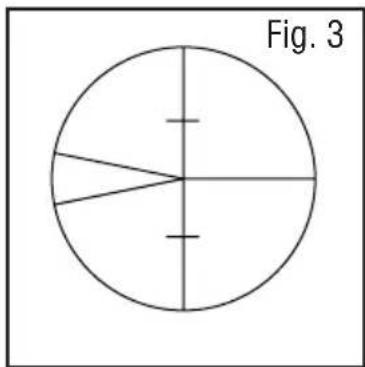
Focusing the instrument
- Focus the cross hairs (Fig. 3) by pointing the telescope towards a bright background or holding a white sheet of paper in front of the objective lens, then turning the eyepiece until the cross hairs are sharp and black.
- Focus the telescope by locating a target, such as a leveling rod, using the optical peep sight. Looking through the eyepiece, use the focusing knob to bring the target into sharp focus. Center the vertical hair within the target using the horizontal drive knobs on either side of the instrument.
WARNING
Do not look through optics directly into the sun.
Eyesight damage may result.
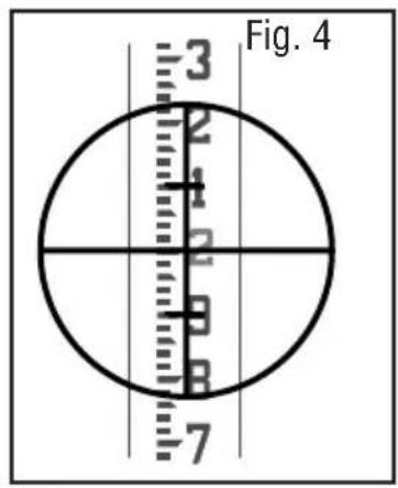
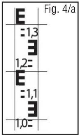
Reading measurements using a leveling rod
Height reading
Read the rod where it is intersected by the horizontal hair. For example, the height reading in Fig. 4 is 2.0ft and Fig. 4/a1,195m.
Distance measurement
Read the rod where it is intersected by the upper and lower stadia hairs; in Fig. 4 (Fig. 4/a) these readings are at 1.9 ft and 2.1 ft (1,352 m and 1,038 m). The stadia ratio is 1:100; therefore, the distance from the instrument to the rod is: (2.1 - 1.9) x 100 = 20 feet - Fig. 4/a (1,352 - 1,038) x 100 = 31,41m.
Angle measurement
As shown in Fig. 5, sight point A and rotate the horizontal circle until the reference mark is on "0". Rotate the level and sight point B; the reference mark will indicate the angle between A and B.
Calibration
WARNING
Verify the calibration of the instrument. Before initial use, follow the test shown in the section "Line-of-sight." Bosch recommends that your instrument be verified for calibrated on a regular interval as well as after rough handling, impact on, or drop of the instrument.
Compensator lock button
Check the compensator for proper operation before use or anytime the operation of the instrument is in question. Push and release the compensator lock button to shake the compensator. The compensator should return to the exact horizontal position sighted before the lock button was pressed.
Circular bubble vial
Center the vial bubble using the leveling screws, then rotate the instrument 180°. The bubble should remain centered (Fig. 6). If the bubble moves out of center, the vial needs adjustment (Fig.7).
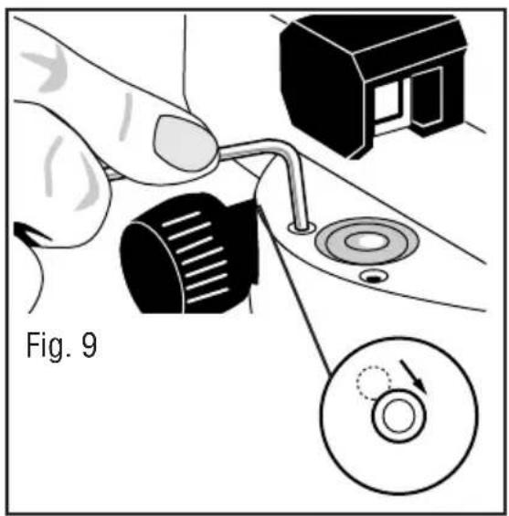
Turn the leveling screws to bring the bubble halfway to center (Fig. 8). Using the Allen wrench, turn the two vial adjustment screws to center the bubble (Fig. 9).
Repeat the above procedure until the bubble remains centered when the level is rotated 180^ .
Line-Of-Sight
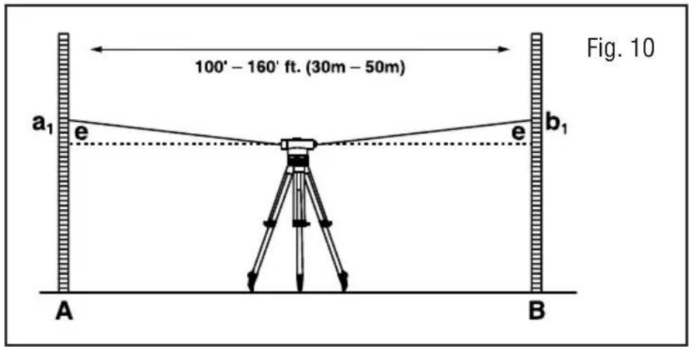
The line-of-sight needs to be horizontal within 3 mm of level to be accurate.
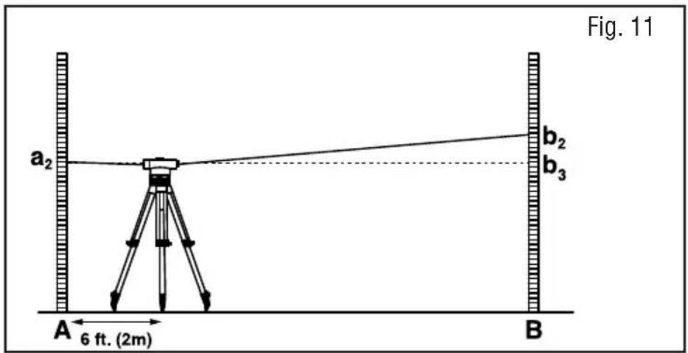
Set up and level the instrument on a tripod midway between two leveling rods set approximately 30 m to 50 m apart. Sight rods A and B; the height readings are a1 and b1 (Fig. 10). The value “H” is equal to (a1 – b1). Move the instrument to within 6 feet (2m) of rod A and re-level. Again sight rods A and B; these height readings are a2 and b2 (Fig. 11).
If a1 - b1 = a2 - b2 = H, the line-of-sight is horizontal. If not, the level should be adjusted as follows.
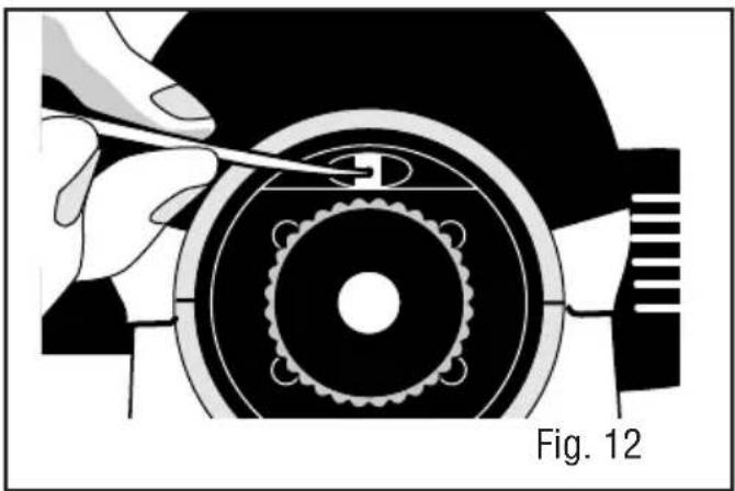
Because the instrument is set halfway between A and B, any error in the line-of-sight causes both readings to be erroneous by the same amount. Error “e” cancels out, so the value a1 - b1 = H is correct. Therefore, a2 - H = b3, the adjusting value. To adjust, unscrew the eyepiece cover. Turn the adjusting screw with the adjusting pin (Fig. 12) until the horizontal cross hair gives the reading b3, on rod B. Repeat the above Procedure until {(a1-b1) - (a2-b2)} < / = 3 mm.
Maintenance and Service

WARNING
Care must be taken to maintain the accuracy
of the instrument.
After each use, the instrument should be wiped clean and kept in its carrying case.
Remove dust from the lenses with a soft brush or a nonabrasive wipe. Never touch the lenses with your fingers.
Store the instrument in a dust-free area with low humidity.
A bag of silica gel dryer is included with each instrument; if it has stopped working effectively, bake it to remove moisture or replace with a new bag.
If the tool should fail despite the care taken in manufacturing and testing
procedures, repair should be carried out by an authorized after-sales service center for Bosch measuring tools.
In all correspondence and spare parts orders, please always include the 10-digit article number given on the type plate of the tool. In case of repairs, send in the tool packed in its protective case.
ENVIRONMENT PROTECTION
Recycle raw materials & batteries instead of disposing of waste. The unit, accessories, packaging & used batteries should be sorted for
environmentally friendly recycling in accordance with the latest regulations.

LIMITED WARRANTY OF BOSCH LASER AND MEASURINGTOOLPRODUCTS
Limited Warranty Program
Robert Bosch Tool Corporation ("Seller") warrants to the original purchaser only, that all Bosch lasers and measuring tools will be free from defects in material or work-manship for a period of one (1) year from date of purchase. Bosch will extend warranty coverage to two (2) years when you register your product within eight (8) weeks after date of purchase. Product registration card must be complete and mailed to Bosch (postmarked within eight weeks after date of purchase), or you may register on-line at www.boschtools.com/Service/ProductRegistration. If you choose not to register your product, a one (1) year limited warranty will apply to your product.
30 Day Money Back Refund or Replacement -
If you are not completely satisfied with the performance of your laser and measuring tools, for any reason, you can return it to your Bosch dealer within 30 days of the date of purchase for a full refund or replacement. To obtain this 30-Day Refund or Replacement, your return must be accompanied by the original receipt for purchase of the laser or optical instrument product. A maximum of 2 returns per customer will be permitted.
SELLER'S SOLE OBLIGATION AND YOUR EXCLUSIVE REMEDY under this Limited Warranty and, to the extent permitted by law, any warranty or condition implied by law, shall be the repair or replacement of parts, without charge, which are defective in material or workmanship and which have not been misused, carelessly handled, or misrepaired by persons other than Seller or Authorized Service Center. To make a claim under this Limited Warranty, you must return the complete Bosch laser or measuring tool, transportation prepaid, to any BOSCH Factory Service Center or Authorized Service Center. Please include a dated proof of purchase with your tool. For locations of nearby service centers, please use our on-line service locator or call 1-877-267-2499.
THIS WARRANTY PROGRAM DOES NOT APPLY TO TRIPODS AND RODS. Robert Bosch Tool Corporation (“Seller”) warrants tripods and leveling rods for a period of one (1) year from date of purchase.
THIS LIMITED WARRANTY DOES NOT APPLY TO OTHER ACCESSORY ITEMS AND RELATED ITEMS. THESE ITEMS RECEIVE A 90 DAY LIMITED WARRANTY.
To make a claim under this Limited Warranty, you must return the complete product, transportation prepaid. For details to make a claim under this Limited Warranty please visit www.boschtools.com or call 1-877-267-2499.
ANY IMPLIED WARRANTIES SHALL BE LIMITED IN DURATION TO ONE YEAR FROM DATE OF PURCHASE. SOME STATES IN THE U.S., AND SOME CANADIAN PROVINCES DO NOT ALLOW LIMITATIONS ON HOW LONG AN IMPLIED WARRANTY LASTS, SO THE ABOVE LIMITATION MAY NOT APPLY TO YOU.
IN NO EVENT SHALL SELLER BE LIABLE FOR ANY INCIDENTAL OR CONSEQUENTIAL DAMAGES (INCLUDING BUT NOT LIMITED TO LIABILITY FOR LOSS OF PROFITS) ARISING FROM THE SALE OR USE OF THIS PRODUCT. SOME STATES IN THE U.S., AND SOME CANADIAN PROVINCES DO NOT ALLOW THE EXCLUSION OR LIMITATION OF INCIDENTAL OR CONSEQUENTIAL DAMAGES, SO THE ABOVE LIMITATION MAY NOT APPLY TO YOU.
THIS LIMITED WARRANTY GIVES YOU SPECIFIC LEGAL RIGHTS, AND YOU MAY ALSO HAVE OTHER RIGHTS WHICH VARY FROM STATE TO STATE IN THE U.S., OR PROVINCE TO PROVINCE IN CANADA AND FROM COUNTRY TO COUNTRY.
THIS LIMITED WARRANTY APPLIES ONLY TO PRODUCTS SOLD WITHIN THE UNITED STATES OF AMERICA, CANADA AND THE COMMONWEALTH OF PUERTO RICO. FOR WARRANTY COVERAGE WITHIN OTHER COUNTRIES, CONTACT YOUR LOCAL BOSCH DEALER OR IMPORTER.
© Robert Bosch Tool Corporation 1800 W. Central Road Mt. Prospect, IL 60056-2230
Exportado por: Robert Bosch Tool Corporation Mt. Prospect, IL 60056-2230, E.U.A.