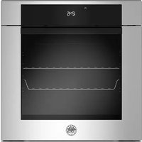
F6011MODVLXC - Oven BERTAZZONI - Free user manual and instructions
Find the device manual for free F6011MODVLXC BERTAZZONI in PDF.


| Brand | Bertazzoni |
| Model | F6011MODVLXC |
| Product type | Steam built-in oven |
| Power supply | 220-240 V, 50 Hz, 2800 W, 13 A |
| Cable cross-section | 3 x 1.5 mm² |
| Main functions | Convection, Fan-assisted, Static, Fast preheat, Turbo, Bottom heat, Grill, Convection grill, Assistant, Specific functions (dehydration, defrosting, heating, proving, Sabbath, Eco), Steam with 3 levels (Min, Med, Max) |
| Cleaning | Pyrolysis (120 min), Eco pyro, Hydroclean (20 min) |
| Display | Touchscreen |
| Controls | 2 buttons or Full Touch depending on version |
| Temperature probe | Yes, removable |
| Lighting | Halogen bulb G9 220V 40W |
| Water tank | Removable, capacity not specified, cold water only |
| Cooking levels | 5 levels |
| Supplied accessories | Grills, trays, perforated tray, temperature probe, telescopic guides (optional) |
| Safety | Door locking during pyrolysis, automatic shutdown when door opens, overheat protection |
| Maintenance | Regular manual cleaning, periodic descaling required, replacement of tank seals |
| Repairability | Spare parts available through authorized service (bulb, seals, probe) |
| General information | Domestic use, built-in, Italian manufacture, CE standards |
Frequently Asked Questions - F6011MODVLXC BERTAZZONI
User questions about F6011MODVLXC BERTAZZONI
0 question about this device. Answer the ones you know or ask your own.
Ask a new question about this device
Download the instructions for your Oven in PDF format for free! Find your manual F6011MODVLXC - BERTAZZONI and take your electronic device back in hand. On this page are published all the documents necessary for the use of your device. F6011MODVLXC by BERTAZZONI.
USER MANUAL F6011MODVLXC BERTAZZONI
INSTALLATION AND USER MANUAL BUILT-IN STEAM OVENS
HANDLEIDING VOOR INSTALLATIE EN GEBRUIK INBOUW STOOMOVENS
INSTRUKTIONER FÖR INSTALLATION OCH ANVÄNDNING ÅNGUGNAR FÖR INBYGGNAD
INSTRUCTIONS D'INSTALLATION ET D'UTILISATION FOURS ENCASTRABLES À VAPEUR

INDICE

AVVERTENZE 4
RESPONSABILITÀ DEL PRODUTTORE 4
TUTELA DELL'AMBIENTE 4
IMBALLI IN PLASTICA 4
natural_image
Simple line drawing of a rectangular frame with two vertical arrows and labels 't' at the bottom (no text or symbols on the frame itself)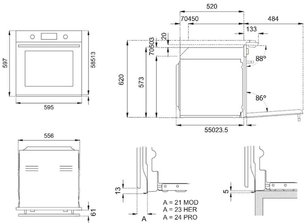
MANUALE TECNICO PER L'INSTALLATORE

natural_image
Technical line drawing of a screwdriver inserted into a mechanical component (no text or symbols)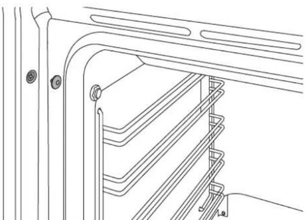
natural_image
Technical line drawing of a mechanical or architectural component with layered structure and mounting holes (no text or symbols)natural_image
Diagram of a cable with labeled components L and N, showing a hanging object and ground level (no text or symbols beyond labels)natural_image
Simple geometric diagram with a rectangle inside a rectangle and the number 1 below (no text or symbols within the shapes)natural_image
Diagram of a refrigerator interior showing door, drawer, and drawer with rotation arrows indicating movement (no text or symbols)natural_image
Technical illustration of a mechanical component with internal channels and a top plate, showing an upward arrow (no text or symbols)natural_image
Technical line drawing of a mechanical assembly with an arrow indicating rotation (no text or symbols)TABELLA INDICATIVA PER LA COTTURA
natural_image
Technical line drawing of a door frame with a horizontal shelf and two black arrows indicating movement or force directions (no text or symbols present)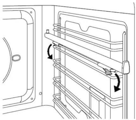
natural_image
Technical line drawing of a door frame with horizontal metal racks and directional arrows indicating movement (no text or symbols)natural_image
Technical diagram of a mechanical assembly with directional arrows indicating movement or force (no text or symbols present)
PULIZIA DELL'APPARECCHIO

natural_image
Technical line drawing of a multi-panel rack or storage unit with directional arrows indicating movement (no text or symbols)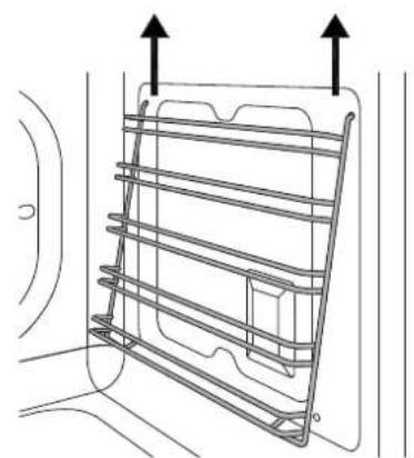
natural_image
Technical line drawing of a metal rack structure with two upward arrows indicating top and bottom directions (no text or symbols)natural_image
Technical line drawing of two mechanical components mounted on a panel, showing mounting and mounting details (no text or symbols)natural_image
Technical line drawing of a mechanical component with a magnified inset showing internal components (no text or symbols)PULIZIA VETRI INTERNI PORTA FORNO

natural_image
Technical line drawing of a door frame and door lock assembly (no text or symbols)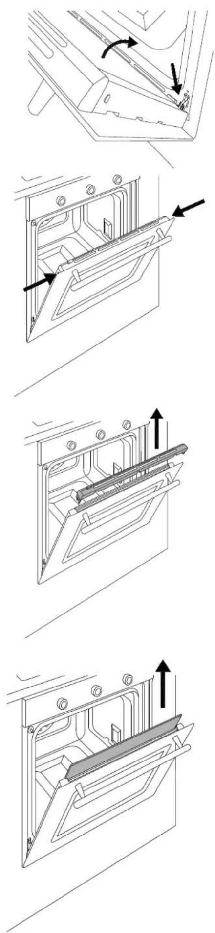
natural_image
Technical line drawings of a mechanical assembly with multiple views and directional arrows (no text or symbols)MALFUNZIONAMENTO
INSTALLATION AND USER MANUAL BUILT-IN STEAM OVENS


CONTENTS
INTRODUCTION AND WARNINGS 4
MANUFACTURER LIABILITY 4
ENVIRONMENTAL PROTECTION 4
PLASTIC PACKAGING 4
APPLIANCE DATA PLATE 4
GENERAL SAFETY INSTRUCTIONS 5
USAGE INSTRUCTIONS 6
APPLIANCE WARNINGS 6
TECHNICAL INSTALLATION INSTRUCTIONS 7
INSTALLING THE OVEN IN THE UNIT 7
IMPORTANT INFORMATION 7
INSTALLING THE OVEN BELOW A HOB 8
INSTALLING THE OVEN IN A TALL APPLIANCE HOUSING 8
OVEN FASTENING 9
ELECTRICAL CONNECTION 9
MAINTENANCE 10
REPLACING COMPONENTS 10
USING THE APPLIANCE 11
CONTROL PANEL 11
TWO-KNOB OVEN CONTROLS 11
FULL-TOUCH OVEN CONTROLS 11
OVEN FUNCTIONS 11
FIRST USE 12
BEFORE FIRST USE 12
RACK POSITIONING 12
COOLING 12
PRE-HEATING 12
OVEN LIGHT 12
WATER HARDNESS 12
USING TWO-KNOB OVENS 13
CLEANING THE APPLIANCE 24
BASIC MAINTENANCE 25
REMOVING THE SIDE GUIDES 25
REPLACING THE OVEN LIGHT BULB 25
REPLACING RESERVOIR SEAL 25
CLEANING THE INTERNAL DOOR GLASS 26
TROUBLESHOOTING 27
WARRANTY 27

FROM THE DESK OF OUR PRESIDENT
Dear Customer,
Thank you for choosing a quality Bertazzoni appliance for your home.
It was way back in 1882 that my family began manufacturing cookers, and our company has since built up a solid reputation for the excellence of its engineering, born of a passion for good food.
Today, our products feature exclusive Italian design combined with the latest technology. Our mission is to build domestic appliances which work perfectly and fully meet the requirements of their users.
To create products of the highest quality also in aesthetic terms, which meet all of our customers' requirements. Our appliances are also versatile and easy to use, turning the potential chore of cooking into a genuine pleasure.
This manual will help you to use and take care of your Bertazzoni product in the safest and most efficient manner, so that it can provide you with the utmost satisfaction for many years to come.
I really hope you like it!
Paolo Bertazzoni
President
INTRODUCTION
READ THESE INSTRUCTIONS CAREFULLY BEFORE INSTALLING AND USING THE APPLIANCE.
These instructions are valid only for the countries whose identifying symbols are included on the cover of this manual and on the appliance label. The manufacturer shall not be held liable for property damage or personal injury resulting from incorrect installation or improper use of the appliance.
The manufacturer shall also not be held liable for any imprecisions due to printing or transcription errors in this booklet.
The appearance of the fi gures included herein is only for guidance.
The manufacturer reserves the right to make modifications to its products when it considers this necessary or beneficial, however the essential safety and performance characteristics shall not be affected.
THIS APPLIANCE IS DESIGNED FOR NON-PROFESSIONAL, DOMESTIC USE.
This user manual is an integral part of the appliance and must therefore be kept in its entirety in a place accessible to the user for the entire lifetime of the appliance.
Read this manual before using the appliance.
MANUFACTURER LIABILITY
The manufacturer shall bear no liability for property damage or personal injury due to:
• Use of the appliance other than that specified.
- Failure to comply with the instructions in the user manual.
- Tampering with/unauthorised modifications to any part of the appliance.
• The use of non-original spare parts.
- This appliance is intended for cooking food in the home environment. Any other use shall be considered improper.
- The appliance is not designed to operate with external timers or with remote-control systems.
WARNING: The € marking on this product is a declaration, under the manufacturer's full responsibility, that the product complies with all European health, safety and environmental requirements laid out in the legislation covering this product type.
ENVIRONMENTAL PROTECTION

Please think of the environment when disposing of the packaging.
This appliance is marked in accordance with European Community Directive 2012/19/EU on waste electrical and electronic equipment (WEEE).
This directive defines the standards for the collection and recycling of waste electrical and electronic equipment applicable throughout the European Union.
The packaging of this appliance is composed of the elements strictly necessary to ensure sufficient protection during transport. The packaging materials are completely recyclable, thus reducing their environmental impact. Please help to protect the environment by taking the following tips into consideration:
- Sort the packaging materials for recycling.
- Render the old appliance unusable before taking it to the collection facility. Ask the competent local authorities for details of the nearest recycling centre you can take the old appliance to.
- Do not dispose of used oil down the drain. Keep it in a closed container and take it to a recycling centre; if this is not possible, dispose of it in mixed waste (in this manner it will be disposed of at a monitored facility – although this is not the best solution, it at least prevents contamination of the sewage/water systems).
PLASTIC PACKAGING
Danger of suff ocation
- Do not leave the packaging or any part thereof unattended.
- Do not let children play with the plastic bags.
APPLIANCE DATA PLATE
The data plate bears the technical data, serial number and brand name of the appliance. The appliance data plate is located on the side of the front of the oven, and must not be removed at any time. A copy is provided in this manual for reference.
INTRODUCTION
GENERAL SAFETY INSTRUCTIONS
- During use, the appliance and its accessible parts become very hot.
- Do not operate the appliance with wet hands or when it is in contact with water.
- Never touch the heating elements during use.
- Keep children under the age of eight at a safe distance unless they are constantly supervised.
• Children must not play with the appliance. - This appliance may only be used by children over the age of eight, and by people with reduced physical, sensory or mental capacity, or lacking in experience in the use of electrical appliances, provided that they are supervised or instructed by adults who are responsible for their safety.
- Keep children and animals away from the appliance while it is running or cooling down. Accessible parts become red hot during use.
- Switch off the appliance after use.
- Cleaning and maintenance must not be carried out by children without adequate supervision.
- Ensure that hot surfaces are allowed to cool before proceeding to clean the appliance.
- Have installation and servicing carried out by qualified personnel in compliance with applicable standards and legislation. Do not try to repair the appliance yourself or without the assistance of a qualified technician.
- Do not modify this appliance.
- Do not insert anything in the slots.
- Do not obstruct ventilation openings and heat dispersal slots.
- If the power supply cable is damaged, contact technical support immediately and they will arrange for it to be replaced.
- Do not use abrasive or corrosive detergents (e.g. scouring powders, stain removers and metallic sponges) on glass parts.
- Do not sit or put any weight on the oven door.
- Do not use steam jets to clean the appliance.
- Do not use the appliance as a space heater for any reason.
- In the event of breakage or cracking in the glass, shut off the oven immediately and disconnect it from the power supply. Contact technical support.
- Sudden and extreme changes in temperature can cause the glass to break – never pour cold liquids onto the oven door.
- Using the oven generates heat and moisture – keep the area well ventilated during operation.
- Never place fl ammable objects in the oven
- Do not open the door if smoke is coming
out of the oven. Shut the appliance off and disconnect its power supply.

- The oven contains electronic components which could interact with electronic medical equipment such as pacemakers or insulin pumps. Equipment of this type must be kept at least 10 cm from the oven.
- Ensure that there are no trapped objects which could prevent the oven door from shutting.
- The oven is not designed to operate with timers or remote control systems.
- Plastic containers not designed for high temperatures could melt, damaging the oven or even catching fire.
- Closed tins and jars could burst or even explode if heated: never use the oven for preparing or heating tins or jars.
- Always use specific oven gloves for removing or inserting heat-resistant cookware or accessories.
- Isolate the appliance's power supply before performing any maintenance.
- Use only the recommended temperature probe for this appliance.
INTRODUCTION
INSTRUCTIONS FOR USE

• Take great care when cooking food with a high alcohol content, as this could cause a fi re.
- Remove any food residue from inside the oven before using the appliance in order to prevent fi res and smoking.
- Do not place any objects or baking paper on the bottom of the oven.
• After cooking, keep the door closed while the oven is cooling down to prevent damaging adjacent kitchen units.
- Fruit juice can cause indelible staining; use deep dishes to prevent leakage.
- Damaged containers, or those which are unsuitably small, can lead to serious injuries.
- When opening the oven door, be very careful of escaping steam: burn hazard! Note that at high temperatures, steam is not visible.
- Do not pour water into a hot oven: this would create steam, and thus a burn hazard!
- Keep the door seal clean to prevent heat escaping and damaging adjacent units.
- Insert oven racks and trays all the way into their guides to prevent damage to the door when closing.
- Do not apply pressure to the open door.
- Do not use the appliance as a work surface or shelf.
- Open the door with care. The use of ingredients containing alcohol can create a mixture of air and alcohol.
- Avoid creating sparks or naked flames near the oven when opening the door.
- Do not place or store flammable objects or those which could ignite easily on the appliance, inside it or in its immediate vicinity.
- Empty the water reservoir each time the steam function is used. Otherwise, water left in the reservoir could overheat during subsequent use of the appliance.
• After operation with significant quantities of steam, dry the oven cavity with a soft cloth.
- Use only heat- and steam-resistant containers. Silicone moulds are not recommended for combination steam cooking.
- For steam cooking, always insert the tray to ensure that any liquid is collected.
- Fill the reservoir only with cold water: use of hot water could damage the pump.
APPLIANCE WARNINGS
- Do not place heat-resistant cookware or other objects directly onto the oven's interior surface.
- Do not place sheets of aluminium foil directly onto the oven's interior surface.
- Do not place water directly inside the hot oven.
- Do not store moist dishes and food inside the oven after completing cooking.
• Take care when removing or inserting accessories. - Any discolouration of the enamel will not affect the oven's performance.
- For very wet cake batters, use a dripping pan. Fruit juice can cause permanent stains.
- The oven is designed only for cooking. It must not be used for other purposes, such as space heating.
TECHNICAL INSTALLATION INSTRUCTIONS
The installation, adjustments, transformations and maintenance listed in this section must only be performed by qualified technicians (in accordance with applicable legislation). Incorrect installation can cause property damage and injury to people or pets; the manufacturer shall not be held liable in this event. The appliance's automatic regulation or safety devices may only be modified by the manufacturer or a duly authorised supplier during the appliance's lifetime.
Ensure all necessary PPE is used when carrying out the installation
INSTALLING THE OVEN IN THE UNIT
Ensure that the oven is fully present and undamaged after removing all loose parts from their inner and outer packaging. In the event of any uncertainty, do not use the appliance and contact technical support.
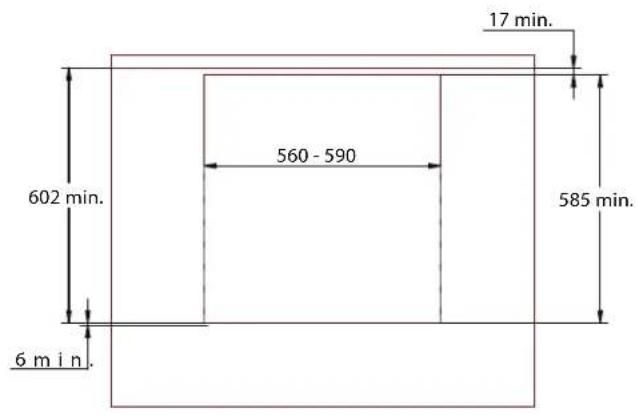
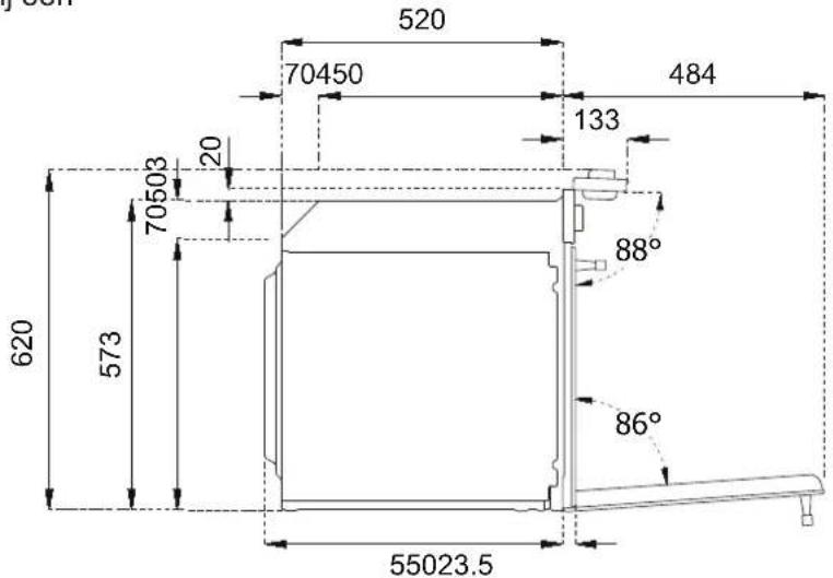
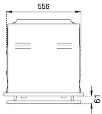
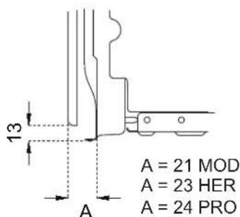
Check that the kitchen unit is suitable for installation of the oven, referring to the dimensions given in this guide.
The steam oven must be installed completely level and plumb, otherwise its operation may be compromised.
IMPORTANT INFORMATION
The oven is only suitable for installation inside a fitted kitchen unit or carcase. The sides and surrounding surfaces must be able to withstand temperatures of up to 90°C.
Installation of the appliance must be performed in accordance with the provisions of applicable legislation.
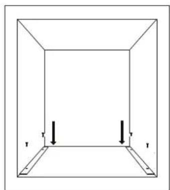
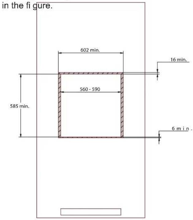
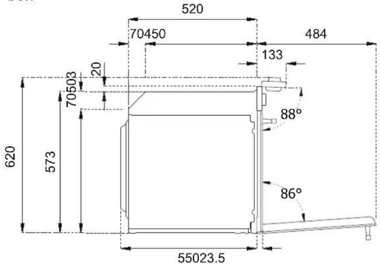
Provide for an opening in the rear of the carcase to allow for oven ventilation, as shown in the figure. Lack of sufficient ventilation could compromise oven performance.
Use the supplied brackets to attach to the carcase (one bracket per side, see figure below).
natural_image
Simple line drawing of a 3D rectangular box with two vertical arrows labeled 'r' pointing downward (no text or symbols beyond the arrow)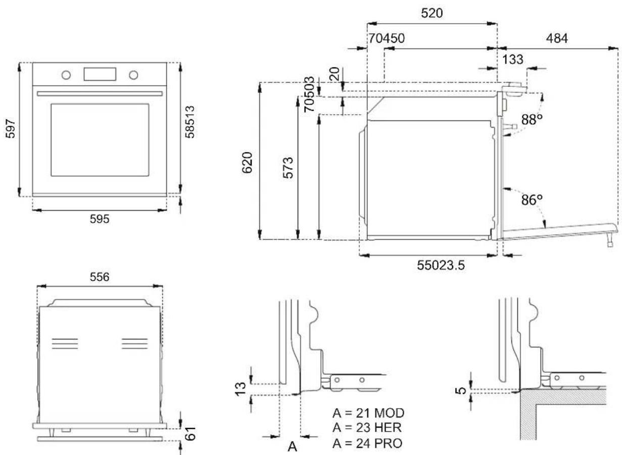
TECHNICAL INSTALLATION INSTRUCTIONS
INSTALLATION UNDERNEATH A BUILT-IN HOB
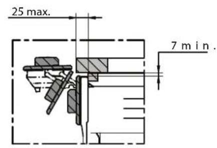
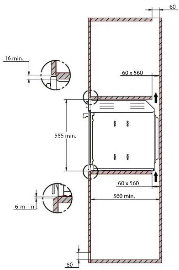
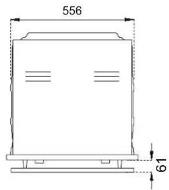
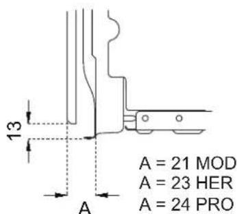
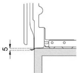
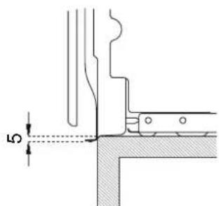
The clearance between the oven and the kitchen units or other installed appliances must be enough to ensure sufficient ventilation and air discharge. If installed under a hob, space must be left between the bottom of the hob and the top of the oven to allow for ventilation of the entire compartment (see figure).
Any ventilation openings required for the hob are to be added to those required by the oven.
The manufacturer shall bear no liability in the event of the oven being installed in combination with a hob from another manufacturer.
INSTALLING THE OVEN IN A TALL APPLIANCE HOUSING
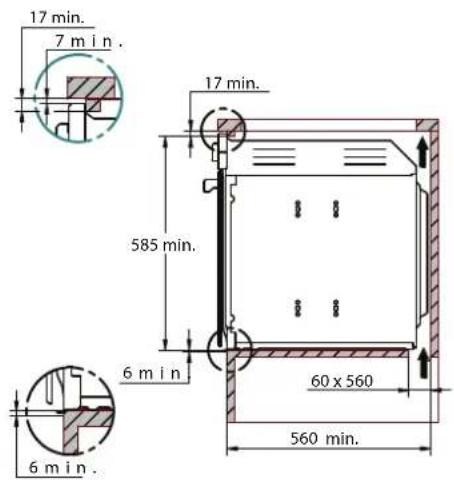
The clearance between the oven and the kitchen units must be enough to ensure sufficient ventilation and air discharge. Ensure there is an opening in the top or rear of the carcase as shown
OVEN FASTENING
- Position the appliance into the carcase with the help of a second person.
- Do not use the door or handle to position the oven.
- Check that the oven is correctly aligned with the units.
- Check that the door opens correctly.
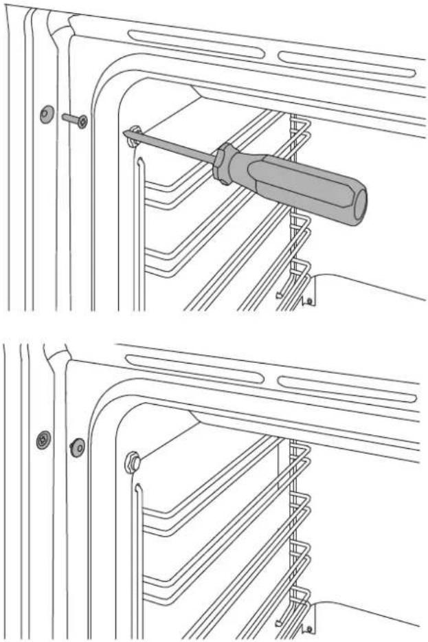
- Fasten the oven to the carcase with the supplied screws, ensuring that the oven remains centred.
• Cover the screws with the caps.
natural_image
Technical line drawing showing two views of a screwdriver inserted into a rack structure (no text or symbols)ELECTRICAL CONNECTION
The electrical connection must be made in accordance with applicable standards and legislation.
Before connecting up the appliance, check that:
- The mains electricity supply matches the characteristics indicated on the appliance data plate (positioned on the front of the oven).
- The circuit wiring and outlet are equipped with a compliant earth connection.
Connection to the mains power supply via a socket:
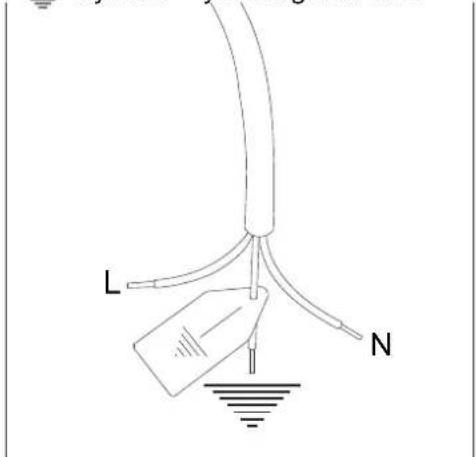
- Wire a plug onto the power cable which must comply with applicable standards in the country of use; the plug (and its fuse, where applicable) must be suitable for the rated load specified on the appliance data plate. Connect the cores of the cable in accordance with the figure, ensuring you follow the harmonised wiring colour scheme:
L (live/hot/phase) = brown wire
N (neutral) = blue wire
earth "⊥" symbol = yellow/green wire
| Voltage 220-240 V | |
| Frequency 50Hz | |
| Max. power 2800 W | |
| Max current draw | 13 A |
| Cable type 3x1.5mm ^2 |

ELECTRICAL CONNECTION
- Position the power supply cable in such a way that it is not resting against the rear of the oven, that it is not in contact with sharp edges and will not reach a temperature of 90^ at any point.
- Do not use adapters, extension leads, gang sockets etc. as these could cause loose contacts and overheat.
Hard-wired to the mains circuit:
- The circuit must be fitted with a omnipolar circuit breaker of suitable capacity for the appliance's rated load.
- The earth conductor must not be switched by the breaker and must be connected to the earthing system.
- As an alternative, an RCBO may also be used, or RCD protection in addition to or instead of a fuse or MCB, depending on the applicable electrical code.
MAINTENANCE
REPLACING COMPONENTS
Isolate the appliance's power supply before performing any maintenance.
Contact an authorised service centre if functional components require replacement.
WARNING: If the power cable requires replacement, the installer/maintenance technician must use H05VV-F cable and leave the earth conductor around 2 cm longer than the live and neutral wires. They must also comply with the instructions given for the initial electrical connection.

CONTROL PANEL
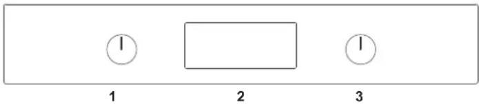
TWO-KNOB OVEN CONTROLS
1 Function selector
2 Touchscreen display
3 Temperature selector
| TIME FUNCTIONS time menu | ||
| RETURN TO PREVIOUS MENU return to the previous menu and scroll | ||
| OK | CONFIRM confi rm or continue | |
| MOVING AROUND THE MENU modifi es the quantities or scrolls the menu |
FULL-TOUCH OVEN CONTROLS
1 Touchscreen display
N.B.: for temperature settings and functions, touch the icon on the display.

natural_image
Simple geometric shape: a rectangle inside a rectangle (no text or symbols)1
| ON/OFF turns the oven on or off | ||
| MOVING AROUND THE MENU reduces the quantities or scrolls the menu | ||
| TIME FUNCTIONS time menu | ||
| RETURN TO PREVIOUS MENU returns to the previous menu | ||
| MOVING AROUND THE MENU | increases the quantities or scrolls the menu | |
| OK | CONFIRM confi rm or continue | |
OVEN FUNCTIONS
| SYMBOL DESCRIPTION | PTION 11 FUNCTIONS 11 PYROLYTIC | FUNCTION | |
| Convection · | · | ||
| Fan | · | ||
| Static | · | ||
| Fast Preheat | · | ||
| Turbo | · | ||
| Bottom Bake | · | ||
| Grill | · | ||
| Fan with grill | · | ||
| Assistant | · | ||
| Specials | · | ||
| Hydroclean · | |||
| Clean | |||

USE
Run your finger up and down the display to scroll through the menu.
To activate a menu function, press and hold the required function for at least two seconds. The chosen function will be selected as soon as you remove your fi nger from the display.
FIRST USE
Once the oven has been connected to the power supply, enter the settings menu (see settings chapter) and set the following:
- Language
- Clock
- Clock Format
• Measurement Units
BEFORE FIRST USE
- Remove any film and other packaging residue from the inside and outside of the oven.
- Remove and wash all accessories.
- Run the oven for 30 min. at 250^ without placing any food inside (during this operation it is normal for manufacturing residue to produce some smoke and odours).
- Let the oven cool down.
- Open the door and air the oven out for 15 minutes.
- Clean the inside of the oven with a moist cloth and neutral detergent (do not use scouring powders).
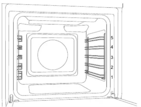
RACK POSITIONING
Insert racks and trays into the side guides until they come to a complete stop in order to prevent contact with the oven door.
When removing accessories beyond halfway they are blocked to facilitate removing dishes.
The oven has fi ve cooking levels indicated on the right-hand side of the front of the oven.
natural_image
Technical line drawing of a door with internal compartments and numbered parts (1-5), no text or symbols present.COOLING
The oven is equipped with a cooling system which operates during cooking.
Air flow between the control panel and door allows the controls to be kept at a usable temperature.
The cooling system turns on and off automatically (it is normal for this to continue running after the oven is switched off).
PRE-HEATING
Most recipes will require the dish to be placed in the oven when it has already reached the specified cooking temperature.
The pre-heating time will depend on the temperature set and the number of accessories present in the oven.
OVEN LIGHT
The oven light comes on automatically when the door is opened and remains on during standard cooking functions.
WATER HARDNESS
Do not use distilled water or tap water with a high chlorine content (> 40 mg/l), or other liquids.
- Use only cold, clean tap water.
- If the water in your area is very hard, use softened water or mineral water.
- Do not use sparking water.
- Do not use water with hardness dH > 7 (1.3 mmol/l).
USE
USING TWO-KNOB OVENS
- Insert the rack at the required level
- Select the oven function by rotating the knob
- Set the temperature by turning the knob clockwise
- If necessary, set timed cooking.
An audible warning and visual message indicate when the set temperature is reached.
Return at least one knob to the zero position at any time to stop cooking
To select the functions, touch the icons at the sides of the display and hold for at least two seconds. The chosen function will be selected as soon as you remove your finger. The symbols for the available commands light up on each screen
- Insert the rack at the required level
- Select the required function using the + and - buttons and confirm by pressing the OK button
- Select the required temperature using the + and - buttons and confi rm by pressing the OK button
- If required, set timed cooking by touching the Clock button.
- Touch the OK button to start cooking, or wait (5 seconds) for it to start automatically.
An audible warning and visual message indicate when the set temperature is reached.
Touch the power button at any time to stop cooking.
COOKING MODES
The oven is equipped with various heating elements which create the various cooking modes when activated individually or in combination.
Warning: all cooking operations must take place with the door closed.
Convection
Heat from the rear element with fan assist.
Cooking on multiple levels, ideal for any type of food which requires even heat.
• Level 2 or 3 for cooking single items.
• Levels 2 and 4 for cooking multiple items.
Possible addition of steam (min-med-max levels).
Fan
Heat from above and below with fan assist.
Cooking on multiple levels: ideal for biscuits and cakes.
• Level 2 or 3 for cooking single items.
• Levels 2 and 4 for cooking multiple items.
Possible addition of steam (min-med-max levels).
Static
Heat from above and below.
Cooking on a single level: ideal for roasts, bread and cakes.
• Roasts: level 2 or 3.
- Cakes: level 2 or 3 to ensure correct cooking of the bottom without burning the top.
Fast Preheat
Use this function to bring the oven to the required temperature in a short period of time.
This function is designed only for heating the oven, and not for cooking food.
Turbo
Combination function: convection and bottom element.
Cooking on a single level, ideal for pizza, flatbreads and other foods requiring high temperatures and heat from below.
- Level 1 or 2.
Possible addition of steam (min-med-max levels).
Bottom Bake
Heat from below.
Cooking on a single level, ideal for slow cooking and for heating plates.
At high temperatures, use this function for baked goods which you do not wish to brown.
- Level 2 or 3.
USE
Grill
Heat from the grill (broiler) element.Max
recommended temperature: 200°C.
Cooking on a single level, ideal for grilling sausages, chops, bacon, fi sh or toast.
Browning or gratinating food at the end of cooking.
- Level 4 or 5.
Fan with grill
Heat from the grill (broiler) element with fan assist.
Max recommended temperature 175°C.
Cooking on a single level, ideal for grilling thick foods.
The circulation of the heat aids optimum cooking of the food while grilling from above.
- Level 4 or 5.
Possible addition of steam (min-med-max levels).
Assistant
see specifi c chapter
Specials
Dehydrate
Function with forced air circulation and a temperature of 37^ C for drying foods, flowers and vegetables.
Defrost
Function with forced air circulation to speed up defrosting of foodstuff s.
Warming
Function for warming up food; three temperature levels: 60^ C - 76^ C - 93^ C.
Proofing
Function for leavening dough. It is recommended to insert the foodstuff s with the oven still cold.
Do not open the oven unless strictly necessary.
Sabbath
Heating method for use during periods of religious observance.
Eco
Fan-assisted cooking function with low power consumption (light deactivated during cooking).
Settings
See specific chapter
USE
Cleaning (only eleven-function pyrolytic oven)
Pyro
In the self-cleaning cycle, the oven's interior is heated to very high temperatures – over 400^ C – to burn off any food residue.
Before starting a pyrolysis cycle, remove all accessories, the side racks and the water reservoir from the oven, then manually remove any pieces of food and larger residues with a damp sponge.
Remove the silicone cap from the temperature probe socket and insert the metal cap.
During pyrolysis, the door locks automatically and will only reopen when the oven cools back down at the end of the cycle.
It is normal to see some flaming and smoke develop inside the oven.
After the cleaning cycle, the burned off residue is reduced to ash and can be easily brushed off with a damp sponge.
The complete cycle duration is 120 minutes.
Eco Pyro
Ninety-minute self-cleaning cycle which can be used when there are lower levels of encrusted dirt.
Hydroclean
Twenty-minute low-temperature oven cleaning cycle.
- Manually remove any pieces of food and larger residues with a damp sponge.
- Pour 400 ml of water onto the base inside the cavity.
- Spray a solution of water and washing-up liquid (using a spray bottle) onto the side walls.
- Activate the function (duration approx. 20min).
- Once it has cooled back down, dry with a soft cloth.
Hydroclean (eleven-function oven only)
Twenty-minute low-temperature oven cleaning cycle.
- Manually remove any pieces of food and larger residues with a damp sponge.
- Pour 400 ml of water onto the base inside the cavity.
- Spray a solution of water and washing-up liquid (using a spray bottle) onto the side walls.
- Activate the function (duration approx. 20min).
- Once it has cooled back down, dry with a soft cloth.
USE
STEAM
During steam-assisted cooking
During operation of the appliance with the addition of steam, steam is dispensed inside the oven at different intervals and with various intensities.
Adjusting the steam percentage and temperature will achieve improved cooking results:
- Crunchy crust
- Shiny surface
- Soft, juicy centre
- Minimal reduction in volume
With fan-assisted functions, it is possible to select the percentage of steam to be added during cooking.
Use only heat- and corrosion-resistant cookware or food-grade stainless-steel containers.
When cooking on multiple levels, check that there is space between the different levels in order to allow the steam to circulate.
If the temperature probe is not being used during steam cooking, insert the silicone cap in the socket.
If the oven door is opened during operation, it will stop immediately. Once the door is closed, the appliance will resume operation.
To shut off the appliance in advance or adjust the set steam quantity, press the steam icon on the display.
Steam Levels
The addition of steam ensures dishes are cooked gently, keeping the interior juicy.
Three levels of steam can be selected for fan-assisted cooking programs:
- MIN. Ideal for meat, poultry and baked dishes.
• MED. Ideal for stewed/braised meat, bread and other leavened dishes.
- MAX. Ideal for delicate dishes such as custards, fl ans, timbales and fi sh.
Pump
During operation and after switching off, an audible hum indicates that the pumps are operating.
Water Reservoir
The water reservoir is located behind the control panel. Before use, open the control panel and fill the water reservoir.
If the water in the reservoir runs out during use, a buzzer will sound and a message will be displayed instructing you to top it up.
Steam Accessories
For steam cooking, use racks or perforated trays
Derivative Function
Regeneration
Delicately reheat previously cooked food, or prepare baked goods in advance.
Set fan-assisted cooking at 120^ C with the addition of Medium Steam for 7 minutes.
The time required may vary on the basis of the quantity of food or the container used.
USE
CONDENSATION
When cooking foods with a high water content, it is normal for condensation to form on the inside of the oven door and on the control panel. This condensation will evaporate by itself during cooking.
Programs with steam, due to their nature, generate condensation throughout the oven, and particularly on the inside door glass. When using steam cooking functions, particularly at low temperatures, remember to empty the drip tray.
COOKING TIPS
- The set temperature, cooking time and steam quantity may vary slightly from one oven to another. Slight adjustments to recipes may be necessary.
- Increasing the temperature does not decrease cooking times.
- Cooking times depend on the weight, thickness and quality of the food.
- When steam cooking, position foodstuffs so that they are not overlapping.
- We recommend placing the food at the centre of the rack.
- Choose the level of cooking in accordance with the recipe and personal experience.
- Leave at least 3 cm between oven dishes and the sides of the oven to allow heat to circulate.
- Use light-coloured aluminium trays when cooking pastries.
- Use dark metal tins for cooking sweets and biscuits, as they help absorb heat.
- Turn and mix dishes so that they heat through evenly.
- For new recipes, choose the lowest temperature from those given along with the shortest time; then assess how well cooked the dish is, prolonging the cooking if necessary.
- Do not open the oven door during cooking to ensure the correct moisture level for the food.
SAVING ENERGY
- Open the oven door only when necessary to avoid wasting heat.
- Keep the inside of the oven clean.
- Remove any accessories not currently being used.
- Shut off the oven a few minutes before
- the time normally used, allowing the residual heat of the oven to finish cooking.
- Let frozen foodstuff s thaw completely before placing them in the oven.
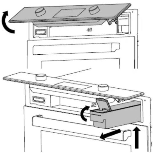
WATER RESERVOIR
The water reservoir is located behind the control panel.
After setting the function, temperature and steam quantity:
- Confirm opening of the control panel.
- Lift the panel upwards with both hands until it clicks.
- Gently lift the reservoir and pull it out partially.
- Open the lid and fill with water to the indicated level.
- Close the lid again.
- Reposition the reservoir by pushing it all the way until it locks in place.
- Lift the control panel upwards to release it, and then lower it until it is fully closed.
The water reservoir can be completely removed for cleaning or filling.
natural_image
Diagram of a kitchen appliance with rotating parts and directional arrows indicating motion (no text or symbols)It is possible to access the reservoir at any time by pressing the OK and ▶ icons simultaneously and then confirming by pressing OK on two-knob ovens, or by pressing the + and OK icons simultaneously and then confirming by pressing OK on touchscreen ovens.

USE

WARNING: each time the reservoir is removed, check that the seals are intact and correctly positioned.
For extended cooking, it may be necessary to refi ll the water: this is indicated by a buzzer sounding and message on the display.
When cooking is complete, the water in the circuit is automatically drained into the reservoir.
WARNING: The water in the reservoir may be boiling hot: check that the water has cooled down before removing the reservoir.
- Press the OK and Icons simultaneously and then confirm by pressing OK on two-knob ovens, or press the + and OK icons simultaneously and then confirm by pressing OK on touchscreen ovens.
- Lift the panel upwards with both hands until it clicks.
• Gently lift the reservoir and pull it out partially.
• Empty the reservoir, removing the lid. - Wash with soapy water and rinse thoroughly with clean water.
• Dry with a clean tea towel. - Reassemble the reservoir.
- Reposition the reservoir by pushing it all the way until it locks in place.
- Lift the control panel upwards to release it, and then lower it until it is fully closed.
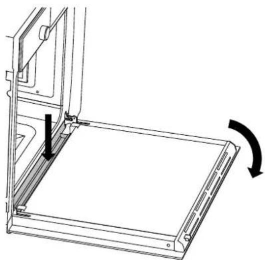
DRIP TRAY
During steam cooking, the condensation that forms on the door is collected in the drip tray.
This must be dried at the end of cooking:
- Let the oven cool down.
- Open the oven door.
- Mop up the water in the drip tray with a
- soft cloth.
natural_image
Technical line drawing of a mechanical component with an arrow indicating rotation (no text or symbols)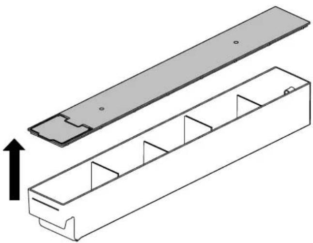
natural_image
Technical illustration of a mechanical assembly with two views: top shows a rectangular plate, bottom shows a multi-compartment housing (no text or symbols)Do not wash the reservoir in the dishwasher.
SCOOKING GUIDELINE
The times given in the table do not include preheating times and are provided only as a guide.
| Food Weight (kg) | Function Temperature (°C) Time (minutes) | |||
| Lasagne 3-4 Static 220-230 45-50 | ||||
| Baked pasta 3-4 Static 220-230 45-50 | ||||
| Roast veal 2 Fan 180-190 | 90-100 | |||
| Pork loin | 2 Fan 180-190 70-80 | |||
| Sausages | 1.5 | Fan with grill 175 | 15 | |
| Roast beef | 1 Fan | 200 | 40-45 | |
| Roast rabbit | 1.5 | Convection | 180-190 | 70-80 |
| Turkey breast | 3 Fan 180-190 110-120 | |||
| Roast pork neck | 2-3 | Fan 180-190 | 170-180 | |
| Roast chicken | 1.2 | Fan 180-190 | 65-70 | |
| 1st side 2nd side | ||||
| Pork chops | 1.5 | Fan with grill | 175 | 15 5 |
| Spare ribs | 1.5 | Fan with grill | 175 | 10 10 |
| Bacon | 0.7 | grill | 200 | 7 8 |
| Pork fillet | 1.5 | Fan with grill | 175 | 10 5 |
| Beef fillet | 1 | grill | 200 | 10 7 |
| Rainbow trout | 1.2 | Fan 150-160 | 35-40 | |
| Monkfish | 1.5 | Fan | 160 | 60-65 |
| Turbot | 1.5 | Fan | 160 | 45-50 |
| Pizza | 1 | Turbo | MAX | 8-9 |
| Bread | 1 | Convection | 190-200 25-30 | |
| Focaccia | 1 Fan 180-190 20-25 | |||
| Bundt cake | 1 | Convection | 160 | 55-60 |
| Jam tart | 1 | Convection | 160 | 35-40 |
| Ricotta cake | 1 | Convection | 160-170 55-60 | |
| Stuffed tortellini | 1 | Fan | 160 | 20-25 |
| Sponge cake | 1.2 | Convection 160 | 55-60 | |
| Profiteroles | 1.2 | Fan | 180 | 80-90 |
| Victoria sponge | 1 | Convection | 150-160 | 55-60 |
| Rice cake | 1 Fan | 160 | 55-60 | |
| Pastries | 0.6 | Convection | 160 | 30-35 |

USING THE TOUCHSCREEN DISPLAY
SETTINGS MENU

Select Settings in the Specials menu. Ⓧ Scroll through the functions using the + and - buttons
Brightness
To set or change the display brightness.
Audio
To set or change the volume of the sounds.
Language
To select the preferred appliance language (the default is English).
Clock
To set or change the time.
Showroom Mode
Deactivates the heating elements for showrooms use.
Weight Unit
To set or change the unit of measurement used for weight.
Temp Unit
To set or change the unit of measurement used for temperature.
ECO Mode
To reduce energy consumption.
USING THE TOUCHSCREEN DISPLAY
MANAGING THE TIME FUNCTIONS
The time function allows you to manage cooking times.
After setting the function and temperature, press the clock icon repeatedly (☐) and choose a time function.
Timer △
To set a countdown timer, at the end of which an audible warning will sound and a message will be displayed. The timer does not stop the cooking operation.
Scroll to set; the timer starts automatically.
Function available even with the oven not operational
Cooking Time
To set a countdown timer, at the end of which cooking will be stopped, an audible warning will sound and a message will be displayed.
Scroll to set; the cooking time timer starts automatically.
Start at Ⓤ
To set the start time and duration of cooking.
When the set time arrives, an audible warning will sound indicating the start of cooking. When the set duration has elapsed, cooking will stop, an audible warning will sound and a message will be displayed.
Scroll to set first the start time and then the cooking time.
Touch the Power button to stop cooking at any point.
Touch the clock icon to modify the duration of the current cooking program.
Important: if the time functions are not managed, the duration of the cooking must be managed manually.
TEMPERATURE PROBE (where available)
The temperature probe allows you to choose the level of cooking by measuring the internal temperature of the food.

Programming the temperature probe
- Insert the sharp end of the probe into the food. For the best results, the tip must be as close as possible to the centre point of the food, and not in contact with fat, bone or hollow areas.
- Choosing the cooking function and temperature
- Plug in the probe inside the oven (on the top left-hand side).
- Set the temperature you wish to obtain at the centre of the food.
When the set temperature is measured by the probe, cooking will stop, an audible warning will sound and a message will be displayed.
If the temperature probe is not being used during steam cooking, insert the silicone cap in the socket.
During pyrolysis, insert the metal cap in the temperature probe socket.
Important: when using the temperature probe, only the Timer function is available.
USING THE TOUCHSCREEN DISPLAY
ASSISTANT
The assistant function helps you manage a range of cooking, temperature and time functions for each type of food.
The system does not provide recipes, but helps the oven get the best out of yours.
- Choose the required food category.
meat, chicken, fi sh, cake, bread, pizza, pasta, vegetables
- Select the required recipe.
- Press OK.
At the end of cooking, an audible warning will sound and a message will be displayed.
To stop cooking, press the power button.
| Food Category Recipe Programme Minimum | Weight | Level of Cooking | Recommended Shelf Level | ||
| MEAT ROAST BEEF M1 1.8 KG | Medium 2 | ||||
| BEEF STEW | M2 1.8 KG | Well Done | 2 | ||
| ROAST VEAL | M3 1.8 KG Medium 2 | ||||
| ROAST PORK | M4 1.8 KG Medium 2 | ||||
| HAM HOCK | M5 | 1 KG | Well Done | 2 | |
| LEG OF LAMB | M6 1.8 KG | Well Done | 2 | ||
| LAMB CHOPS | M7 | 30/40 G EACH | Well Done | 2 | |
| POULTRY | ROAST CHICKEN | C1 | 1.5 KG | Well Done | 2 |
| CHICKEN THIGHS | C2 | 100 G EACH | Well Done | 2 | |
| DUCK | C3 | 2.3 KG | Well Done | 2 | |
| ROAST TURKEY BREAST | C4 | 600 G | Well Done | 2 | |
| ROAST TURKEY THIGHS | C5 | 1.5 KG | Well Done | 2 | |
| FISH | BAKED TUNA STEAK | F1 | 1 KG | Well Done | 2 |
| BAKED SALMON | F2 | 1 KG | Well Done | 2 | |
| BAKED BREAM | F3 | 800 G | Well Done | 2 | |
| ROAST BASS | F4 | 1.5 KG | Well Done | 2 | |
| COD FILLET | F5 | 400 G | Well Done | 2 | |
| DESSERTS | VICTORIA SPONGE | D1 | 400 G | Well Done | 2 |
| SHORTCRUST TARTS | D2 | 20 G Well Done | 2 | ||
| PASTRIES | D3 | 20 G Well Done | 2 | ||
| SHORTBREAD BISCUITS | D4 | 20 G Well Done | 2 | ||
| BREAD | BREAD | B1 | 1.2 KG | Well Done | 2 |
| BREAD ROLLS | B2 | 50/60 G | Well Done | 2 | |
| FOCACCIA | B3 | 1 TRAY | Well Done | 2 | |
| BREADSTICKS | B4 | Well Done | 2 | ||
| PIZZA | PIZZA LEV1 | PIZZA1 | 250 | Well Done | 2 |
| PIZZA LEV2 | PIZZA2 | 250 | Well Done | 2 | |
| PIZZA LEV1 (FROZEN) | PIZZA3 | 250 | Well Done | 2 | |
| PIZZA LEV2 (FROZEN) | PIZZA4 | 250 | Well Done | 2 | |
| PASTA | GRATINATED (FROZEN) | P1 | Well Done | 2 | |
| CRATINATED (FRESH) | P2 | Well Done | 2 | ||
| VEGETABLES | STEWED POTATOES | V1 | 500 | Well Done | 2 |
| BAKED POTATOES | V2 | 500 | Well Done | 2 | |
| ROAST POTATOES | V3 | 500 | Well Done | 2 | |
| STEWED ROOT VEGETABLES | V4 | 250 | Well Done | 2 | |
| STEWED PEPPERS | V5 | 250 | Well Done | 2 | |
| ROAST PEPPERS | V6 | 250 | Well Done | 2 | |
| GRILLED AUBERGINE | V7 | 250 | Well Done | 2 | |
| STEWED CAULIFLOWER | V8 | 250 | Well Done | 2 | |
| GRILLED CAULIFLOWER | V9 | 250 | Well Done | 2 | |
| STEWED BEANS | V10 | 250 | Well Done | 2 | |
| STEWED PEAS | V11 | 250 | Well Done | 2 | |

ACCESSORIES / OPTIONAL EXTRASACCESSORIES / OPTIONAL EXTRA
TELESCOPIC RAILS
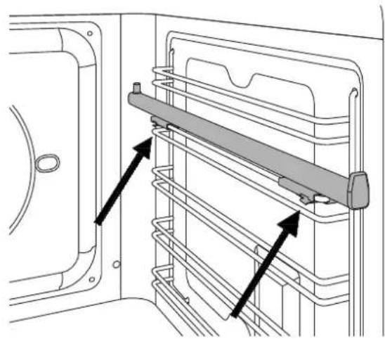
The telescopic rails can be installed on any level of the oven guides
- Locate the two spring clips (front and rear) on the telescopic rail.
- Locate the pin indicating the rear part of the rail.
- Position the telescopic rail flush with the upper edge of the selected level.
- Insert the front clip, pushing it towards the side guide.
- Insert the rear clip, pushing it towards the side guide.
- Repeat the insertion operation for the other side.
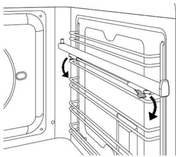
- Pull both rails out and position the oven rack or tray between the rear pin and the front stop.
natural_image
Technical line drawing of a door frame with a horizontal shelf and two black arrows indicating movement or assembly (no text or symbols)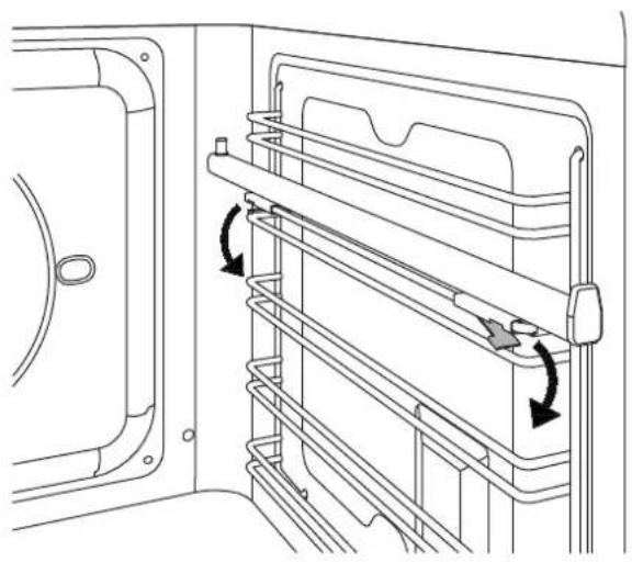
natural_image
Technical line drawing of a door frame with horizontal shelves and directional arrows indicating movement (no text or symbols)Removing the Telescopic Rails
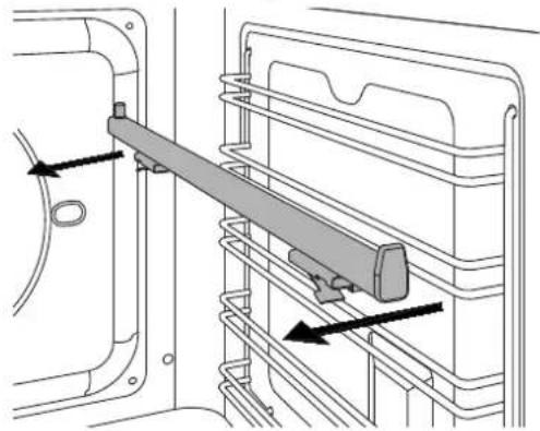
- Locate the two spring clips (front and rear) on the telescopic rail.
- Keeping the front clip pushed down, pull the rail towards the interior of the oven.
- Repeat for the rear clip.
natural_image
Technical diagram of a mechanical assembly with arrows indicating force or movement (no text or symbols present)
CLEANING THE APPLIANCE

Before performing any manual cleaning operation, wait for all parts to cool down and isolate the oven from the electrical supply.
Scrupulous care of your oven will help keep it in excellent condition for many years to come.
Cleaning enamelled or painted parts:
To maintain the characteristics of the enamelled components, they should be cleaned frequently with soapy water. Never use scouring powders. Do not leave acidic or basic substances (vinegar, lemon juice, salt, tomato juice etc.) sitting on enamelled parts, and do not wash enamelled parts when they are still hot.
Cleaning Stainless-Steel Parts:
Clean the components with soapy water and then dry them with a soft cloth, following the direction of the brushed fi nish. The shine can be maintained by periodic use of commonly available products. Do not use harsh/aggressive detergents such as:
- Limescale removers
- Bleach
- Hydrochloric acid
- Ammonia
- Scouring pads or powders
Immediately remove limescale, grease, starch or egg-white stains.
Cleaning the Door Glazing:
To degrease, use washing-up liquid and vinegar, then rinse; otherwise, clean with washing-up liquid, rinse, then pass over with a moist cloth before drying.
To remove encrusted food, soak with soapy water or washing-up liquid for a few minutes. After a few minutes, rinse off then dry with a soft cloth.
Avoid anti-limescale, abrasive and multi-purpose products, as they will affect the look of the glass after a while.
Cleaning the Oven Racks:
Do not wash the racks in the dishwasher.
Immerse them in hot soapy water, then wipe with a non-abrasive sponge before rinsing and drying with a tea towel.
Cleaning Handles:
Clean the components with soapy water and then dry them with a soft cloth, following the direction of the brushed fi nish. Never use scouring powders or pads.
Seal:
Wipe with a damp cloth.
Descaling
When the steam generator operates, limescale will build up in it. Clean the steam circuit in order to prevent excessive scale build-up.
Two reminders will be given to perform descaling. The first serves as a reminder, suggesting that the user run the descaling function.
The second is mandatory – the cooking function in progress will be completed, but following this steam functions will be disabled until descaling is performed.
It is not possible to disable the descaling reminder.
-
Select the Descale function from the settings menu.
-
Pour 500ml of descaler solution into the reservoir.
-
Start cleaning (this takes around 30 min.)
-
Remove the reservoir and empty it when instructed to do so.
-
Rinse the reservoir with clean water.
-
Fill the reservoir with 500ml of cold, clean water.
-
Start the rinse cycle.
-
Repeat the cycle from step 4 three times, following the instructions on the display.
-
After the last rinse, clean the reservoir thoroughly with soapy water and dry with a soft cloth.
It is essential to follow the rinsing instructions, since the descaling solution is harmful.
If the descaling procedure is not completed correctly, it will not be possible to start a steam function and the reminder will remain active.
Do not use the descaling solution on the control panel or on the other surfaces of the appliance.
This would damage them. In the event of any spillages, immediately rinse off the descaling solution with clean water.
BASIC MAINTENANCE
REMOVING THE SIDE GUIDES
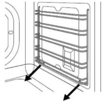
- Identify the two hooks at the bottom of the guide assembly and pull them gently downwards.
- Pull the guide assembly away from the side of the oven and remove by pulling the upper hooks of the assembly upwards from the side of the oven.
- Remove the side guide assembly from the oven.
natural_image
Technical line drawing of a multi-tiered storage unit with directional arrows indicating flow or movement (no text or symbols)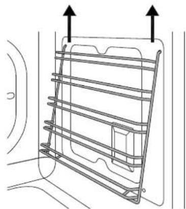
natural_image
Technical line drawing of a metal rack structure with two upward arrows indicating top and bottom directions (no text or symbols)REPLACING THE OVEN LIGHT
Warning!
Isolate the oven's power supply before changing the light bulb. DO NOT touch the bulb with your bare hands.
Oven side light (where fitted)
Bulb type: G9 halogen, 220 V, 40 W
- Ensure that the oven is off and cool.
- If necessary, remove the side guides from the oven.
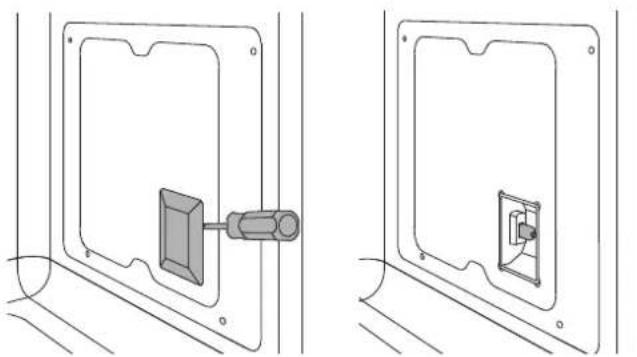
- Slide the tip of a fl at-head screwdriver between the glass cover and the bulb housing, taking care not to damage the seal.
• Gently turn the tip of the screwdriver to loosen the glass while keeping it in position with your fingers to prevent it falling and breaking. - Remove the glass and take out the old halogen bulb.
- Insert a new halogen bulb in the holder. DO NOT touch the bulb with your bare hands.

natural_image
Technical line drawing of two mechanical components mounted on a panel (no text or symbols)- Press the glass cover back on, repositioning the gasket.
- Reposition the oven rack.
- Refi t the side guide.
- Reinstate the power supply.
REPLACING RESERVOIR SEAL
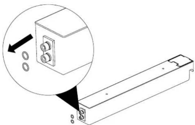
Each time the reservoir is removed, check that the seals are intact and correctly positioned. Replace them with those supplied if they should be damaged.
natural_image
Technical line drawing of a mechanical component with a magnified inset showing a close-up view of a housing (no text or symbols)CLEANING THE INTERNAL DOOR GLASS
The internal door glass can be easily removed for cleaning. It is not necessary to remove the door in order to clean the glass.

The glass can be cleaned in place, or removed for cleaning.
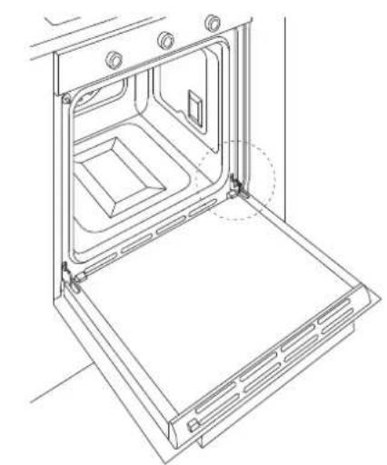
• Fully open the oven door.
- Fully open the blocking levers for both hinges.
- Slowly close the door until it blocks, checking that the levers have blocked the door.
- Remove the top cover of the door by pressing the round buttons on the left and right.
- Lift the top cover and remove.
Paying close attention to the sides of the glass:
- Slide the panes of glass out.
- Clean the glass.
- Repeat the operations above in reverse to reassemble the door.
N.B.: the markings on the glass must face outwards
If the hinges are not correctly blocked and the internal glass is removed, the door can close by itself.
natural_image
Line drawing of an oven with internal compartments and ventilation grilles (no text or symbols)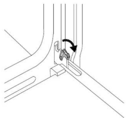
natural_image
Pure technical line drawing of a mechanical assembly with no text or symbols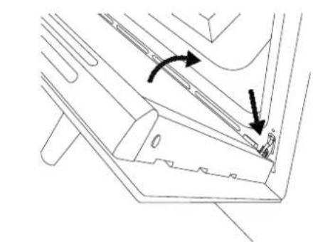
natural_image
Technical line drawing of a mechanical component with two directional arrows indicating motion (no text or symbols)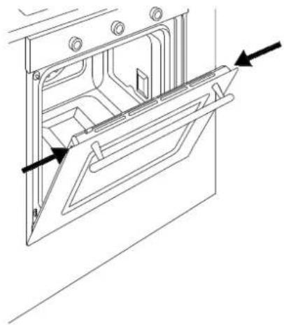
natural_image
Technical line drawing of a door frame with arrows indicating direction (no text or symbols)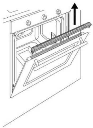
natural_image
Technical line drawing of a mechanical assembly with an upward arrow indicating motion (no text or symbols present)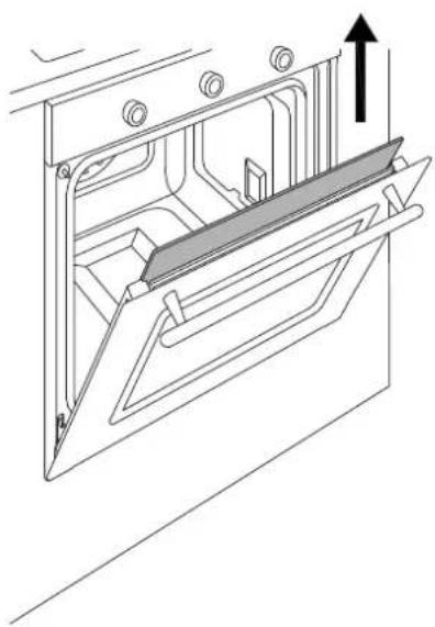
natural_image
Technical line drawing of a mechanical assembly with an upward arrow indicating motion (no text or symbols present)TROUBLESHOOTING
The oven is not working.
Is the oven power supply active? Check the circuit breaker, switch or fuse. Disconnect the oven from the power supply for around one minute by unplugging it or turning it off at the circuit breaker.
The oven does not heat up.
Check that showroom mode is not enabled.
Check that a time function is not active. Disconnect the oven from the power supply for around one minute by unplugging it or turning it off at the circuit breaker.
The knob will not stay in place.
The knob clip is broken: call customer service for a replacement.
The controls are very hot.
This is normal if the door is left open for a prolonged period of time with the oven running.
Check that the door closes correctly and that the cooking system is operational.
Food is overcooked.
When using a fan-assisted function, remember to lower the cooking temperature by 20^ C.
Food is undercooked.
When cooking large quantities of food, the cooking time must be increased proportionally.
Check that there is sufficient space around the oven dish to allow heat to circulate correctly.
Check that the door closes correctly.
Have a technician check the actual mains voltage.
Condensation forms on the oven door glass.
When cooking foods with a high water content, or during steam cooking, it is normal for condensation to form on the inside of the oven door and on the control panel.
Smoke forms during cooking.
It is normal for smoke to form inside the oven when cooking particularly fatty foods. When cooking with the grill, a certain quantity of smoke is normal.
The cleaning procedure is interrupted before it finishes.
A power failure has occurred.
Check that the ventilation openings in the carcase are correctly sized and located and are not blocked.
WARRANTY
Cleaning results are not satisfactory.
Check that all accessories and side racks have been removed.
Larger accumulations and residue should be removed manually before running the pyrolysis cycle.

The oven indicates that it is out of water.
Add water to the reservoir.
Check that the reservoir is correctly inserted.
Water coming out of the tray.
Check that the reservoir lid is correctly installed.
Check that the reservoir is not too full.
The water reservoir is difficult to clean.
The lid and the leak prevention device have not been removed.
Refer to the chapter "Cleaning the Water Reservoir".
The descaling procedure is interrupted before it finishes.
A power failure has occurred.
The function has been stopped by the user.
Carry out the procedure again.
There is dirty water on the base of the oven after the descaling procedure.
Remove the residual water and the descaling product from the base of the oven. Clean the oven cavity thoroughly.
WARRANTY AND CUSTOMER SERVICE: WWW.BERTAZZONI.COM

HANDLEIDING VOOR INSTALLATIE EN GEBRUIK INBOUW STOOMOVENS


3100532
INHOUDSOPGAVE
WAARSCHUWINGEN 4
VERANTWOORDELIJKHEID VAN DE FABRIKANT 4
MILIEUBESCHERMING 4
PLASTIC VERPAKKINGEN 4
IDENTIFICATIEPLAATJE 4
ALGEMENE WAARSCHUWINGEN OMTRENT DE VEILIGHEID 5
WAARSCHUWINGEN VOOR HET GEBRUIK 6
WAARSCHUWINGEN OVER HET TOESTEL 6
ACCESSOIRES/OPTIES 23
TELESCOPISCHE GELEIDERS 23
REINIGING VAN HET TOESTEL 24
EENVOUDIGE ONDERHOUDSWERKZAAMHEDEN 25
VERWIJDEREN VAN DE LATERALE GELEIDERS 25
VERVANGING VAN DE LAMP IN DE OVEN 25
VERVANGING PAKKINGEN RESERVOIR 25
REINIGING VAN DE GLAZEN BINNENKANT VAN DE OVENDEUR 26
STORINGEN 27
GARANTIE 27

VANAF DE SCHRIJFTAFEL VAN DE PRESIDENT
Beste klant,
Paolo Bertazzoni President
WAARSCHUWINGEN
LEES DE HANDLEIDING ALVORENS HET TOESTEL TE INSTALLEREN EN TE GEBRUIKEN.

natural_image
Simple line drawing of a rectangular frame with two vertical arrows labeled 't' pointing downward (no text or symbols beyond the arrow)
natural_image
Technical line drawing of a screwdriver inserted into a mechanical component (no text or symbols)
natural_image
Technical line drawing of a mechanical assembly with layered components and mounting holes (no text or symbols)natural_image
Simple diagram with three circles and a rectangle inside a rectangle, no text or symbols present.1
2
3
natural_image
Simple geometric shape: a rectangle inside a rectangle (no text or symbols)1
natural_image
Technical line drawing of a door with internal compartments and numbered parts (1-5), no text or symbols present.KOELING
natural_image
Diagram of a refrigerator interior showing door, drawer, and drawer with rotation arrows indicating movement (no text or symbols)natural_image
Technical illustration of a mechanical housing assembly with internal compartments and mounting holes (no text or symbols)natural_image
Technical line drawing of a mechanical component with an arrow indicating rotation (no text or symbols)TABEL MET INDICATIEVE BEREIDINGSTIJDEN
natural_image
Technical diagram of a door frame with a horizontal shelf and two black arrows indicating movement or assembly (no text or symbols present)natural_image
Technical diagram of a mechanical assembly with directional arrows indicating movement or force (no text or symbols present)
natural_image
Technical line drawing of a door frame with horizontal shelves and directional arrows indicating movement (no text or symbols)REINIGING VAN HET TOESTEL
natural_image
Technical line drawing of a multi-panel rack or vent system with directional arrows indicating flow or movement (no text or symbols)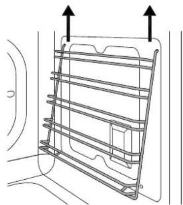
natural_image
Technical line drawing of a metal rack structure with two upward arrows indicating top and bottom directions (no text or symbols)VERVANGING VAN DE LAMP IN DE OVEN
Opgelet!
natural_image
Technical line drawing of a mechanical component with a rectangular block and attached rod (no text or symbols)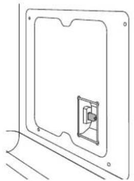
natural_image
Technical line drawing of a door frame with a small internal component, no text or symbols present
natural_image
Technical line drawing of a mechanical component with a magnified inset showing internal components (no text or symbols)REINIGING VAN DE GLAZEN BINNENKANT VAN DE OVENDEUR
natural_image
Technical line drawing of a door frame assembly and a mechanical bracket with a rotating knob (no text or symbols)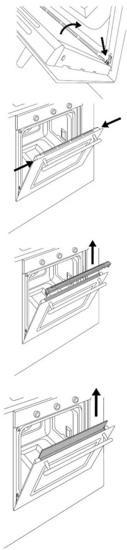

STORINGEN
De oven werkt niet
INNEHÅLLSFÖRTECKNING
WARNINGAR 4
TILLVERKARENS ANSVAR 4
MILJÖSKYDD 4
PLASTFÖRPACKNINGAR 4
TYPSKYLT 4
ALLMÄNNA SÄKERHETSVARNINGAR 5
VARNINGAR VID ANVÄNDNING 6
VARNINGAR FÖR APPARATEN 6
TEKNISK HANDBOK FÖR INSTALLATÖREN 7
INSÄTTANDE AV UGNEN 7
VIKTIGA VARNINGAR 7
INSTALLATION UNDER SPISHÄLL 8
INSTALLATION I INBYGGNADSSKÅP 8
FASTSÄTTNING AV UGNEN 9
ELANSLUTNING 9
UNDERHÄLL 10
BYTE AV KOMPONENTER 10
ANVÄNDNING 11
KONTROLLPANEL 11
MANÖVERORGAN UGN 2 MANÖVERRATTAR 11
MANÖVERORGAN UGN FULL TOUCH 11
UGNENS FUNKTIONER 11
FÖRSTA PÅSLAGNINGEN 12
FÖRE FÖRSTA ANVÄNDNINGEN 12
PLACERING AV GALLER 12
NEDKYLNING 12
FÖRVÄRMNING 12
UGNSLAMPA 12
VATTENHÄRDHET 12
ANVÄNDNING AV UGN 2 MANÖVERRATTAR 13
ANVÄNDNING AV FRONT TOUCH 13
TILLAGNINGSSÄTT 13
ÅNGA 16
KONDENS 17
RÅD FÖR TILLAGNING 17
ENERGIBESPARING 17
VATTENBEHÅLLARE 17
DROPPSKYDD 18
UNGEFÄRLIG TABELL FÖR TILLAGNING 19
ANVÄNDNING AV PEKSKÄRMEN 20
HANTERING AV TIDSFUNKTIONER 21
KÖKSTERMOMETER 21
ASSISTENT 22
TILLBEHÖR /TILLVAL 23
UTDRAGBARA SKENOR 23
RENGÖRING AV APPARATEN 24
ENKELT UNDERHÅLL 25
BORTTAGNING AV SIDOSKENORNA 25
BYTE AV UGNSLAMPA 25
BYTE AV BEHÅLLARENS TÄTNINGAR 25
RENGÖRING AV UGNSLUCKANS INVÄNDIGA GLAS 26
FUNKTIONSFEL 27
GARANTI 27
FRÅN DEN VERKSTÄLLANDE DIREKTÖRENS SKRIVBORD
Kära kund,
natural_image
Simple line drawing of a 3D rectangular box with two vertical arrows labeled 't' pointing downward (no text or symbols beyond the arrow)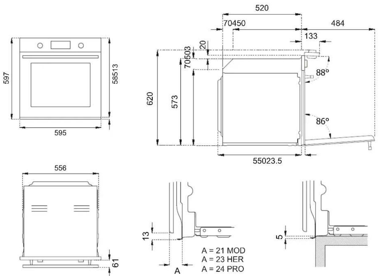

TEKNISK HANDBOK FÖR INSTALLATÖREN
INSTALLATION UNDER INBYGGNADSHÄLL
natural_image
Technical line drawing showing two views of a screwdriver inserted into a rack structure (no text or symbols)ELANSLUTNING
natural_image
Diagram of a cable with labeled components L and N, showing wires and a ground symbol (no text or symbols beyond labels)natural_image
Simple geometric shape: a rectangle inside a rectangle (no text or symbols)1
natural_image
Diagram of a kitchen appliance with open door, showing internal components and directional arrows (no text or symbols)natural_image
Technical illustration of a mechanical housing assembly with internal compartments and mounting holes (no text or symbols)natural_image
Technical line drawing of a mechanical component with an arrow indicating rotation (no text or symbols)UNGEFÄRLIG TABELL FÖR TILLAGNING
natural_image
Technical line drawing of a mechanical assembly with two arrows indicating assembly or movement (no text or symbols present)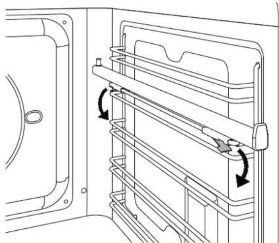
natural_image
Technical line drawing of a door frame with horizontal shelves and directional arrows indicating movement (no text or symbols)natural_image
Technical diagram of a door handle assembly with arrows indicating movement or force (no text or symbols present)
RENGÖRING AV APPARATEN
natural_image
Technical line drawing of a mechanical component with two directional arrows indicating movement or force (no text or symbols)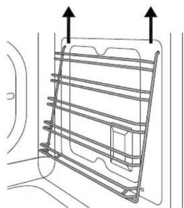
natural_image
Technical line drawing of a metal rack structure with two upward arrows indicating top and bottom directions (no text or symbols)BYTE AV UGNSLAMPA
Varning!
natural_image
Technical line drawing showing two views of a wall-mounted device with a central connector (no text or symbols)natural_image
Technical line drawing of a mechanical assembly with a magnified inset showing bolted components (no text or symbols)RENGÖRING AV UGNSLUCKANS INVÄNDIGA GLAS
natural_image
Technical line drawing showing a door frame and a mechanical component with a rotating knob (no text or symbols)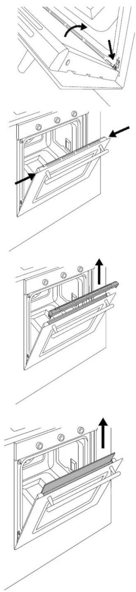
FUNKTIONSFEL
Ugnen fungerar inte.
INTRODUCTION DU FOUR 7
AVERTISSEMENTS IMPORTANTS 7
INSTALLATION SOUS PLAN DE CUISSON 8
INSTALLATION SUR COLONNE 8
FIXATION DU FOUR 9
BRANCHEMENT ÉLECTRIQUE 9
ENTRETIEN 10
REMPLACEMENT DES COMPOSANTS 10
UTILISATION 11
PANNEAU DE COMMANDE 11
COMMANDES DU FOUR À 2 BOUTONS 11
COMMANDES DU FOUR FULL TOUCH 11
FONCTIONS DU FOUR 11
PREMIER ALLUMAGE 12
AVANT LA PREMIÈRE UTILISATION 12
POSITIONNEMENT DES GRILLES 12
REFROIDISSEMENT 12
PRÉCHAUFFAGE 12
LUMIÈRE FOUR 12
DURETÉ DE L'EAU 12
natural_image
Simple line drawing of a 3D rectangular frame with two vertical arrows pointing downward, labeled '1' at the bottom (no text or symbols on the frame itself)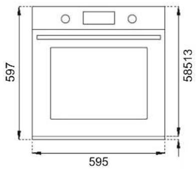

MANUEL TECHNIQUE POUR L'INSTALLATEUR
INSTALLATION SOUS PLAN DE CUISSON
natural_image
Technical line drawing of a screwdriver inserted into a mechanical component (no text or symbols)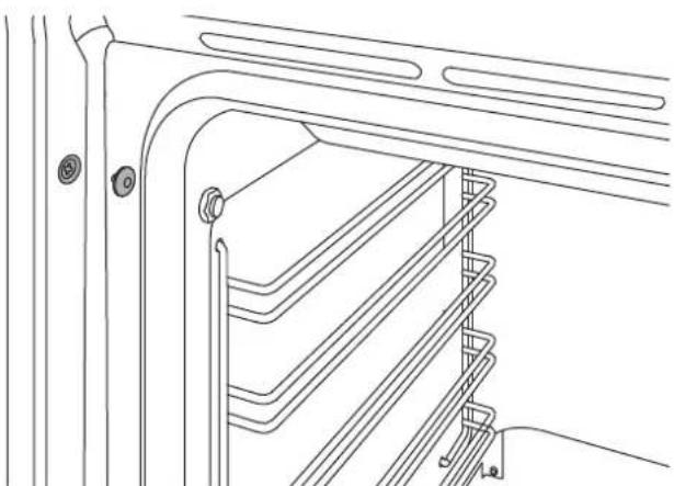
natural_image
Technical line drawing of a mechanical or architectural component with layered structure and mounting holes (no text or symbols)BRANCHEMENT ÉLECTRIQUE
natural_image
Diagram of a cable with labeled terminals L and N, showing a connector or connector inserted into a wire (no text or symbols beyond labels)REPLACEMENT DES COMPOSANTS
natural_image
Simple geometric shape: a rectangle inside a rectangle (no text or symbols)1
natural_image
Technical line drawing of a door with internal components and numbered labels (1–5), no readable text or symbols beyond labels.REFROIDISSEMENT
natural_image
Diagram of a refrigerator interior showing door, drawer, and drawer with rotation arrows indicating movement (no text or symbols)natural_image
Technical line drawing of a mechanical component with an arrow indicating rotation (no text or symbols)TABLEAU INDICATIF POUR LA CUISSON
natural_image
Technical line drawing of a door frame with a horizontal shelf and two black arrows indicating movement or assembly (no text or symbols)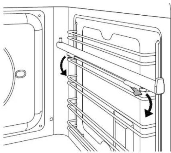
natural_image
Technical line drawing of a door frame with horizontal shelves and directional arrows indicating movement (no text or symbols)natural_image
Technical diagram of a mechanical assembly with directional arrows indicating movement or force (no text or symbols present)
NETTOYAGE DE L'APPAREIL
natural_image
Technical line drawing of a mechanical component with two directional arrows indicating movement or force (no text or symbols)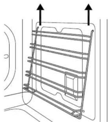
natural_image
Technical line drawing of a metal rack structure with two upward arrows indicating top and bottom directions (no text or symbols)REEMPLACEMENT DE L'AMPOULE DU FOUR
Attention!
natural_image
Technical line drawing of two electrical panel components with a fuse, one showing internal structure and the other showing a socket (no text or symbols)natural_image
Technical line drawing of a mechanical component with a magnified inset showing internal components (no text or symbols)NETTOYAGE DES VERRES INTÉRIEURS DE LA PORTE DU FOUR
natural_image
Technical line drawing of a mechanical assembly with a component and a close-up view showing a curved bracket (no text or symbols)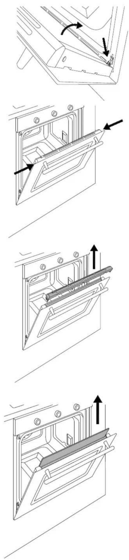
natural_image
Technical line drawings of a mechanical assembly with multiple views and directional arrows indicating motion (no text or symbols present)
DYSFONCTIONNEMENTS
- INDICE
- MANUALE TECNICO PER L'INSTALLATORE
- TABELLA INDICATIVA PER LA COTTURA
- PULIZIA DELL'APPARECCHIO
- PULIZIA VETRI INTERNI PORTA FORNO
- MALFUNZIONAMENTO
- INSTALLATION AND USER MANUAL BUILT-IN STEAM OVENS
- CONTENTS
- FROM THE DESK OF OUR PRESIDENT
- INTRODUCTION
- MANUFACTURER LIABILITY
- ENVIRONMENTAL PROTECTION
- PLASTIC PACKAGING
- APPLIANCE DATA PLATE
- GENERAL SAFETY INSTRUCTIONS
- INSTRUCTIONS FOR USE
- APPLIANCE WARNINGS
- TECHNICAL INSTALLATION INSTRUCTIONS
- INSTALLING THE OVEN IN THE UNIT
- IMPORTANT INFORMATION
- INSTALLATION UNDERNEATH A BUILT-IN HOB
- INSTALLING THE OVEN IN A TALL APPLIANCE HOUSING
- OVEN FASTENING
- ELECTRICAL CONNECTION
- MAINTENANCE
- REPLACING COMPONENTS
- CONTROL PANEL
- TWO-KNOB OVEN CONTROLS
- FULL-TOUCH OVEN CONTROLS
- OVEN FUNCTIONS
- USE
- FIRST USE
- BEFORE FIRST USE
- RACK POSITIONING
- COOLING
- PRE-HEATING
- OVEN LIGHT
- WATER HARDNESS
- USING TWO-KNOB OVENS
- COOKING MODES
- Warning: all cooking operations must take place with the door closed.
- Convection
- Fan
- Static
- Fast Preheat
- Turbo
- Bottom Bake
- Grill
- Fan with grill
- Assistant
- Specials
- Dehydrate
- Defrost
- Warming
- Proofing
- Sabbath
- Eco
- Settings
- Cleaning (only eleven-function pyrolytic oven)
- Pyro
- Remove the silicone cap from the temperature probe socket and insert the metal cap.
- Eco Pyro
- Hydroclean
- Hydroclean (eleven-function oven only)
- STEAM
- Steam Levels
- Pump
- Water Reservoir
- Steam Accessories
- Derivative Function
- Regeneration
- CONDENSATION
- COOKING TIPS
- SAVING ENERGY
- DRIP TRAY
- SCOOKING GUIDELINE
- USING THE TOUCHSCREEN DISPLAY
- SETTINGS MENU
- Brightness
- Audio
- Language
- Clock
- Showroom Mode
- Weight Unit
- Temp Unit
- ECO Mode
- MANAGING THE TIME FUNCTIONS
- Timer △
- Cooking Time
- Start at Ⓤ
- TEMPERATURE PROBE (where available)
- ACCESSORIES / OPTIONAL EXTRASACCESSORIES / OPTIONAL EXTRA
- TELESCOPIC RAILS
- Removing the Telescopic Rails
- CLEANING THE APPLIANCE
- Cleaning enamelled or painted parts:
- Cleaning Stainless-Steel Parts:
- Cleaning the Door Glazing:
- Cleaning the Oven Racks:
- Cleaning Handles:
- Seal:
- Descaling
- BASIC MAINTENANCE
- REMOVING THE SIDE GUIDES
- REPLACING THE OVEN LIGHT
- Warning!
- Oven side light (where fitted)
- REPLACING RESERVOIR SEAL
- CLEANING THE INTERNAL DOOR GLASS
- TROUBLESHOOTING
- The oven is not working.
- The oven does not heat up.
- The knob will not stay in place.
- The controls are very hot.
- Food is overcooked.
- Food is undercooked.
- Condensation forms on the oven door glass.
- Smoke forms during cooking.
- The cleaning procedure is interrupted before it finishes.
- WARRANTY
- Cleaning results are not satisfactory.
- The oven indicates that it is out of water.
- Water coming out of the tray.
- The water reservoir is difficult to clean.
- The descaling procedure is interrupted before it finishes.
- There is dirty water on the base of the oven after the descaling procedure.
- WARRANTY AND CUSTOMER SERVICE: WWW.BERTAZZONI.COM
- HANDLEIDING VOOR INSTALLATIE EN GEBRUIK INBOUW STOOMOVENS
- INHOUDSOPGAVE
- VANAF DE SCHRIJFTAFEL VAN DE PRESIDENT
- WAARSCHUWINGEN
- KOELING
- TABEL MET INDICATIEVE BEREIDINGSTIJDEN
- REINIGING VAN HET TOESTEL
- VERVANGING VAN DE LAMP IN DE OVEN
- Opgelet!
- REINIGING VAN DE GLAZEN BINNENKANT VAN DE OVENDEUR
- STORINGEN
- De oven werkt niet
- INNEHÅLLSFÖRTECKNING
- FRÅN DEN VERKSTÄLLANDE DIREKTÖRENS SKRIVBORD
- TEKNISK HANDBOK FÖR INSTALLATÖREN
- INSTALLATION UNDER INBYGGNADSHÄLL
- ELANSLUTNING
- UNGEFÄRLIG TABELL FÖR TILLAGNING
- RENGÖRING AV APPARATEN
- BYTE AV UGNSLAMPA
- Varning!
- RENGÖRING AV UGNSLUCKANS INVÄNDIGA GLAS
- FUNKTIONSFEL
- Ugnen fungerar inte.
- MANUEL TECHNIQUE POUR L'INSTALLATEUR
- INSTALLATION SOUS PLAN DE CUISSON
- BRANCHEMENT ÉLECTRIQUE
- REPLACEMENT DES COMPOSANTS
- REFROIDISSEMENT
- TABLEAU INDICATIF POUR LA CUISSON
- NETTOYAGE DE L'APPAREIL
- REEMPLACEMENT DE L'AMPOULE DU FOUR
- Attention!
- NETTOYAGE DES VERRES INTÉRIEURS DE LA PORTE DU FOUR
- DYSFONCTIONNEMENTS
Brand : BERTAZZONI
Model : F6011MODVLXC
Category : Oven