
50-723 T2 - Industrial vacuum cleaner DELTA - Free user manual and instructions
Find the device manual for free 50-723 T2 DELTA in PDF.

| Product Type | Industrial Vacuum / Dust Collector |
| Brand | Delta |
| Model | 50-723 T2 |
| Motor Power | 1 HP (0.75 kW) |
| Voltage / Frequency | 120 V ~ 60 Hz |
| Rated Current | 12-16 A (depending on configuration) |
| Inlet Diameter | 10.16 cm (4 inches) |
| Filtration Fineness | Filter bag: 2 microns; Collection bag: 152.4 microns (6 mils) |
| Number of Bags | 2: one filter bag and one plastic collection bag |
| Suction Materials | Dry non-explosive dust (wood, etc.) - no metal dust, liquids, or burning substances |
| Safety | Mandatory grounding; lockable switch; ANSI approved protections |
| Mounting | On casters (2 wheels + 2 swivel casters); carrying handle |
| Provided Accessories | Y-inlet adapter, bag retaining ring, caps |
| Maintenance | Regular filter cleaning; bag inspection; compressed air for ducts |
| Spare Parts | Delta original parts recommended; customer service: 1-800-223-7278 or www.DeltaMachinery.com |
| Repairability | Delta authorized service centers; repairs guaranteed for material and workmanship defects |
| Warranty | 5 years limited for new products; 180 days for refurbished |
| Recommended Use | Woodworking workshop with compatible machines (4-inch hose) |
| Electrical Compatibility | 3-wire extension cord with grounding; minimum 12 AWG for separate 20 A circuit |
Frequently Asked Questions - 50-723 T2 DELTA
User questions about 50-723 T2 DELTA
0 question about this device. Answer the ones you know or ask your own.
Ask a new question about this device
Download the instructions for your Industrial vacuum cleaner in PDF format for free! Find your manual 50-723 T2 - DELTA and take your electronic device back in hand. On this page are published all the documents necessary for the use of your device. 50-723 T2 by DELTA.
USER MANUAL 50-723 T2 DELTA
natural_image
Line drawing of a DELTA industrial machine with wheels and a cylindrical tank (no text or symbols on the device itself)50-723 T2

TABLE OF CONTENTS
IMPORTANT SAFETY INSTRUCTIONS ....2
SAFETY GUIDELINES - DEFINITIONS ....2
GENERAL SAFETY RULES ....3
ADDITIONAL SPECIFIC SAFETY RULES ....4
FUNCTIONAL DESCRIPTION ......6
CARTON CONTENTS 7
ASSEMBLY 8
OPERATION ....17
TROUBLESHOOTING ....17
MAINTENANCE ....18
SERVICE....18
ACCESSORIES ....19
FRANCAIS ......21
ESPAÑOL....41
IMPORTANT SAFETY INSTRUCTIONS
⚠ WARNING: Read and understand all warnings and operation instructions before using any tool or equipment. Always follow basic safety precautions to reduce the risk of personal injury. Improper operation, maintenance or modification of tools or equipment could result in serious injury and property damage. There are certain applications for which tools and equipment are designed. This product should NOT be modified and/or used for any application other than for which it was designed.
If you have any questions relative to its application DO NOT use the product until you have written DELTA® Power Equipment Corporation and we have advised you. Contact us online at www.DeltaMachinery.com or by mail at Technical Service Manager, DELTA® Power Equipment Corporation, 2651 New Cut Road, Spartanburg, SC 29303. Information regarding the safe and proper operation of this tool is available from the following sources:
• Power Tool Institute, 1300 Sumner Avenue, Cleveland, OH 44115-2851 or online at www.powertoolinstitute.com
• National Safety Council, 1121 Spring Lake Drive, Itasca, IL 60143-3201
- American National Standards Institute, 25 West 43rd Street, 4 floor, New York, NY 10036 www.ansi.org - ANSI 01.1 Safety Requirements for Woodworking Machines
• U.S. Department of Labor regulations www.osha.gov
SAVE THESE INSTRUCTIONS!
SAFETY GUIDELINES - DEFINITIONS
It is important for you to read and understand this manual. The information it contains relates to protecting YOUR SAFETY and PREVENTING PROBLEMS. The symbols below are used to help you recognize this information.
▲DANGER: indicates an imminently hazardous situation which, if not avoided, will result in death or serious injury.
⚠ WARNING: indicates a potentially hazardous situation which, if not avoided, could result in death or serious injury.
CAUTION: indicates a potentially haz ard ous situation which, if not avoided, may result in minor or moderate injury.
▲CAUTION: used without the safety alert symbol indicates potentially hazardous situation which, if not avoided, may result in property damage.
WARNING:
Some dust created by power sanding, sawing, grinding, drilling, and other construction activities contains chemicals known to the state of california to cause cancer, birth defects or other reproductive harm. Some examples of these chemicals are:
- Lead from lead-based paints,
- Crystalline silica from bricks and cement and other masonry products, and
- Arsenic and chromium from chemically-treated lumber (CCA).
Your risk from these exposures varies, depending on how often you do this type of work. To reduce your exposure to these chemicals: work in a well-ventilated area, and work with approved safety equipment, such as those dust masks that are specially designed to filter out microscopic particles.
GENERAL SAFETY RULES
⚠ WARNING: Failure to follow these rules may result in serious personal injury.
-
FOR YOUR OWN SAFETY, READ THE INSTRUCTION MANUAL BEFORE OPERATING THE MACHINE. Learning the machine's application, limitations, and specific hazards will greatly minimize the possibility of accidents and injury.
-
WEAR EYE AND HEARING PROTECTION. ALWAYS USE SAFETY GLASSES. Everyday eyeglasses are NOT safety glasses. USE CERTIFIED SAFETY EQUIPMENT. Eye protection equipment should comply with ANSI Z87.1 standards. Hearing equipment should comply with ANSI S3.19 standards.
-
WEAR PROPER APPAREL. Do not wear loose clothing, gloves, neckties, rings, bracelets, or other jewelry which may get caught in moving parts. Nonslip protective footwear is recommended. Wear protective hair covering to contain long hair.
-
DO NOT USE THE MACHINE IN A DANGEROUS ENVIRONMENT. The use of power tools in damp or wet locations or in rain can cause shock or electrocution. Keep your work area well-lit to prevent tripping or placing arms, hands, and fingers in danger.
-
MAINTAIN ALL TOOLS AND MACHINES IN PEAK CONDITION. Keep tools sharp and clean for best and safest performance. Follow instructions for lubricating and changing accessories. Poorly maintained tools and machines can further damage the tool or machine and/or cause injury.
-
CHECK FOR DAMAGED PARTS. Before using the machine, check for any damaged parts. Check for alignment of moving parts, binding of moving parts, breakage of parts, and any other conditions that may affect its operation. A guard or any other part that is damaged should be properly repaired or replaced with DELTA® or factory authorized replacement parts. Damaged parts can cause further damage to the machine and/or injury.
-
KEEP THE WORK AREA CLEAN. Cluttered areas and benches invite accidents.
-
KEEP CHILDREN AND VISITORS AWAY. Your shop is a potentially dangerous environment. Children and visitors can be injured.
-
REDUCE THE RISK OF UNINTENTIONAL STARTING. Make sure that the switch is in the "OFF" position before plugging in the power cord. In the event of a power failure, move the switch to the "OFF" position. An accidental start-up can cause injury. Do not touch the plug's metal prongs when unplugging or plugging in the cord.
-
USE THE GUARDS. Check to see that all guards are in place, secured, and working correctly to prevent injury.
-
REMOVE ADJUSTING KEYS AND WRENCHES BEFORE STARTING THE MACHINE. Tools, scrap pieces, and other debris can be thrown at high speed, causing injury.
-
USE THE RIGHT MACHINE. Don't force a machine or an attachment to do a job for which it was not designed. Damage to the machine and/or injury may result.
-
USE RECOMMENDED ACCESSORIES. The use of accessories and attachments not recommended by DELTA® may cause damage to the machine or injury to the user.
-
USE THE PROPER EXTENSION CORD. Make sure your extension cord is in good condition. When using an extension cord, be sure to use one heavy enough to carry the current your product will draw. An undersized cord will cause a drop in line voltage, resulting in loss of power and overheating. See the Extension Cord Chart for the correct size depending on the cord length and nameplate ampere rating. If in doubt, use the next heavier gauge. The smaller the gauge number, the heavier the cord.
-
SECURE THE WORKPIECE. Use clamps or a vise to hold the workpiece when practical. Loss of control of a workpiece can cause injury.
-
FEED THE WORKPIECE AGAINST THE DIRECTION OF THE ROTATION OF THE BLADE, CUTTER, OR ABRASIVE SURFACE. Feeding it from the other direction will cause the workpiece to be thrown out at high speed.
-
DON'T FORCE THE WORKPIECE ON THE MACHINE. Damage to the machine and/or injury may result.
-
DON'T OVERREACH. Loss of balance can make you fall into a working machine, causing injury.
-
NEVER STAND ON THE MACHINE. Injury could occur if the tool tips, or if you accidentally contact the cutting tool.
-
NEVER LEAVE THE MACHINE RUNNING UNATTENDED. TURN THE POWER OFF. Don't leave the machine until it comes to a complete stop. A child or visitor could be injured.
-
TURN THE MACHINE "OFF", AND DISCONNECT THE MACHINE FROM THE POWER SOURCE before installing or removing accessories, changing cutters, adjusting or changing set-ups. When making repairs, be sure to lock the start switch in the "OFF" position. An accidental start-up can cause injury.
-
MAKE YOUR WORKSHOP CHILDPROOF WITH PADLOCKS, MASTER SWITCHES, OR BY REMOVING STARTER KEYS. The accidental start-up of a machine by a child or visitor could cause injury.
-
STAY ALERT, WATCH WHAT YOU ARE DOING, AND USE COMMON SENSE. DO NOT USE THE MACHINE WHEN YOU ARE TIRED OR UNDER THE INFLUENCE OF DRUGS, ALCOHOL, OR MEDICATION. A moment of inattention while operating power tools may result in injury.
-
A/SPIN3 IS TOOL CAN GENERATE AND DISBURSE DUST OR OTHER AIRBORNE PARTICLES, INCLUDING WOOD DUST, CRYSTALLINE SILICA DUST AND ASBESTOS DUST. Direct particles away from face and body. Always operate tool in well ventilated area and provide for proper dust removal. Use dust collection system wherever possible. Exposure to the dust may cause serious and permanent respiratory or other injury, including silicosis (a serious lung disease), cancer, and death. Avoid breathing the dust, and avoid prolonged contact with dust. Allowing dust to get into your mouth or eyes, or lay on your skin may promote absorption of harmful material. Always use properly fitting NIOSH/OSHA approved respiratory protection appropriate for the dust exposure, and wash exposed areas with soap and water.
ADDITIONAL SPECIFIC SAFETY RULES
WARNING:
Failure to follow these rules may result in serious personal injury.
⚠ WARNING: DO NOT USE THIS UNIT TO FILTER
METAL DUST. Combining wood and metal dust can create an explosion or fire hazard. This unit is intended to filter non-explosive atmospheres only.
WARNING: DO NOT USE THIS UNIT TO
DISSIPATE FUMES OR SMOKE. Explosions or fire can result. This dust collector is intended for use where only dry airborne dust is present. Its use should be limited to non-explosive, non-metallic atmospheres.
- DO NOT OPERATE THIS UNIT UNTIL IT IS COMPLETELY ASSEMBLED AND INSTALLED ACCORDING TO THE INSTRUCTIONS. A unit incorrectly assembled can cause injury.
- OBTAIN ADVICE FROM YOUR SUPERVISOR, IN-STRUCTOR, OR ANOTHER QUALIFIED PERSON if you are not thoroughly familiar with the operation of this unit. Knowledge is safety.
- FOLLOW ALL WIRING CODES and recommended electrical connections to prevent electrical shock or electrocution.
- DO NOT PULL THIS UNIT BY THE POWER CORD. Do not allow the power cord to come in contact with sharp instruments or edges, hot surfaces, or oil or grease. Do not place any weight on top of the power cord. A damaged power cord can cause electrical shock or electrocution.
- SUPPORT THIS UNIT OR SECURELY CLAMP IT TO THE WORK SURFACE WHEN IT IS USED IN A PORTABLE APPLICATION to eliminate potential injury and/or damage from falling.
- ENSURE THAT THE INTAKE AND EXHAUST AREAS ARE CLEAR PRIOR TO STARTING THE UNIT. Clogged intakes or exhausts can cause an explosion and/or fire.
- DO NOT USE THE DUST COLLECTOR to pick up flammable liquids such as gasoline. Do not use the dust collector near flammable or combustible liquids. Explosion and/or fire can occur.
- KEEP ARMS, HANDS, AND FINGERS AWAY FROM THE FAN. Avoid all exposure to rotating parts to prevent injury.
-
DO NOT OPERATE THIS UNIT WITHOUT THE DUST COLLECTION BAG IN PLACE AND PROPERLY SECURED. Sawdust and other debris can provide the potential for fire and/or explosion and can also cause inhalation problems.
-
INSPECT THE DUST BAG FOR CUTS, RIPS, OR TEARS. Replace damaged bags or vacuum hoses. Sawdust and other debris can provide the potential for fire and/or explosion and can also cause inhalation problems.
- ALWAYS USE THE INTAKE CAPS TO COVER UNUSED DUST PORTS. Debris can cause damage to the unit and injury.
- DO NOT ATTEMPT TO REMOVE OR REPLACE the dust collection bag(s) while the unit is connected to the power source. Exposed fan blades can cause severe injuries.
- MAINTAIN THE UNIT IN TOP CONDITION. Clogged filters can increase the potential for fire or explosion. Follow all instructions for changing and cleaning filters.
- STORE THIS UNIT IN A LOCATION that eliminates the potential for damage to the power cord. A damaged power cord can cause shock or electrocution. Safely store power cord on the unit to eliminate tripping hazards.
- TURN THE UNIT "OFF" AND DISCONNECT THE UNIT from the power source before installing or removing accessories, before adjusting or changing set-ups, or when making repairs. An accidental start-up can cause serious injury.
- TURN THE UNIT "OFF", disconnect the unit from the power source, and clean the table/work area before leaving the area.
SAVE THESE INSTRUCTIONS.
Refer to them often and use them to instruct others.
POWER CONNECTIONS
A separate electrical circuit should be used for your machines. This circuit should not be less than #12 wire and should be protected with a 20 Amp time lag fuse. If an extension cord is used, use only 3-wire extension cords which have 3-prong grounding type plugs and matching receptacle which will accept the machine's plug. Before connecting the machine to the power line, make sure the switch (s) is in the "OFF" position and be sure that the electric current is of the same characteristics as indicated on the machine. All line connections should make good contact. Running on low voltage will damage the machine.
▲DANGER Do not expose the machine to rain or operate the machine in damp locations.
MOTOR SPECIFICATIONS
Your machine is wired for 120V, 60 HZ alternating current. Before connecting the machine to the power source, make sure the switch is in the "OFF" position.
GROUNDING INSTRUCTIONS
▲ DANGER This machine must be grounded while in use to protect the operator from electric shock.
1. All grounded, cord-connected machines:
In the event of a malfunction or breakdown, grounding provides a path of least resistance for electric current to reduce the risk of electric shock. This machine is equipped with an electric cord having an equipment-grounding conductor and a grounding plug. The plug must be plugged into a matching outlet that is properly installed and grounded in accordance with all local codes and ordinances.
Do not modify the plug provided - if it will not fit the outlet, have the proper outlet installed by a qualified electrician. Improper connection of the equipment-grounding conductor can result in risk of electric shock. The conductor with insulation having an outer surface that is green with or without yellow stripes is the equipment-grounding conductor. If repair or replacement of the electric cord or plug is necessary, do not connect the equipment-grounding conductor to a live terminal.
Check with a qualified electrician or service personnel if the grounding instructions are not completely understood, or if in doubt as to whether the machine is properly grounded.
Use only 3-wire extension cords that have 3-prong grounding type plugs and matching 3-conductor receptacles that accept the machine's plug, as shown in Fig. A. Repair or replace damaged or worn cord immediately.
2. Grounded, cord-connected machines intended for use on a supply circuit having a nominal rating less than 150 volts:
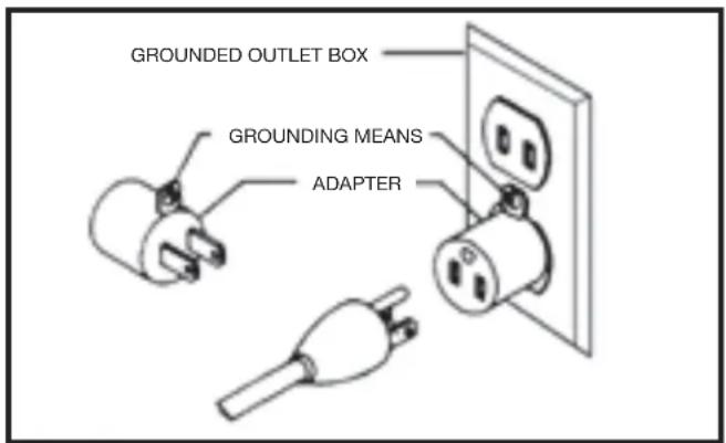
If the machine is intended for use on a circuit that has an outlet that looks like the one illustrated in Fig. A, the machine will have a grounding plug that looks like the plug illustrated in Fig. A. A temporary adapter, which looks like the adapter illustrated in Fig. B, may be used to connect this plug to a matching 2-conductor receptacle as shown in Fig. B if a properly grounded outlet is not available. The temporary adapter should be used only until a properly grounded outlet can be installed by a qualified electrician. The green-colored rigid ear, lug, and the like, extending from the adapter must be connected to a permanent ground such as a properly grounded outlet box. Whenever the adapter is used, it must be held in place with a metal screw.
NOTE: In Canada, the use of a temporary adapter is not permitted by the Canadian Electric Code.
▲ DANGER In all cases, make certain that the receptacle in question is properly grounded. If you are not sure, have a qualified electrician check the receptacle.
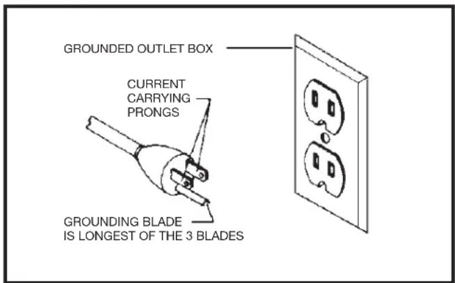
Fig. A Fig. B
The motor supplied with your machine is a dual voltage, 120/240 volt motor. It is shipped ready-to-run for 120 volt operation. However, it can be converted for 240 volt operation.
A qualified electrician should do the conversion, or the machine can be taken to an Authorized DELTA® Service Center. When completed, the machine must conform to the National Electric Code and all local codes and ordinances.
The machine is converted by re-wiring the motor for 240 volts, installing a 240 volt plug on the power supply cord and replacing the switch with one that is rated for 240 volt operation.
Be sure the 240 volt plug is only used in an outlet having the same configuration as the plug illustrated in Fig. C. No adapter should be used with the 240 volt plug.
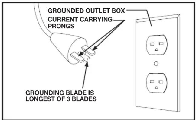
FIG. C
⚠ WARNING: In all cases, make certain that the receptacle in question is properly grounded. If you are not sure, have a qualified electrician check the receptacle.
EXTENSION CORDS
⚠ WARNING Use proper extension cords. Make sure your extension cord is in good condition and is a 3-wire extension cord which has a 3-prong grounding type plug and matching receptacle which will accept the machine's plug. When using an extension cord, be sure to use one heavy enough to carry the current of the machine. An undersized cord will cause a drop in line voltage, resulting in loss of power and overheating. Fig. D-1 or D-2, shows the correct gauge to use depending on the cord length. If in doubt, use the next heavier gauge. The smaller the gauge number, the heavier the cord.
| MINIMUM GAUGE EXTENSION CORDRECOMMENDED SIZES FOR USE WITH STATIONARY ELECTRIC MACHINES | |||
| Ampere Rating | Volts | Total Length of Cord in Feet | Gauge of Extension Cord |
| 0-6 | 120 | up to 25 | 18 AWG |
| 0-6 | 120 | 25-50 | 16 AWG |
| 0-6 | 120 | 50-100 | 16 AWG |
| 0-6 | 120 | 100-150 | 14 AWG |
| 6-10 | 120 | up to 25 | 18 AWG |
| 6-10 | 120 | 25-50 | 16 AWG |
| 6-10 | 120 | 50-100 | 14 AWG |
| 6-10 | 120 | 100-150 | 12 AWG |
| 10-12 | 120 | up to 25 | 16 AWG |
| 10-12 | 120 | 25-50 | 16 AWG |
| 10-12 | 120 | 50-100 | 14 AWG |
| 10-12 | 120 | 100-150 | 12 AWG |
| 12-16 | 120 | up to 25 | 14 AWG |
| 12-16 | 120 | 25-50 | 12 AWG |
| 12-16 | 120 | GREATER THAN 50 FEET NOT RECOMMENDED | |
| MINIMUM GAUGE EXTENSION CORDRECOMMENDED SIZES FOR USE WITH STATIONARY ELECTRIC MACHINES | |||
| Ampere Rating | Volts | Total Length of Cord in Feet | Gauge of Extension Cord |
| 0-6 | 240 | up to 50 | 18 AWG |
| 0-6 | 240 | 50-100 | 16 AWG |
| 0-6 | 240 | 100-200 | 16 AWG |
| 0-6 | 240 | 200-300 | 14 AWG |
| 6-10 | 240 | up to 50 | 18 AWG |
| 6-10 | 240 | 50-100 | 16 AWG |
| 6-10 | 240 | 100-200 | 14 AWG |
| 6-10 | 240 | 200-300 | 12 AWG |
| 10-12 | 240 | up to 50 | 16 AWG |
| 10-12 | 240 | 50-100 | 16 AWG |
| 10-12 | 240 | 100-200 | 14 AWG |
| 10-12 | 240 | 200-300 | 12 AWG |
| 12-16 | 240 | up to 50 | 14 AWG |
| 12-16 | 240 | 50-100 | 12 AWG |
| 12-16 | 240 | GREATER THAN 100 FEET NOT RECOMMENDED | |
Fig. D-1 Fig. D-2
FUNCTIONAL DESCRIPTION
FOREWORD
The DELTA® Industrial Model 50-723 T2 Dust Collector will connect to woodworking machines that accept a 4" diameter hose. The 50-723 T2 comes with one 2 micron filter bag and two 6 mil plastic collection bag.
NOTICE: The photo on the manual cover illustrates the current production model. All other illustrations contained in the manual are representative only and may not depict the actual labeling or accessories included. These are intended to illustrate technique only.
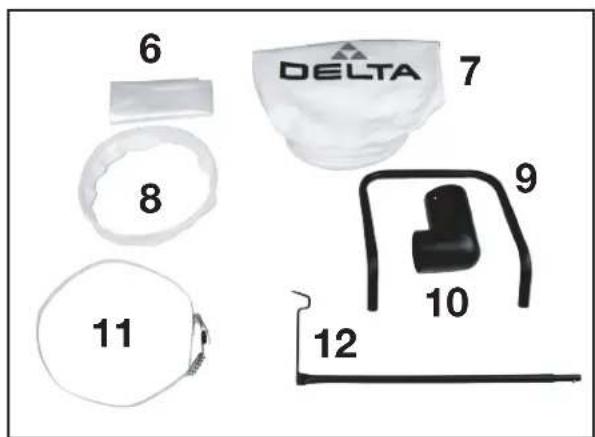
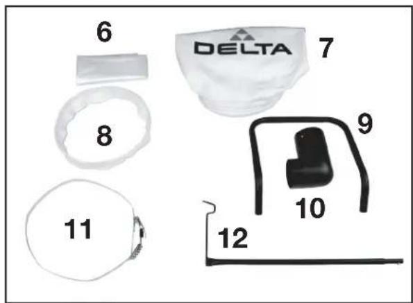
CARTON CONTENTS
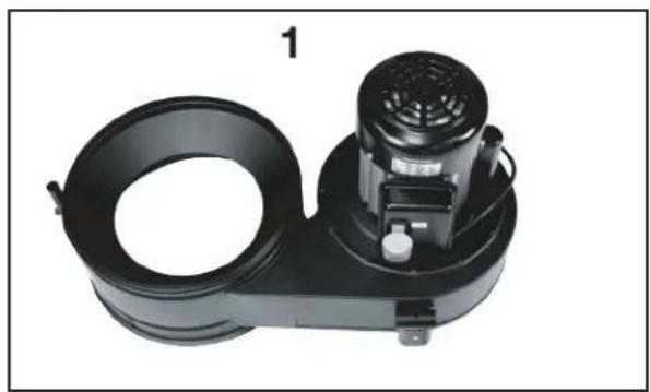
natural_image
Black industrial air purifier unit with cooling fan and housing (no visible text or symbols)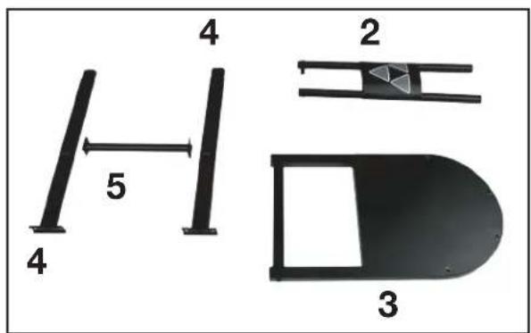
-
Blower Housing Assembly
-
Front Support Assembly
- Base Frame
- Rear Blower Housing Support (2)
-
Rear Stand Cross Support
-
Dust Collection PE Bag
-
Dust Filter Bag
- Retainer Strap
- Handle
- Inlet Adapter
- Dust Collection Bag Ring
-
Hanger Assembly
-
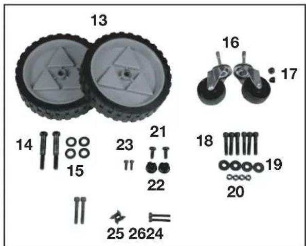
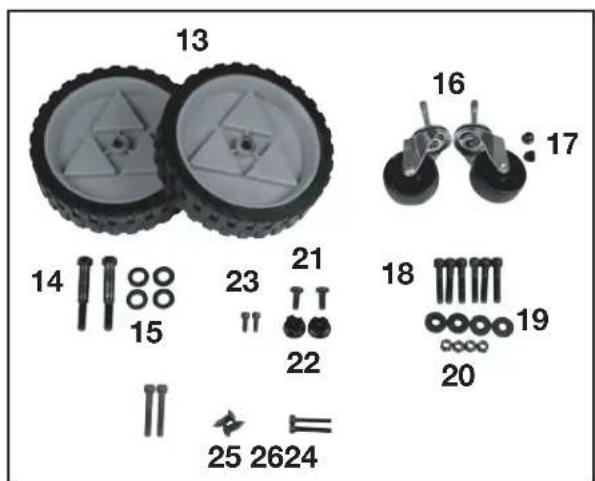
Rear Wheel (2)
- M10 Hex Head Shoulder Bolt (2)
- M12 Flat Washer
- Swivel Casters (2)
- Acorn Nuts (2)
- M8 x 45 Hex Socket Head Screw (6)
- M8 Flat Washer (4)
- M8 Lock Nut (4)
- Round Head Phillips Self-tapping screws (2)
- Tube End Cap (2)
- M6 x 10 Hex Socket Head Screw (2)
- M8 x 55 Hex Socket Head Screw (2)
- M5 Round Head Phillips Screw (2)
- M6 x 40 Hex Socket Head Screw (2)
ASSEMBLY
⚠ WARNING For your own safety, do not connect the machine to the power source until the machine is completely assembled and you read and understand the entire instruction manual.
ASSEMBLY TIME ESTIMATE
30 minutes to 1 hour
CAUTION This machine is heavy. Use two or more people when lifting.
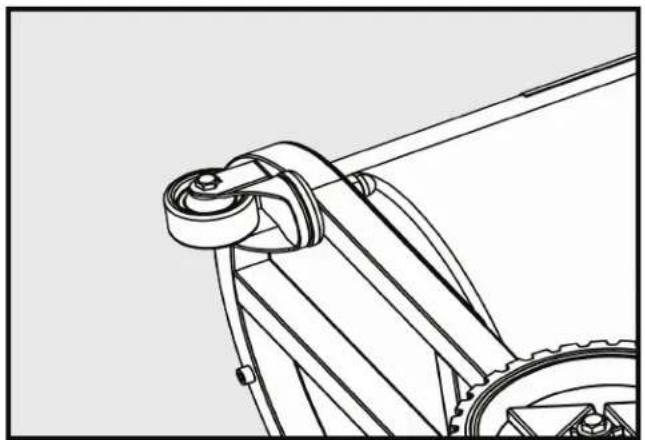
ATTACHING THE CASTERS
- Turn the base frame onto its side (Fig 1).
- Insert threaded portion of caster into through hole on the bottom of the base frame.
- Tighten acorn nut. (17)
- Repeat for the other caster.
natural_image
Technical line drawing of a mechanical assembly with gears and a lever (no text or symbols)FIGURE 1
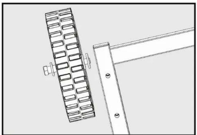
ATTACHING THE REAR WHEELS
- Place base frame upright.
- Insert M12 flat washer (15) onto shoulder bolt (14) (Fig 2).
- Insert shoulder bolt (14) through rear wheel (13).
- Place another M12 flat washer (15) between wheel and base.
- Tighten shoulder bolt. (14)
- Repeat for other wheel.
natural_image
Technical line drawing of a mechanical assembly with a grid-like component and a bracket (no text or symbols)FIGURE 2
ASSEMBLY (continued)
ATTACHING REAR BLOWER HOUSING SUPPORT
- Place base frame on side.
- Align Rear blower housing support with through holes.
- Insert M8 x 45mm hex socket head screw (18) through base support and base frame as shown.
- Place M8 flat washer (19) and M8 lock nut (20) on bottom side (Fig 3).
- Tighten lock nut.
- Repeat for other side.
natural_image
Technical line drawing of a mechanical frame assembly with two tires, no text or symbols presentFIGURE 3
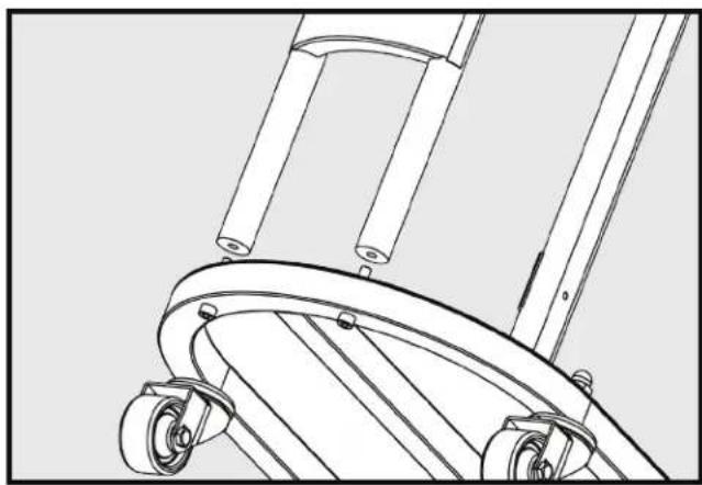
ATTACHING FRONT SUPPORT ASSEMBLY
- Place unit on its side.
- Align front support assembly with through holes at front of base frame.
- Insert M8 x 45mm hex socket head screw (18) through hole in base frame and thread into front support (Fig 4).
- Tighten screw.
- Repeat on other side.
natural_image
Technical line drawing of a mechanical device with wheels and legs (no text or symbols)FIGURE 4
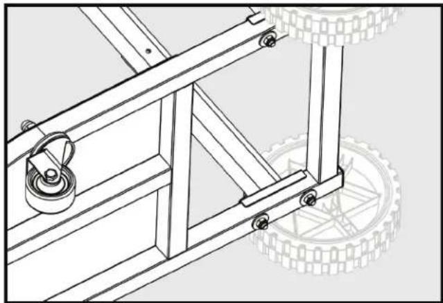
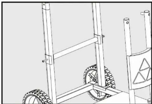
ATTACHING REAR STAND CROSS SUPPORT
- Place unit upright.
- Align rear stand cross support with through hole on rear blower housing support.
- Insert M6 hex socket head screw (26) through rear base support hole and thread into cross support (Fig 5).
- Tighten screw.
- Repeat on other side.
natural_image
Technical line drawing of a wheeled cart with tires and a warning sign (no text or symbols)FIGURE 5
ASSEMBLY (continued)
ATTACHING MOTOR BLOWER ASSEMBLY TO STAND
NOTE: TWO PEOPLE ARE NEEDED FOR THIS STEP
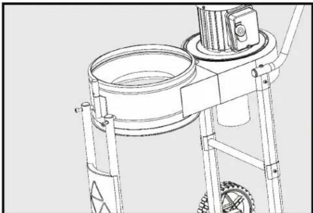
- Place motor blower assembly onto stand.
- Align the brackets on the blower housing, on the motor end, to the rear blower housing supports.
- Rear blower housing supports fit inside the brackets on the blower housing, as shown. (Fig 6)
natural_image
Technical line drawing of a mechanical assembly with no visible text or symbolsFIGURE 6
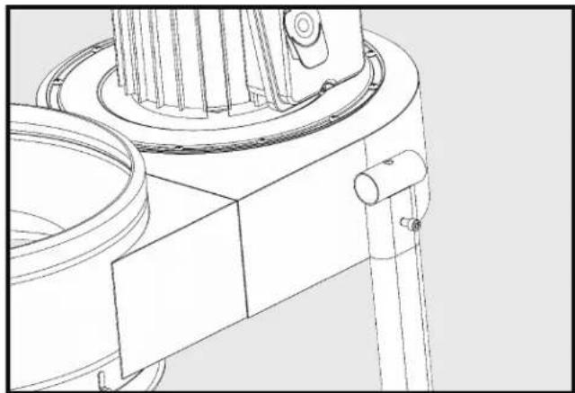
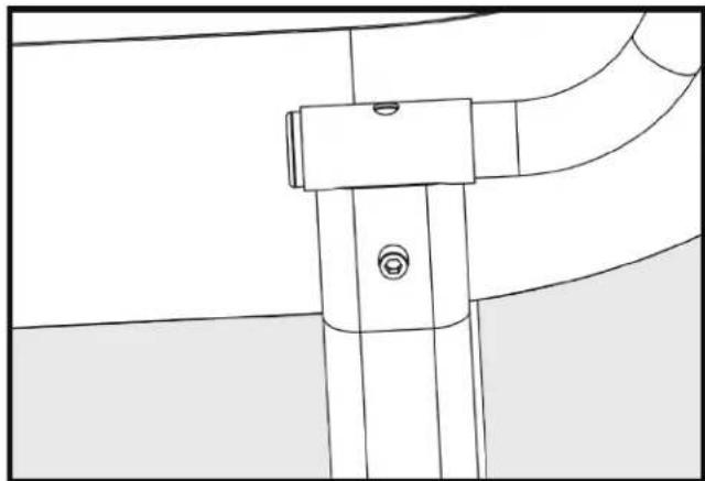
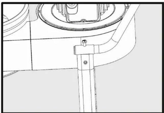
- Align holes on front support assembly to blower housing assembly (Fig 7).
natural_image
Technical line drawing of a mechanical component with no visible text or symbolsFIGURE 7
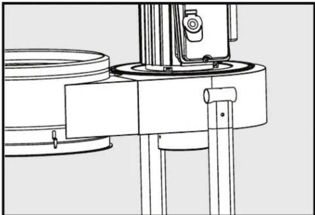
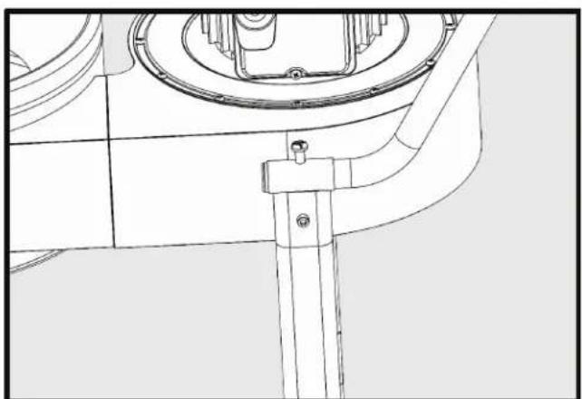
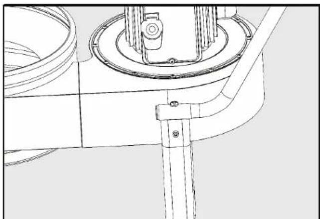
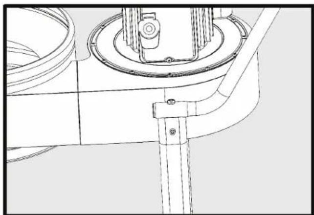
- Insert M8 x 55mm hex socket head screw (24) through hole and thread into blower housing (Fig 8).
- Tigten screw.
- Repeat on other side.
natural_image
Technical line drawing of a mechanical device with gears and a central housing (no text or symbols)FIGURE 8
ASSEMBLY (continued)
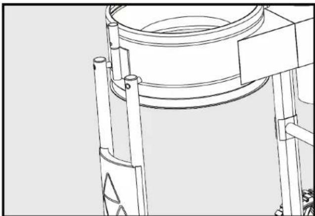
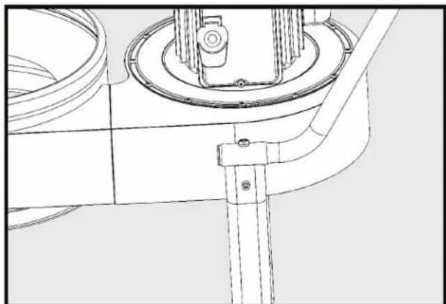
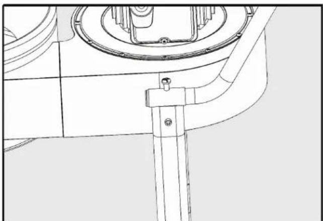
- Place M6 hex socket head screw (23) through hole of blower housing bracket and thread into rear blower housing support (Fig 9).
- Tigten screw.
- Repeat on other side.
natural_image
Technical line drawing of a mechanical assembly with no visible text or symbolsFIGURE 9
ATTACHING HANDLE
- Insert handle into both brackets on blower housing (Fig 10).
- Align holes in handle with top holes in blower housing brackets.
- Screw in M8 Phillips head self tapping screw (21) on both sides (Fig 11).
- Insert tube end cap into end of handle.
- Be sure cap is seated (Fig 12).
- Repeat on other side.
natural_image
Pure technical line drawing of a mechanical component without any text, numbers, or symbolsFIGURE 10
natural_image
Technical line drawing of a mechanical component with no visible text or symbolsFIGURE 11
natural_image
Technical line drawing of a mechanical assembly with no visible text or symbolsFIGURE 12
ATTACHING THE DUST INTAKE PORTS
WARNING
Disconnect the machine from the power source!
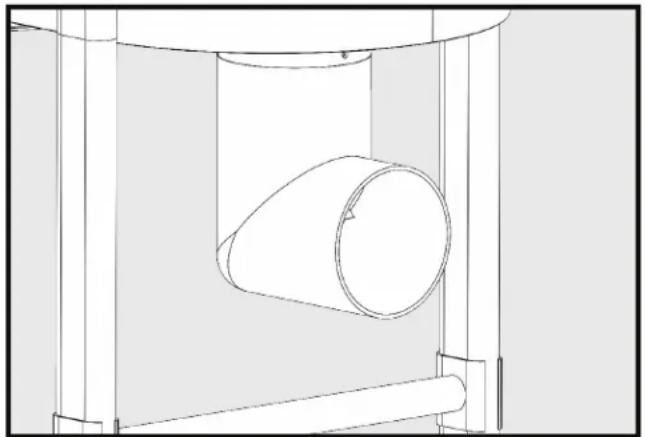
- Place the inlet adapter on the dust intake port as shown in Fig. 13 opposite to the motor. Make sure that the inlet adapter fits on the intake flange and holes line up between the inlet adapter and housing.
- Insert screws (25).
- Tighten screws on both sides.
natural_image
Technical line drawing of a cylindrical component inside a mechanical housing (no text or symbols)FIGURE 13
NOTE:
Do not attach hose directly to inlet without having the adapter, 90° elbow, in place.
Not using the adapter could cause damage to the hose and affect airflow into the collector.
ASSEMBLY (continued)
ATTACHING THE DUST COLLECTION BAG
WARNING Disconnect the machine from the power source!
A. USING CLOTH COVERED FLEXIBLE RING:
- Place the cloth-covered bag retainer ring (8) inside the opening of the clear plastic dust collection bag (6). Fold about 6 inches of the bag around the retainer ring (Fig 14).
- Place the bag in the large hole in the blower housing assembly. Fit the retainer ring into the bottom groove. Bend and fold the ring to fit it into place. Flexible ring will fit into the bottom of the blower housing the same way as described for installation of the Micron bag in the top of the blower housing. Refer to Fig 18 & Fig 19 on pg 15.
- Tug slightly on the bag to eliminate any slack and to make sure that the bag is secure and will not detach during collection.

natural_image
Person holding a transparent plastic bag containing a white paper or plastic container (no text or symbols visible)FIGURE 14
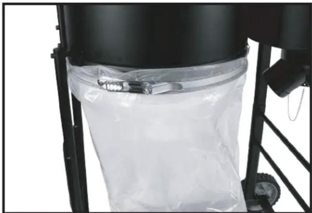
B. USING A METAL BAG CLAMP
You can also attach the plastic bag to the outside of the dust collector using the included clamp Fig 15.
- Slide the bag under the hooks.
- Place the clamp around the top of the plastic bag (6). Folding over a few inches of plastic bag over the clamp (11).
- Secure the clamp making sure the clamp isn't over the hook.
natural_image
Close-up of a black industrial machine with a transparent plastic bag attached, no visible text or symbolsFIGURE 15
ASSEMBLY (continued)
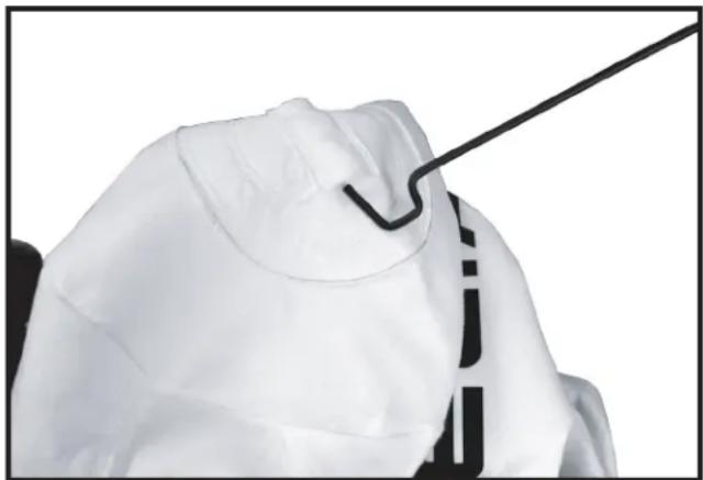
ATTACHING THE TOP FILTER BAG
WARNING
Disconnect the machine from the power source!
- Insert the hanger rod hook (12) through the material on top of the filter bag (Fig 16).
natural_image
Close-up of a medical or surgical device with a black tool inserted, showing no visible text or symbols.FIGURE 16
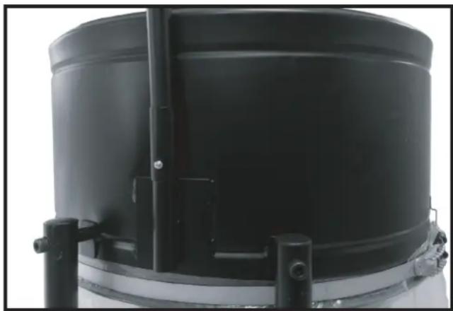
- Insert the assembled hanger rod assembly into the hanger bracket ensuring that the lock button is in place and secure as shown in (Fig 17).
natural_image
Close-up of a black cylindrical industrial container with metal brackets and mounting feet (no visible text or symbols)FIGURE 17
ASSEMBLY (continued)
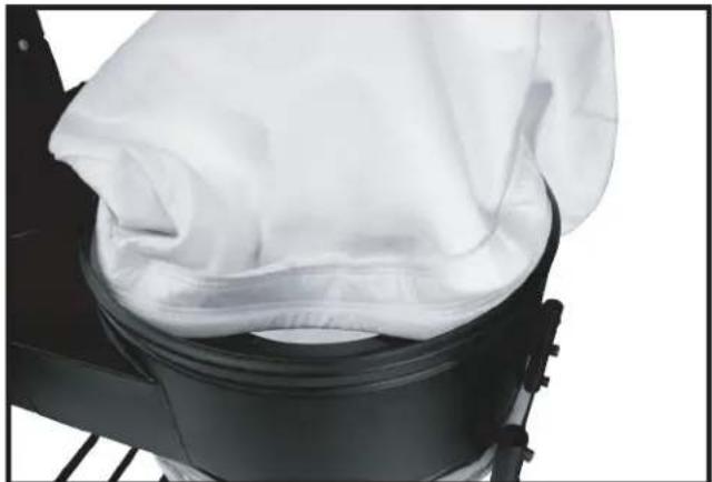
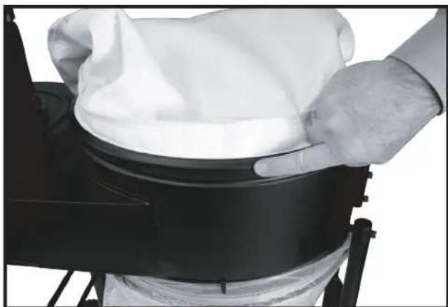
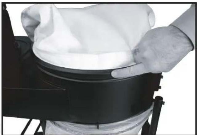
- Work the open end of the filter bag (7) into the top groove of the dust collector drum until it is secure and sealed. Bend and fold, as necessary, the internal bag retainer ring to fit it into place as shown in Fig 18 & 19.
NOTE: Bag ring must fit into housing groove completely to ensure a proper seal with no leaks.
natural_image
Close-up of a black mechanical device with a white cloth partially covered, showing internal components (no text or symbols visible)FIGURE 18
natural_image
Person holding a white cloth over a black cylindrical object, viewed from above (no text or symbols visible)FIGURE 19
ASSEMBLY (continued)
ATTACHING THE HOSE TO THE INTAKE PORT
WARNING Disconnect the machine from the power source!
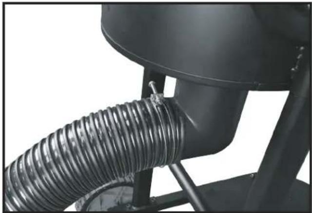
Model 50-723 T2 provides one 4" dust ports. To attach the hose (SOLD SEPARATELY):
Loosely attach the hose clamp around one end of the flexible hose (Hose sold separately). Attach the hose to the dust intake port. Tighten the hose clamp as shown in Fig 20. Attach the remaining clamp to the other end of the flexible hose and to the woodworking machine.
NOTE: Do not operate the dust collector without hose attached to the inlet adapter.
natural_image
Close-up of a mechanical component with coiled spring and cylindrical housing (no visible text or symbols)FIGURE 20
OPERATION
OPERATIONAL CONTROLS AND ADJUSTMENTS
⚠ WARNING For operator safety, do not operate the machine with any dust intake holes uncovered. The rotating fan, located inside the blower housing, is accessible through the dust intake port and can be hazardous. Always wear proper apparel. Do not wear jewelry. Keep your fingers and all foreign objects out of the dust intake port. Follow the safety rules in this manual.
STARTING AND STOPPING THE DUST COLLECTOR
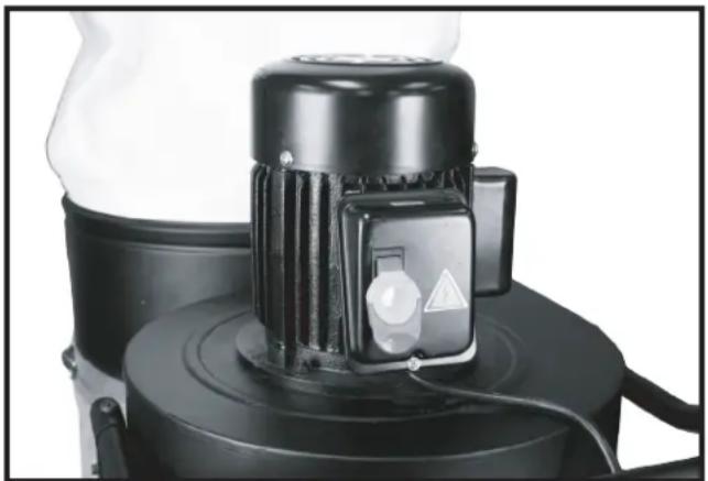
- The on/off switch Fig. 21 is located on the motor housing. To turn the machine "ON", move the switch up to the "ON" position.
- To turn the machine "OFF", move the switch (A) down to the "OFF" position.
⚠ WARNING Make sure that the switch is in the "OFF" position before plugging in the power cord. In the event of a power failure, move the switch to the "OFF" position. An accidental start-up can cause injury.
LOCKING THE SWITCH IN THE "OFF" POSITION
IMPORTANT: When the tool is not in use, the switch should be locked in the “OFF” position to prevent unauthorized use. To lock the machine, grasp the switch toggle Fig. 21 and pull it out of the switch. With the switch toggle removed (Fig 22), the switch will not operate. However, should the switch toggle be removed while the dust collector is running, the machine can be turned “OFF,” but cannot be restarted without re-inserting the key in the toggle switch.
natural_image
Close-up of a black industrial fan or pump unit with a circular control knob and triangular warning symbol (no visible text or labels)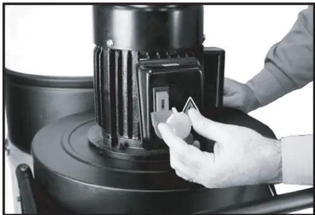
natural_image
Close-up of a hand using a tool to adjust or install a black industrial machine component (no visible text or symbols)FIGURE 22FIGURE 21
⚠ WARNING When using this dust collector, do not pick up anything that is burning, smoldering, or smoking (matches, cigarettes, or hot ashes).
⚠ WARNING Do not use this unit to vacuum combustible explosive materials (coal, grain, or other finely-divided combustible material).
⚠ WARNING Do not use this unit to vacuum hazardous, toxic, or carcinogenic materials (asbestos, pesticide, or lead-based paint debris).
TROUBLESHOOTING
For assistance with your machine, visit our website at www.DeltaMachinery.com for a list of service centers or call the DELTA® Power Equipment Corporation help line at 1-800-223-7278.
MAINTENANCE
⚠ WARNING: To reduce the risk of injury, turn unit off and disconnect it from power source before installing and removing accessories, before adjusting or when making repairs. An accidental start-up can cause personal injury.
KEEP MACHINE CLEAN
Periodically blow out all air passages with dry compressed air. All plastic parts should be cleaned with a soft damp cloth.
⚠ WARNING: NEVER use solvents to clean plastic parts. They could possibly dissolve or otherwise damage the material. Wear certified safety equipment for eye, hearing and respiratory protection while using compressed air.
FAILURE TO START
Should your machine fail to start, check to make sure the prongs on the cord plug are making good contact in the outlet. Also, check for blown fuses or open circuit breakers in the line.
SERVICE
REPLACEMENT PARTS
Use only identical replacement parts. For a parts list or to order parts, visit our website at www.DeltaMachinery.com/service. You can also order parts from your nearest factory-owned branch, Authorized Warranty Service Center or by calling Technical Service Manager at 1-800-223-7278 to receive personalized support from one of our highly-trained representatives.
FREE WARNING LABEL REPLACEMENT
If your warning labels become illegible or are missing, call 1-800-223-7278 for a free replacement.
SERVICE AND REPAIRS
All quality tools will eventually require servicing and/or replacement of parts. For information about DELTA® Power Equipment Corporation, its factory-owned branches, or to locate an Authorized Warranty Service Center, visit our website at www.DeltaMachinery.com or call our Technical Service Manager at 1-800-223-7278. All repairs made by our service centers are fully guaranteed against defective material and workmanship. We cannot guarantee repairs made or attempted by others. By calling this number you can also find answers to most frequently asked questions.
You can also write to us for information at DELTA® Power Equipment Corporation, 2651 New Cut Road, Spartanburg SC 29303 - Attention:
Technical Service Manager. Be sure to include all of the information shown on the nameplate of your tool (model number, type, serial number, date code, etc.)
ACCESSORIES
⚠ WARNING: Since accessories other than those offered by DELTA® have not been tested with this product, use of such accessories could be hazardous. For safest operation, only DELTA® recommended accessories should be used with this product.
A complete line of accessories is available from your DELTA® Supplier, DELTA® Factory Service Centers, and DELTA® Authorized Service Centers. Please visit our Web Site www.DeltaMachinery.com for an online catalog or for the name of your nearest supplier.
WARRANTY
To register your tool for warranty service visit our website at www.DeltaMachinery.com.
Five Year Limited New Product Warranty
DELTA® will repair or replace, at its expense and at its option, any new DELTA® machine, machine part, or machine accessory which in normal use has proven to be defective in workmanship or material, provided that the customer returns the product prepaid to a DELTA® factory service center or authorized service station with proof of purchase of the product within five years and provides DELTA® with reasonable opportunity to verify the alleged defect by inspection. For all refurbished DELTA® product, the warranty period is 180 days. DELTA® will not be responsible for any asserted defect which has resulted from normal wear, misuse, abuse or repair or alteration made or specifically authorized by anyone other than an authorized DELTA® service facility or representative. Under no circumstances will DELTA® be liable for incidental or consequential damages resulting from defective products. Some states do not allow the exclusion or limitation of incidental or consequential damages, so the above limitation or exclusion may not apply to you. This warranty is DELTA®'s sole warranty and sets forth the customer's exclusive remedy, with respect to defective products; all other warranties, express or implied, whether of merchantability, fitness for purpose, or otherwise, are expressly disclaimed by DELTA®. For further detail of warranty coverage and warranty repair information, visit www.DeltaMachinery.com or call 1-800-223-7278. This warranty gives you specific legal rights and you may have other rights which vary in certain states or provinces.
LATIN AMERICA: This warranty does not apply to products sold in Latin America. For products sold in Latin America, see country specific warranty information contained in the packaging, call the local company or see website for warranty information.
NOTES
DELTA®
POWER EQUIPMENT CORPORATION
1 HP DUST COLLECTOR
Dépoussièreur 1 HP
natural_image
Line drawing of a DELTA industrial machine with wheels and a cylindrical tank (no text or symbols on the device itself)50-723 T2

TABLE DES MATIÈRES
CONSIGNES DE SÉCURITÉ IMPORTANTES ..... 22
LOGOS DE SÉCURITÉ 22
RÈGLES DE SÉCURITÉ GÉNÉRALES ...... 23
RÈGLES DE SÉCURITÉ SPÉCIFIQUES SUPPLÉMENTAIRES
DESCRIPTION FONCTIONNELLE 26
CONTENU DES EMBALLAGES 27
MONTAGE 28
FONCTIONNEMENT ...... 37
DÉPANNAGE 37
ENTRETIEN 38
REPARATIONS 38
ACCESSOIRES 39
FRANÇAIS 21
ESPAÑOL 41
CONSIGNES DE SÉCURITÉ IMPORTANTES
• National Safety Council, 1121 Spring Lake Drive, Itasca, IL 60143-3201
- American National Standards Institute, 25 West 43rd Street, 4 floor, New York, NY 10036 www.ansi.org -ANSI 01.1 Safety Requirements for Woodworking Machines
• U.S. Department of Labor regulations www.osha.gov
CONSERVEZ CES INSTRUCTIONS!
LOGOS DE SÉCURITÉ
natural_image
Black industrial air purifier with fan and housing (no visible text or symbols)


natural_image
Technical line drawing of a mechanical assembly with gears and a lever (no text or symbols)FIGURE 1
ROUES ARRIÈRES
natural_image
Technical line drawing of a mechanical assembly with a vertical component and a bracket (no text or symbols)FIGURE 2
MONTAGE (suite)
MONTER LE SUPPORT ARRIÈRE DU BOÎTIER DE SOUFFLEUR
natural_image
Technical line drawing of a mechanical frame assembly with two tires, no text or symbols presentFIGURE 3
MONTER LE MODULE DE SUPPORT FRONTAL
natural_image
Technical line drawing of a mechanical device with wheels and legs (no text or symbols)FIGURE 4
MONTER LE SUPPORT TRANSVERSAL ARRIÈRE DU SOCLE
natural_image
Technical line drawing of a wheeled cart with tires and wheels, no text or symbols presentFIGURE 5
MONTAGE (suite)
MONTER LE MODULE MOTEUR-SOUFFLEUR
REMARQUE : DEUX PERSONNES SONT NÉCESSAIRES POUR CETTE OPÉRATION
natural_image
Technical line drawing of a mechanical assembly with no visible text or symbolsFIGURE 6
natural_image
Technical line drawing of a mechanical component with no visible text or symbolsFIGURE 7
natural_image
Technical line drawing of a mechanical device with gears and a central housing (no text or symbols)FIGURE 8
MONTAGE (suite)
natural_image
Technical line drawing of a mechanical assembly with no visible text or symbolsFIGURE 9
MONTER LA POIGNÉE
natural_image
Technical line drawing of a mechanical component with curved and straight sections (no text or symbols)FIGURE 10
natural_image
Technical line drawing of a mechanical component with no visible text or symbolsFIGURE 11
natural_image
Technical line drawing of a mechanical assembly with no visible text or symbolsFIGURE 12
MONTER LES QRIFICES D'ADMISSION DE LA POUSSIÈRE

AVERTISSEMENT
natural_image
Technical line drawing of a cylindrical component inside a mechanical housing (no text or symbols)FIGURE 13
REMARQUE:
natural_image
Person holding a transparent plastic bag containing a white material, viewed from above (no text or symbols visible)FIGURE 14
B. UTILISATION D'UNE BRIDE MÉTALLIQUE DE SAC :
natural_image
Close-up of a black industrial machine with transparent plastic cover and mechanical components (no visible text or symbols)FIGURE 15
MONTAGE (suite)
FIXATION DU SAC FILTRANT SUPÉRIEUR

AVERTISSEMENT
natural_image
Close-up of a medical or surgical procedure in progress, showing a needle inserted into tissue (no text or symbols visible)FIGURE 16
natural_image
Close-up of a black cylindrical industrial container with metal brackets and a side-mounted pipe (no visible text or symbols)FIGURE 17
MONTAGE (suite)
natural_image
Close-up of a black mechanical device with a white cloth partially covered, showing internal components (no text or symbols visible)FIGURE 18

natural_image
Person handling a white cloth over a black cylindrical object, possibly a container or device (no visible text or symbols)FIGURE 19
MONTAGE (suite)
RACCORD DU TUYAU À L'ORIFICE D'ADMISSION
AVERTISSEMENT
natural_image
Close-up of a mechanical component with coiled spring and cylindrical shaft (no visible text or symbols)FIGURE 20
FONCTIONNEMENT
CONTRÔLES DE FONCTIONNEMENT ET RÉGLAGES
natural_image
Close-up of a black industrial fan or pump unit with a circular control knob and warning symbol (no readable text)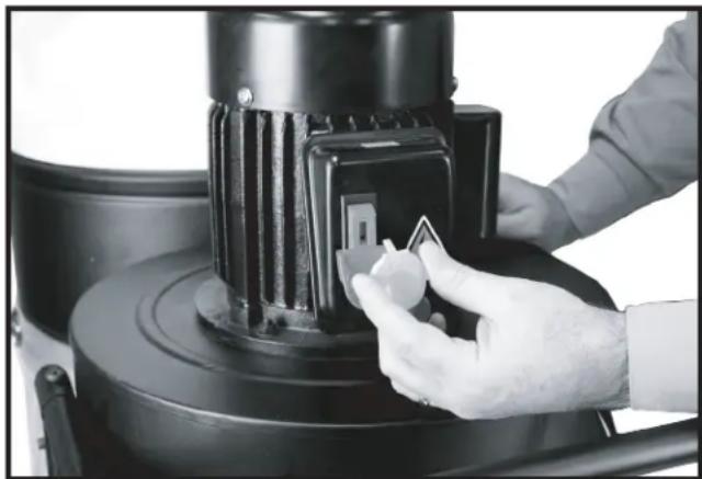
natural_image
Close-up of a hand adjusting a black industrial machine component with a small inset showing a white tag (no visible text or symbols)FIGURE 22FIGURE 21
natural_image
Line drawing of a DELTA industrial machine with wheels and control panel (no text or symbols on the device itself)Français (21)
Español (41)
Instruction manual
LEA ESTE MANUAL ANTES
DE USAR EL PRODUCTO.
50-723 T2

TABLA DE CONTENIDO
natural_image
Black industrial air purifier with fan and housing (no visible text or symbols)
natural_image
Technical line drawing of a mechanical clamp or bracket assembly (no text or symbols)FIGURA 1
ACOPLAR LAS RUEDAS TRASERAS
natural_image
Technical line drawing of a mechanical assembly with two components: a vertical grooved part and a horizontal bracket (no text or symbols)FIGURA 2
natural_image
Technical line drawing of a mechanical frame assembly with wheels and a hanging component (no text or symbols)FIGURA 3
ACOPLAR EL CONJUNTO DE SOPORTE FRONTAL
natural_image
Technical line drawing of a mechanical device with wheels and mounting brackets (no text or symbols)FIGURA 4
ACOPLAR EL SOPORTE CRUZADO TRASERO
natural_image
Technical line drawing of a wheeled cart with visible wheels and side supports (no text or symbols)FIGURA 5
natural_image
Technical line drawing of a mechanical assembly with no visible text or symbolsFIGURA 6
natural_image
Technical line drawing of a mechanical component with no visible text or symbolsFIGURA 7
natural_image
Technical line drawing of a mechanical device with gears and a central housing (no text or symbols)FIGURA 8
natural_image
Technical line drawing of a mechanical assembly with no visible text or symbolsFIGURA 9
ACOPLAR EL ASA
natural_image
Technical line drawing of a pipe fitting with a circular component and mounting holes (no text or symbols)FIGURA 10
natural_image
Technical line drawing of a mechanical component with no visible text or symbolsFIGURA 11
natural_image
Technical line drawing of a mechanical assembly with no visible text or symbolsFIGURA 12
natural_image
Technical line drawing of a cylindrical component inside a mechanical housing (no text or symbols)FIGURA 13
NOTA:
natural_image
Close-up of hands holding a transparent plastic bag containing a white circular object (no text or symbols visible)FIGURA 14
B. USANDO UNA ABRAZADERA METÁLICA PARA LAS BOLSAS
natural_image
Close-up of a black industrial machine with a transparent plastic bag attached, mounted on a metal frame (no visible text or symbols)FIGURA 15
natural_image
Close-up of a white garment with a black string being inserted, no visible text or symbolsFIGURA 16
natural_image
Close-up of a black cylindrical industrial container with metal brackets and mounting feet (no visible text or symbols)FIGURA 17
natural_image
Close-up of a black mechanical device with a white cloth partially covered, showing internal components (no text or symbols visible)FIGURA 18
natural_image
Person handling a white cloth over a black cylindrical object, possibly a container or device (no visible text or symbols)FIGURA 19
natural_image
Close-up of a mechanical component with coiled spring and cylindrical housing (no visible text or symbols)FIGURA 20
MANEJO
natural_image
Close-up of a black industrial fan or scrubber with a circular vent and warning symbol (no visible text or labels)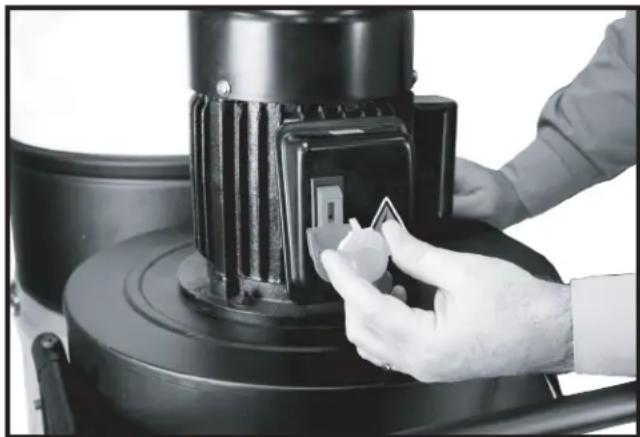
natural_image
Close-up of a gloved hand adjusting a black industrial machine component (no visible text or symbols)FIGURA 22FIGURA 21
Copyright © 2016 DELTA® Power Equipment Corporation DPEC004416
Issued: 04-19-16
Revised: 10-25-16

- TABLE OF CONTENTS
- IMPORTANT SAFETY INSTRUCTIONS
- SAFETY GUIDELINES - DEFINITIONS
- WARNING:
- GENERAL SAFETY RULES
- ADDITIONAL SPECIFIC SAFETY RULES
- ⚠ WARNING: DO NOT USE THIS UNIT TO FILTER
- WARNING: DO NOT USE THIS UNIT TO
- SAVE THESE INSTRUCTIONS.
- Refer to them often and use them to instruct others.
- POWER CONNECTIONS
- MOTOR SPECIFICATIONS
- GROUNDING INSTRUCTIONS
- All grounded, cord-connected machines:
- Grounded, cord-connected machines intended for use on a supply circuit having a nominal rating less than 150 volts:
- EXTENSION CORDS
- FUNCTIONAL DESCRIPTION
- FOREWORD
- CARTON CONTENTS
- ASSEMBLY
- ASSEMBLY TIME ESTIMATE
- ATTACHING THE CASTERS
- ATTACHING THE REAR WHEELS
- ASSEMBLY (continued)
- ATTACHING REAR BLOWER HOUSING SUPPORT
- ATTACHING FRONT SUPPORT ASSEMBLY
- ATTACHING REAR STAND CROSS SUPPORT
- ATTACHING MOTOR BLOWER ASSEMBLY TO STAND
- ATTACHING HANDLE
- ATTACHING THE DUST INTAKE PORTS
- WARNING
- NOTE:
- ATTACHING THE DUST COLLECTION BAG
- WARNING Disconnect the machine from the power source!
- USING CLOTH COVERED FLEXIBLE RING:
- USING A METAL BAG CLAMP
- ATTACHING THE TOP FILTER BAG
- ATTACHING THE HOSE TO THE INTAKE PORT
- OPERATION
- OPERATIONAL CONTROLS AND ADJUSTMENTS
- STARTING AND STOPPING THE DUST COLLECTOR
- LOCKING THE SWITCH IN THE "OFF" POSITION
- TROUBLESHOOTING
- MAINTENANCE
- KEEP MACHINE CLEAN
- FAILURE TO START
- SERVICE
- REPLACEMENT PARTS
- FREE WARNING LABEL REPLACEMENT
- SERVICE AND REPAIRS
- ACCESSORIES
- WARRANTY
- Five Year Limited New Product Warranty
- NOTES
- DELTA®
- POWER EQUIPMENT CORPORATION
- HP DUST COLLECTOR
- TABLE DES MATIÈRES
- CONSIGNES DE SÉCURITÉ IMPORTANTES
- LOGOS DE SÉCURITÉ
- ROUES ARRIÈRES
- MONTAGE (suite)
- MONTER LE SUPPORT ARRIÈRE DU BOÎTIER DE SOUFFLEUR
- MONTER LE MODULE DE SUPPORT FRONTAL
- MONTER LE SUPPORT TRANSVERSAL ARRIÈRE DU SOCLE
- MONTER LE MODULE MOTEUR-SOUFFLEUR
- MONTER LA POIGNÉE
- MONTER LES QRIFICES D'ADMISSION DE LA POUSSIÈRE
- AVERTISSEMENT
- REMARQUE:
- UTILISATION D'UNE BRIDE MÉTALLIQUE DE SAC :
- FIXATION DU SAC FILTRANT SUPÉRIEUR
- RACCORD DU TUYAU À L'ORIFICE D'ADMISSION
- FONCTIONNEMENT
- CONTRÔLES DE FONCTIONNEMENT ET RÉGLAGES
- TABLA DE CONTENIDO
- ACOPLAR LAS RUEDAS TRASERAS
- ACOPLAR EL CONJUNTO DE SOPORTE FRONTAL
- ACOPLAR EL SOPORTE CRUZADO TRASERO
- ACOPLAR EL ASA
- NOTA:
- USANDO UNA ABRAZADERA METÁLICA PARA LAS BOLSAS
- MANEJO
Brand : DELTA
Model : 50-723 T2
Category : Industrial vacuum cleaner