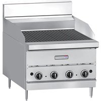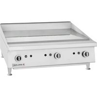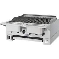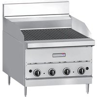
G48 BRL - Grill plate GARLAND - Free user manual and instructions
Find the device manual for free G48 BRL GARLAND in PDF.


User questions about G48 BRL GARLAND
0 question about this device. Answer the ones you know or ask your own.
Ask a new question about this device
Download the instructions for your Grill plate in PDF format for free! Find your manual G48 BRL - GARLAND and take your electronic device back in hand. On this page are published all the documents necessary for the use of your device. G48 BRL by GARLAND.
USER MANUAL G48 BRL GARLAND
INSTALLATION AND OPERATION MANUAL
GARLAND G-BRL & GF-BRL SERIES BROILERS




Only GF Series Broilers are CE Approved
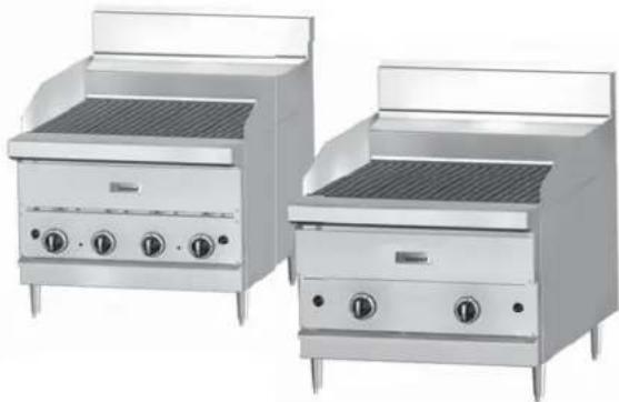
natural_image
Two identical stainless steel electric cookers with heat sinks and control knobs, shown from different angles (no text or labels visible)Includes Models: G18-BRL, G24-BRL, G30-BRL, G36-BRL, G48-BRL, GF18-BRL, GF24-BRL, GF30-BRL and GF36-BRL
Français ...... Pg 15
Español ...... Pg 29
FOR YOUR SAFETY:
DO NOT STORE OR USE GASOLINE
OR OTHER FLAMMABLE VAPORS OR
LIQUIDS IN THE VICINITY OF
THIS OR ANY OTHER
APPLIANCE
WARNING:
IMPROPER INSTALLATION, ADJUSTMENT,ALTERATION, SERVICE OR MAINTENANCECAN CAUSE PROPERTY DAMAGE, INJURY,OR DEATH. READ THE INSTALLATION,OPERATING AND MAINTENANCEINSTRUCTIONS THOROUGHLYBEFORE INSTALLING ORSERVICING THIS EQUIPMENT
PLEASE READ ALL SECTIONS OF THIS MANUAL AND RETAIN FOR FUTURE REFERENCE.
THIS PRODUCT HAS BEEN CERTIFIED AS COMMERCIAL COOKING EQUIPMENT AND MUST BE INSTALLED BY PROFESSIONAL PERSONNEL AS SPECIFIED.
IN THE COMMONWEALTH OF MASSACHUSETTS THIS PRODUCT MUST BE INSTALLED BY A LICENSED PLUMBER OR GAS FITTER.
For Your Safety:
Post in a prominent location, instructions to be followed in the event the user smells gas. This information shall be obtained by consulting your local gas supplier.
Users are cautioned that maintenance and repairs must be performed by a Garland authorized service agent using genuine Garland replacement parts. Garland will have no obligation with respect to any product that has been improperly installed, adjusted, operated or not maintained in accordance with national and local codes or installation instructions provided with the product, or any product that has its serial number defaced, obliterated or removed, or which has been modified or repaired using unauthorized parts or by unauthorized service agents.
For a list of authorized service agents, please refer to the Garland web site at http://www.garland-group.com.
The information contained herein, (including design and parts specifications), may be superseded and is subject to change without notice.
GARLAND COMMERCIAL RANGES, LTD.
1177 Kamato Road, Mississauga, Ontario L4W 1X4
CANADA
Phone: 905-624-0260
Fax: 905-624-5669
General Inquires 1-905-624-0260
USA Sales 1-800-424-2411
Canadian Sales 1-888-442-7526
Canada or USA Parts/Service 1-844-724-2273
WARNING:
This product contains chemicals known to the State of California to cause cancer and/or birth defects or other reproductive harm. Installation and servicing of this product could expose you to airborne particles of glass wool/ceramic fibers. Inhalation of airborne particles of glass wool/ceramic fibers is known to the State of California to cause cancer. Operation of this product could expose you to carbon monoxide if not adjusted properly. Inhalation of carbon monoxide is known to the State of California to cause birth defects or other reproductive harm.
Keep appliance area free and clear of combustibles.
TABLE OF CONTENTS
IMPORTANT INFORMATION....2
DIMENSIONS AND SPECIFICATIONS – BROILERS....4
North America & General International Markets. 4
Australian Market 4
CE Aproved Models ....5
Pressure Settings/Injector Size 5
Heat Input 5
Gas Inlet Size....5
GF Series CE Approved Gas Categories 5
Approximate Total Input Ratings With All Burners Operating At LOW....5
DIMENSIONS AND SPECIFICATIONS – STANDS 6
PRE INSTALLATION....7
Unpacking....7
Safety Information....7
INSTALLATION....7
Rating Plate Location....7
Statutory Regulations....7
Australia Specific Regulation 7
Gas Supply 8
Gas Connections....8
Counter Line Installations 8
Location 8
Sanitary Counter Top Seal....8
Leg Installation....9
Assembly Of Counter Stand 9
Installation for Units Equipped with Casters 10
Cabinet Bases 10
Assembly Of Broiler 10
Ventilation....10
OPERATION....11
Grid Rack Seasoning Instructions 11
Lighting Instructions....11
CLEANING AND MAINTENANCE....12
Cleaning Care of the Grid Racks....12
Exterior Finish Cleaning 12
DIMENSIONS AND SPECIFICATIONS – BROILERS
| Product Dimensions and Shipping Specializations | North American and CE ^1 Inputs | |||||||
| Model W | dth | HeightW/O Legs | Depth | Shipping | No ofUHFINW/Hr | Total Input Ratings | ||
| Ibs/kg | Cu Ft BT | |||||||
| G18-BRL 18" (457mm) 25-1/8" (636mm) 34-1/2" (876mm) 190/86 21 3 45,000 13.2 | ||||||||
| G24-BRL | 24" (610mm) | 25-1/8" (636mm) | 34-1/2" (876mm) | 240/109 | 21 | 4 | 60,000 | 17.6 |
| G30-BRL | 30" (762mm) | 25-1/8" (636mm) | 34-1/2" (876mm) | 290/131 | 29.5 | 5 | 75,000 | 22 |
| G36-BRL | 36" (914mm) | 25-1/8" (636mm) | 34-1/2" (876mm) | 340/154 | 29.5 | 6 | 90,000 | 26.4 |
| G48-BRL | 48" (1219mm) | 25-1/8" (636mm) | 34-1/2" (876mm) | 375/170 | 37 | 8 | 120,000 | 35.2 |
| ^1 GF18-BRL | 8" (457mm) 25-1/8" (636mm) 34-1/2" (876mm) 190/86 21 3 45,000 12.0 | |||||||
| ^1 GF24-BRL | 24" (610mm) | 25-1/8" (636mm) | 34-1/2" (876mm) | 240/109 | 21 | 4 | 60,000 | 16.0 |
| ^1 GF30-BRL | 30" (762mm) | 25-1/8" (636mm) | 34-1/2" (876mm) | 290/131 | 29.5 | 5 | 75,000 | 20.0 |
| ^1 GF36-BRL | 36" (914mm) | 25-1/8" (636mm) | 34-1/2" (876mm) | 340/154 | 29.5 | 6 | 90,000 | 24.0 |
| ^1 NOTE: Only GF series broilers with flame failure features are CE approved. | ||||||||
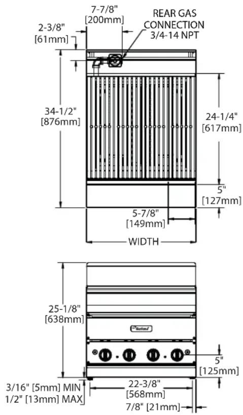
G-BRL Models
For use in non-combustible locations only.
| Installation Clearances From Non Combustible Materials (all models) | |
| Rear | Sides |
| 0" | 0" |
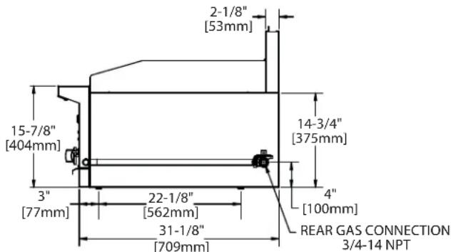
text_image
2-1/8" [53mm] 15-7/8" [404mm] 3" [77mm] 22-1/8" [562mm] 31-1/8" [709mm] 14-3/4" [375mm] 4" [100mm] REAR GAS CONNECTION 3/4-14 NPTNorth America & General International Markets
| Operating Manifold Pressure | |||
| Natural (G20) | 4.5" wc(11.2mbar) | LPG (G31) | 10" wc(24.9mbar) |
Australian Market
| Operating Manifold Pressure | |||
| Natural 4" wc (1.0kPa) | LPG 10" wc (2.49 kpa) | ||
| Input Per Burner | |||
| MJ/H | Injector Dia. | MJ/H | Injector Dia. |
| 15.8 | 1.9 mm | 15.8 | 1.1 mm |
DIMENSIONS AND SPECIFICATIONS – BROILERS continued
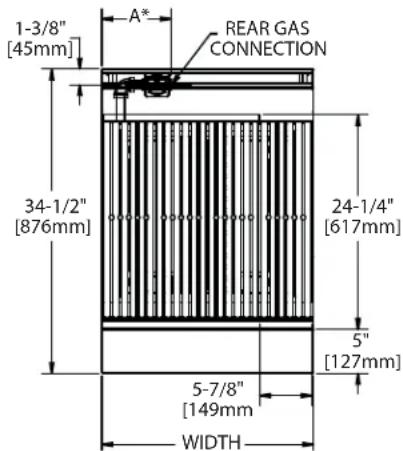
text_image
1-3/8" [45mm] A* REAR GAS CONNECTION 34-1/2" [876mm] 24-1/4" [617mm] 5" [127mm] 5-7/8" [149mm] WIDTH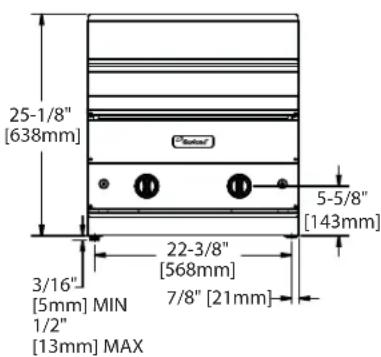
text_image
25-1/8" [638mm] 3/16" [5mm] MIN 1/2" [13mm] MAX 22-3/8" [568mm] 7/8" [21mm] 5-5/8" [143mm]GF-BRL Models
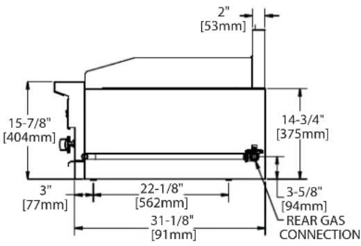
text_image
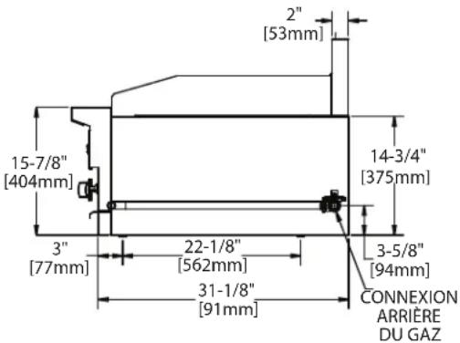
2" [53mm] 15-7/8" [404mm] 14-3/4" [375mm] 3" [77mm] 22-1/8" [562mm] 31-1/8" [91mm] 3-5/8" [94mm] REAR GAS CONNECTION*For units supplied with regulator dimension 'A' is 7-7/8" (200mm) with a 3/4" – 14 NPT connection. European (CE) units are not supplied with regulator, but include with an adaptor 3/4" –14 BSPT.
CE Aproved Models
Pressure Settings/Injector Size
| MODEL | 2nd Family, Groups H, L & E 3rd Family, Group 3P | |||||||||
| Setting Pressure | Injector Size | Setting Pressure | Injector Size | |||||||
| G20 @ 20 mbar inlet | G25 @ 25 mbar inlet | G31 @ 37/50 mbar inlet | ||||||||
| mbar “ | WC mbar | “WC DM | IS mm | mbar “ | WC DM | IS mm | ||||
| GF18-BRL | 11.2 | 4.5 | 14.9 | 6 | 50 | 1.78 | 24.9 | 10 | 58 | 1.07 |
| GF24-BRL | 11.2 | 4.5 | 14.9 | 6 | 50 | 1.78 | 24.9 | 10 | 58 | 1.07 |
| GF30-BRL | 11.2 | 4.5 | 14.9 | 6 | 50 | 1.78 | 24.9 | 10 | 58 | 1.07 |
| GF36-BRL | 11.2 | 4.5 | 14.9 | 6 | 50 | 1.78 | 24.9 | 10 | 58 | 1.07 |
Heat Input
| MODEL | 2nd Family, Groups H & E | 2nd Family, Group L | 3rd Family, Group 3P | # Of Burners | |||
| (G20 @ 20/25 mbar) NAT | (G25 @ 25 mbar) NAT | (G31 @ 37/50 mbar) PROPANE | |||||
| Per Burner / Total | Per Burner / Total | Per Burner / Total | |||||
| kW | BTU/HR | kW | BTU/HR | kW | BTU/HR | ||
| GF18-BRL | 4.0 / 12.0 | 15,000 / 45,000 | 4.0 / 12.0 | 15,000 / 45,000 | 4.0 / 12.0 | 15,000 / 45,000 | 3 |
| GF24-BRL | 4.0 / 16.0 | 15,000 / 60,000 | 4.0 / 16.0 | 15,000 / 60,000 | 4.0 / 16.0 | 15,000 / 60,000 | 4 |
| GF30-BRL | 4.0 / 20.0 | 15,000 / 75,000 | 4.0 / 20.0 | 15,000 / 75,000 | 4.0 / 20.0 | 15,000 / 75,000 | 5 |
| GF36-BRL | 4.0 / 24.0 | 15,000 / 90,000 | 4.0 / 24.0 | 15,000 / 90,000 | 4.0 / 24.0 | 15,000 / 90,000 | 6 |
Gas Inlet Size
| Model Width | Connection | Connection CE Models (ISO7-1) |
| 23-5/8" (600mm) & 35-1/2" (900mm) | 3/4" NPT Rear Gas Connection | 3/4" (19.1mm) BSPT |
GF Series CE Approved Gas Categories
| Country | Gas Category | Gas Type | Pressure (mbar) |
| GB, IE, ES, PT, GR | I2H | G20 | 20 |
| BE, FR | I2E+ | G20 | 20/25 |
| DE | I2E | G20 | 20 |
| GB, IE, ES, PT, BE, FR I3P | G31 | 37 | |
| GB, FR, NL, DE, ES I3P | G31 | 50 | |
| NL | I3P | G31 | 30 |
Approximate Total Input Ratings With All Burners Operating At Lo
| kW | BTU/h | |
| GF18-BRL | 4.5 | 16,875 |
| GF24-BRL | 6.0 | 22,500 |
| GF30-BRL | 7.5 | 28,125 |
| GF36-BRL | 9.0 | 33,750 |
DIMENSIONS AND SPECIFICATIONS – STANDS
| Model Number | Description | Use With Broiler Model | Cu. Ft. | Ship Weight Lb/ Kg |
| G18-BRL-STD | Floor Stand 18" (457mm) Wide G18-BRL & GF18-BRL 4.5 30/14 | |||
| G24-BRL-STD | Floor Stand 24" (610mm) Wide G24-BRL & GF24-BRL 4.5 40/18 | |||
| G30-BRL-STD | Floor Stand 30" (762mm) Wide G30-BRL & GF30-BRL 4.5 50/23 | |||
| G36-BRL-STD | Floor Stand 36" (914mm) Wide G36-BRL & GF36-BRL 4.5 55/25 | |||
| G48-BRL-STD | Floor Stand 48" (1219mm) Wide G48-BRL 5.5 58/26 | |||
| G18-BRL-CAB | Closed Cabinet 18" (457mm) Wide G18-BRL & GF18-BRL 21 40/18 | |||
| G24-BRL-CAB | Closed Cabinet 24" (610mm) Wide G24-BRL & GF24-BRL 21 45/20 | |||
| G30-BRL-CAB | Closed Cabinet 30" (762mm) Wide G30-BRL & GF30-BRL 29.5 50/23 | |||
| G36-BRL-CAB | Closed Cabinet 36" (914mm) Wide G36-BRL & GF36-BRL 29.5 60/27 | |||
| G48-BRL-CAB | Closed Cabinet 48" (1219mm) Wide | G48-BRL | 37 65/29.5 |
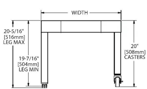
text_image
WIDTH 20-5/16" [516mm] LEG MAX 19-7/16" [504mm] LEG MIN 20" [508mm] CASTERS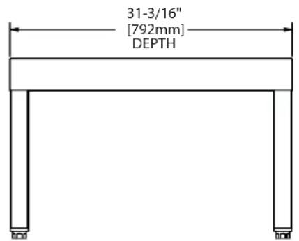
text_image
31-3/16" [792mm] DEPTHG24-BRL-STD
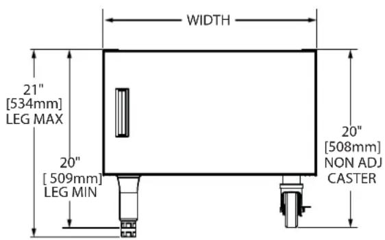
text_image
WIDTH 21" [534mm] LEG MAX 20" [509mm] LEG MIN 20" [508mm] NON ADJ CASTER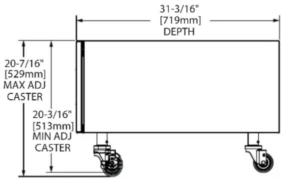
text_image
31-3/16" [719mm] DEPTH 20-7/16" [529mm] MAX ADJ CASTER 20-3/16" [513mm] MIN ADJ CASTERG24-BRL-CAB
• Many local codes exist, and it is the responsibility of the Owner and the Installer to comply with those codes.
- Garland reserves the right to change or improve product specifications without notification.
- Garland products are not approved or authorized for home or residential use, but are intended for commercial applications only. Garland will not provide service, warranty, maintenance or support of any kind other than in commercial applications.
PRE INSTALLATION
Unpacking
GARLAND strongly recommends this unit be inspected for possible freight damage while carrier driver is on site.
- Remove carton. In case of damage, all packing materials must be retained for carrier inspection.
- Carefully inspect the broiler for any physical signs of damage, such as scratches, dents and missing knobs.
- With carrier driver on your site, note damage on freight bill. Call carrier for inspection.
If you are checking equipment after carrier has departed, you have approximately fifteen (15) days to request a freight damage inspection be made by the carrier's agent.
If concealed damage claim is fi led with carrier beyond 15 days, GARLAND cannot be held responsible and carrier will make it incumbent upon the consignee to offer reasonable evidence that the carrier was at fault.
Safety Information
WARNING: Accessible parts may become hot during use. Young children should be kept away.
This appliance is for professional use and should only be used by qualified personnel.
This appliance is not intended for use by persons (including children) with reduced physical, sensory or mental capabilities, or lack of experience and knowledge, unless they have been given supervision or instruction concerning use of the appliance by a person responsible for their safety.
INSTALLATION
When corresponding with the factory or your local authorized factory service center regarding service problems or replacement parts, be sure to refer to the particular unit by the correct model number (including the prefix and suffix letters and numbers) and the warranty serial number. The rating plate affixed to the unit contains this information.
We suggest installation, maintenance, and repairs should be performed by your local authorized service agency listed in your information manual pamphlet.
In the event you have any questions concerning the installation, use, care or service of the product, write or call our Product Service Department.
This product must be installed by professional personnel as specified. Garland/U.S. Range products are not approved or authorized for home or residential use, but are intended for commercial applications only. Garland / U.S. Range will not provide service, warranty, maintenance, or support of any kind other than in commercial applications.
Rating Plate Location
The rating plate is located by removing the grease tray, it is located on left hand side grease slide support.
Statutory Regulations
Installation must be carried out by a competent person and in accordance with the relevant regulations, codes of practice and the related publications of the country of destination.
In European countries, installation must be carried out by a competent person and in accordance with the relevant regulations, codes of practice and the related publications of the country of destination.
In The United States of America, the installation must conform to the National Fuel Gas Code ANSI Z223.1, or latest edition, NFPA No.54 - latest edition/or local code to assure safe and efficient operation. In Canada, the installation must comply with CSA B149.1 and local codes.
Australia Specifi c Regulation
This appliance must be installed in accordance with the manufacturer's instructions, local gas fi tting regulations and requirements of AS 5601/AG 601 installation code. All burner adjustments and setting should be made by a qualifi ed gas technician.
Gas Supply
A. The type of gas for which the unit is equipped is stamped on the rating plate. Connect a unit stamped "NAT" only to natural gas; connect those stamped "PRO" only to propane gas.
B. If it is a new installation, have gas authorities check meter size and piping to assure that the unit is supplied with sufficient amount of gas pressure required to operate the unit.
C. If it is additional equipment or replacement, have a qualified gas technician check the gas pressure to make certain that existing gas facilities (meter, piping, etc.) will deliver the BTU'S of gas required at the unit with no more than 1/2" water column pressure drop. When checking pressure, be certain that other equipment on the same gas line is on at full rate.
NOTE: When checking pressure, be sure that all other equipment on the same gas line is on. If the broiler has been supplied with a regulator it has been preset to match specifications on the unit's rating plate. All units require regulators and should be adjusted accordingly to manufacturer specifications.
D. The appliance and its individual shut off (supplied by others) must be disconnected from the gas supply piping system during any pressure testing of that system at pressures in excess of 1/2 PSI (3.45 KPa).
E. Gas supply connection is made in back lower left hand corner of unit. A readily accessible approved type of hand valve should be installed on each supply line. Test for leaks – Do Not Use An Open Flame.
F. A pressure tap plug is supplied with the units and it is installed on the manifold. The valve panel must be removed to use the pressure tap. The gas pressure must be checked when the unit is installed, to insure that the unit gas pressure is the same as specified on the rating plate. If necessary, pressure adjustments must be made at the pressure regulator.
G. If it is a completely new installation, have gas lines, meter size piping and piping installed and checked by a qualified gas technician.
H. Make certain that the new piping, joints, and connections have been made in a clean manner and have been purged, so that the piping compound, chips, etc., will not clog pilots, valves, and/or controls. Use pipe joint sealant that is resistant to liquefi ed petroleum gas.
WARNING: Check gas connections for leaks. Use a soap solution or similar means. Do Not Use An Open Flame!
Gas Connections
All broilers have a rear gas 3/4" NPT or 3/4"-14NPT connections. CE models have 3/4"-14 BSPT thread adapter.
NOTE: Adequate clearance must be provided for servicing and proper operation.
Counter Line Installations
Location
Unpack units carefully and provide the necessary space on counter or back bar. All units must be installed in non-combustible locations.
A. Location of the unit should be in an area where make-up air is available to support proper combustion. Make-up air should be supplied in such a manner as to pass through the front of the unit. Do not obstruct front-air flow.
B. In accordance with standard gas appliance operation, the unit should be located under a ventilation hood of applicable size and capacity. See ventilation instructions.
Sanitary Counter Top Seal
When the broiler is installed on a counter top, the National Sanitation Foundation, (NSF), recommends that it be sealed in accordance with NSF standards per the following instructions:
- Unit should be located on a non-combustible, level counter top surface.
- Thoroughly clean the bottom perimeter of the broiler and the counter top around the bottom of the broiler.
- Apply a generous bead of silicone sealant around the entire outside perimeter of the broiler bottom.
- The broiler can be secured to the counter top by inserting the 3/8-inch diameter crating bolts through the counter from the bottom, (via predrilled 1/2" diameter holes), and threading them into the nut inserts in the bottom of the unit.
- Smooth the silicone sealant with a finger or tool to provide a cover seal.
INSTALLATION continued
Leg Installation
- All units are shipped with N.S.F. approved legs. These legs must be installed to provide a minimum clearance of four (4) inches between the counter top and bottom of the unit in order to meet National Sanitation Foundation requirements.
- When using the legs described above, raise front of unit and screw leg into leg retaining nut provided at each corner of unit, repeat at rear.
- Unit may be leveled by adjusting legs. Use a spirit level and level unit (by cooking grids) four (4) ways: across the front and back and down the sides.
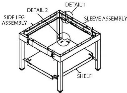
Assembly Of Counter Stand
text_image
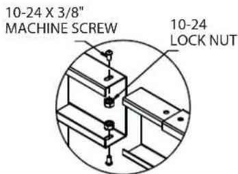
DETAIL 1 DETAIL 2 SIDE LEG ASSEMBLY SLEEVE ASSEMBLY SHELF- Slide the side leg assembly into the sleeve assembly and fasten with a screw and a nut in 8 places (2 per joint) as shown in detail 1.
text_image
10-24 X 3/8" MACHINE SCREW 10-24 LOCK NUTDETAIL 1
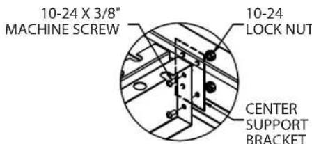
- Place the center support bracket inside of the sleeve assembly. Mount the center support to the bracket with 2 screws and nuts (detail 2). Repeat for the other side. Sleeve assemblies should be sandwiched between the center support and center support bracket. Repeat for other center support.
text_image
10-24 X 3/8" MACHINE SCREW 10-24 LOCK NUT CENTER SUPPORT BRACKETDETAIL 2
- Prior to placing the unit on the stand:
a. Remove levelling feet from unit. b. Remove grates/rods/burners etc. to lighten unit and team lift onto stand.
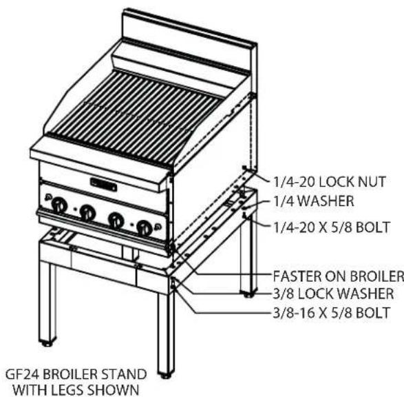
- Attach the broiler to the stand at the back with (2) 1/4" bolts, washers and lock nuts as shown. (One for each corner.)
NOTE: for 48" broiler there are (4) mounting locations at the back.
text_image
1/4-20 LOCK NUT 1/4 WASHER 1/4-20 X 5/8 BOLT FASTER ON BROILER 3/8 LOCK WASHER 3/8-16 X 5/8 BOLT GF24 BROILER STAND WITH LEGS SHOWN- Attach the broiler to the stand at the front with (2) 3/8" bolts & lock washers as shown. Bolt with thread into fasteners attached to the bottom side of the broiler (one for each corner).
NOTE: for 48" broiler there are (4) mounting locations at the back.
Installation for Units Equipped with Casters
A. The installation shall be made with a connector that complies with the Standard for Connectors for Moveable Gas Appliances, ANSI Z21.69/CSA 6.16, Addenda Z21.69B-2006/CSA 6.16B-2006 (or latest edition), and a quick-disconnect device that complies with the Standard for Quick Disconnects for Use with Gas Fuel, ANSI Z21.41/CSA 6.9, Addenda Z21.41A-2005/CSA 6.16A-2005 (or latest edition).
B. Raise the front of the appliance and block. Do not lay the appliance on its back.
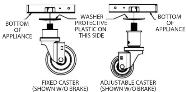
C. Caster are threaded to be easily screwed into the holes provided on the bottom of the range. It is important to add the washers supplied to help distribute force on the range when being moved.
text_image
BOTTOM OF APPLIANCE WASHER PROTECTIVE PLASTIC ON THIS SIDE BOTTOM OF APPLIANCE FIXED CASTER (SHOWN W/O BRAKE) ADJUSTABLE CASTER (SHOWN W/O BRAKE)D. Place the washer on the caster stem as shown. Since the washer is slightly cupped, it is critical that the side with the plastic is up and mates with the bottom of the appliance. With the washer in place, thread the caster onto the appliance tightly. It is not necessary to remove the plastic from the washer.
E. The front casters of the unit are equipped with brakes to limit the movement of the unit without depending on the connector and any quick-disconnect device or its associated piping to limit the appliance movement.
F. Please be aware, there is a restraint on the unit and if disconnection of the restraint is necessary, be sure to reconnect the restraint after the unit has been returned to its originally installed position.
Cabinet Bases
Cabinet base options are available for all broiler models. Cabinets are pre-assembled at time of delivery except legs or casters.
Assembly Of Broiler
Steel Grate Rods
Each broiler is supplied with (14) 15"/381mm, (18-BRL), 21"/533mm, (24-BRL), 26"/660mm, (30-BRL), 31"/787mm, (36-BRL) or 2 sets of 21"/533mm (48-BRL) long steel rods. These rods are to be installed in the grooves on the support brackets, which are atop the burners.
Briquettes
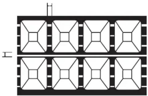
For best cooking results, it is recommended that the correct amount of briquettes are installed in the broiler. Refer to the table and drawing below for the proper arrangement of briquettes. When all the briquettes have been placed as instructed, install the top grate sections.
| MODEL 1 | B-BRL 24 | BRL 30-B | RL 36-BRL | L 48-BRL | |
| Rows front to rear | 7 | 7 | 7 | 7 | 7 |
| Rows left to right | 7 | 1 | 1 | 4 |
natural_image
Pure electrical circuit lines without any symbolsVentilation
The following notes are intended to give general guidance. For detailed recommendations, refer to the applicable code(s) in the country of destination. These appliances shall be installed in a room with sufficient ventilation to prevent the occurrence of hazardous concentrations of combustion by-products.
A good ventilation system is important for satisfactory performance and it is recommended to install the broiler under a power vented canopy.
Local and/or National Codes dictate the need of ventilation system to be used with this type of equipment. The following information is provided to give examples of available ventilation system concepts.
INSTALLATION continued
Two basic types of power ventilations are in use today. One type is the overhead hood or canopy and the other is the under shelf exhaust system. The latter offers simplicity of installation and minimum cleaning expense. Both require fl ame-proof filters for easy grease removal.
The ventilator must be connected to a duct of suitable size with an exhaust blower capable of removing a minimum of 325 CFM'S of air per square foot of broiler surface.
OPERATION
Grid Rack Seasoning Instructions
To insure long life and service, it is imperative that the cooking surface be carefully broken in or seasoned in the following manner:
- Remove all factory applied protective material by washing with hot water and a mild detergent or soap solution. Rinse and dry thoroughly.
- Apply a thin coat of olive oil or other high grade salt free cooking oil to the cooking surface. Wipe away excess.
- Turn all valves to a low setting and allow grid racks to heat slowly for thirty (30) minutes. Allow oil to remain on cooking surface three (3) to four (4) minutes, then wipe off.
- Reset valves to desired operating temperature and apply a second coat of oil and leave for two (2) or three (3) minutes after grid rack reaches temperature. Then wipe off surplus.
Your broiler is now ready to use.
NOTE: Unless products contain sufficient fat, grid racks must be seasoned before each use. Re-season after thorough cleaning of the cooking surface.
Lighting Instructions
Models G(18,24,39,36,48)-BRL
- One pilot serves two burners and is located between those burners.
- Push red spark buttons several times to ignite pilot burners.
- Ensure pilots are lit by viewing through pilot view hole on front of unit.
Models GF(18,24,30.36)-BRL
- Push in the valve knob and turn counter-clockwise to the ignition position.
- While holding the knob fully in, depress the ignitor button and visually confirm that the pilot lights are on. If the pilot does not light, repeatedly press the ignitor button until ignition is achieved.
- After the pilot is lit, continue to hold the valve knob in for at least 20 seconds, then release it. If the pilot goes out, wait fi ve, (5), minutes, then repeat the procedure.
- When the pilot is established, push in the valve knob again and turn it counter-clockwise to the full flame position, igniting the main burner.
- For low flame or simmer, push in the valve knob and turn it to the low flame position.
- To turn the burner off, push in and turn the valve knob to the circular "OFF" symbol.
Shut down
-
Turn all gas valves off.
-
If the unit is to be shut down for an extended period of time, turn the in-line service valve to the "OFF" position, (this valve is not factory supplied).
Cleaning Care of the Grid Racks
Establish a regular cleaning schedule. It is necessary to avoid obstruction and to allow proper combustion and performance.
- Grid racks should be wiped daily while still warm, using a heavy cloth or other grease absorbing material to remove grease and burnt food before they burn into the grid. Remove burnt materials, such as carbonized grease or food, with a stiff wire brush. Do Not use Any Type Of Steel wool. Small particles may be left on the grid surface and get into food products.
- Grid racks should be washed thoroughly using a wire brush and a hot, mild detergent or soap solution. Rinse with clear, warm water.
- Dry thoroughly.
- Re-season grid racks as outlined in seasoning instructions.
- Empty grease tray(s) frequently and wash daily in hot, mild detergent or soap solution.
- Do not waste gas or abuse equipment by leaving valves at high temperature settings while not in use. Throughout all idling periods, set valves as low temperature setting to keep grids warm. Re-set valves as required for periods of heavy load. Turn valves to OFF at end of daily operation.
- When the grill is running, never use objects such as sheet pans to cover the gill in order to hold in heat in an attempt to burn off grease or other debris.
Exterior Finish Cleaning
Establish a regular schedule. Any spills should be wiped off immediately.
- Wipe exposed, clean-able surface when cool with a mild detergent and hot water. Stubborn residue spots may be removed with a light weight non-metallic scouring pad. Dry thoroughly with a clean cloth.
- Stainless steel should be cleaned using a mild detergent, a soft cloth, and hot water. If it is necessary to use a non-metallic scouring pad, always rub in the direction of the grain in the metal to prevent scratching. Use a water based stainless steel cleaner (such as Drackett Twinkle), if you want a high shine.
- The side splash or main top of the broiler can be cleaned with hot water and a soap solution. A degreaser may be used as well. To make the cleaning easier, you may remove the main top assembly. To remove the main top, first lift and remove all grids, then lift the main top off. When finished cleaning, dry thoroughly and lightly coat with cooking oil or spray with cooking oil such as PAM. If not coated, rust will form.

GARLAND®
A Welbilt Brand
MANUEL D'INSTALLATION ET D'UTILISATION
RÔTISSOIRES GARLAND SÉRIES G-BRL ET GF-BRL


natural_image
Two stainless steel electric cookers with heat sinks and control knobs, shown from different angles (no text or labels visible)Comprend les modèles : G18-BRL, G24-BRL, G30-BRL, G36-BRL, G48-BRL, GF18-BRL, GF24-BRL, GF30-BRL et GF36-BRL
POUR VOTRE SÉCURITÉ:
NE PAS STOCKER NI UTILISER D'ESSENCE OU D'AUTRES VAPEURS OU LIQUIDES INFLAM- MABLES À PROXIMITÉ DE CET APPAREIL OU DE TOUT AUTRE APPAREIL.ER APPLIANCE
AVERTISSEMENT :
UNE INSTALLATION, DES RÉGLAGES, DES MODIFICATIONS, DES RÉPARATIONS OU UN ENTRETIEN MAL FAITS PEUVENT CAUSER DES DOMMAGES MATÉRIELS, DES BLES-SURES OU LA MORT. LIRE SOIGNEUSEMENT LES INSTRUCTIONS D'INSTALLATION, D'UTILISATION ET D'ENTRETIEN AVANT D'INSTALLER OU DE RÉPARER L'ÉQUIPEMENT.
LIRE TOUTES LES SECTIONS DU PRÉSENT MANUEL ET LE CONSERVER POUR S'Y REPORTER ULTÉRIEUREMENT.
CE PRODUIT A ÉTÉ HOMOLOGUÉ EN TANT QU'ÉQUIPEMENT PROFESSIONNEL DE CUISSON ET DOIT ÊTRE INSTALLÉ PAR DU PERSONNEL PROFESSIONNEL TEL QUE SPÉCIFIÉ.
DANS L'ÉTAT DU MASSACHUSETTS, CE PRODUIT DOIT ÊTRE INSTALLÉ PAR UN PLOMBIER OU UN MONTEUR D'INSTALLATION AU GAZ CERTIFIÉ.
1177 Kamato Road, Mississauga, Ontario L4W 1X4
CANADA
Phone: 905-624-0260
Fax: 905-624-5669
General Inquires 1-905-624-0260
USA Sales 1-800-424-2411
Canadian Sales 1-888-442-7526
Canada or USA Parts/Service 1-844-724-2273
AVERTISSEMENT :
text_image
2-1/8" [53mm] 15-7/8" [404mm] 3" [77mm] 22-1/8" [562mm] 31-1/8" [709mm] 14-3/4" [375mm] 4" [100mm] CONNEXION ARRIÈRE DU GAZ 3/4-14 NPTtext_image
1-3/8" [45mm] A* CONNEXION ARRIÈRE DU GAZ 34-1/2" [876mm] 24-1/4" [617mm] 5" [127mm] 5-7/8" [149mm] LARGEUR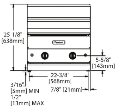
text_image
25-1/8" [638mm] 3/16" [5mm] MIN 1/2" [13mm] MAX 22-3/8" [568mm] 7/8" [21mm] 5-5/8" [143mm]Modèles GF-BRL
text_image
2" [53mm] 15-7/8" [404mm] 3" [77mm] 22-1/8" [562mm] 31-1/8" [91mm] 14-3/4" [375mm] 3-5/8" [94mm] CONNEXION ARRIÈRE DU GAZtext_image
LARGEUR 20-5/16" [516mm] PIED MAX 19-7/16" [504mm] PIED MIN 20" [508mm] ROULETTES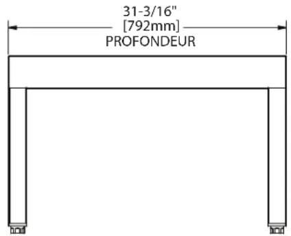
text_image
31-3/16" [792mm] PROFONDEURG24-BRL-STD
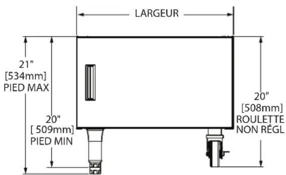
text_image
LARGEUR 21" [534mm] PIED MAX 20" [509mm] PIED MIN 20" [508mm] ROULETTE NON RÉGL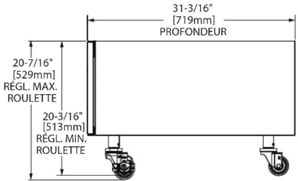
text_image
31-3/16" [719mm] PROFONDEUR 20-7/16" [529mm] RÉGL. MAX. ROULETTE 20-3/16" [513mm] RÉGL. MIN. ROULETTEG24-BRL-CAB
natural_image
Pure electrical circuit lines without any symbolsVentilation
natural_image
Two identical stainless steel electric cookers with heat sinks and control knobs (no visible text or labels)Incluye Los Modelos: G18-BRL, G24-BRL, G30-BRL, G36-BRL, G48-BRL, GF18-BRL, GF24-BRL, GF30-BRL Y GF36-BRL
PARA SU SEGURIDAD:
NO ALMACENE O UTILICE GASOLINA U OTROS VAPORES O LÍQUIDOS INFLAMABLES EN LAS CERCANÍAS DE ESTE O CUALQUIER OTRO ARTEFACTO.
ADVERTENCIA:
1177 Kamato Road, Mississauga, Ontario L4W 1X4
CANADA
Phone: 905-624-0260
Fax: 905-624-5669
General Inquires 1-905-624-0260
USA Sales 1-800-424-2411
Canadian Sales 1-888-442-7526
Canada or USA Parts/Service 1-844-724-2273
text_image
2-1/8" [53mm] 15-7/8" [404mm] 3" [77mm] 22-1/8" [562mm] 31-1/8" [709mm] 14-3/4" [375mm] 4" [100mm] CONEXIÓN POSTERIOR PARA GAS 3/4-14 NPTtext_image
1-3/8" [45mm] A* CONEXIÓN POSTERIOR PARA GAS 34-1/2" [876mm] 24-1/4" [617mm] 5" [127mm] 5-7/8" [149mm] ANCHO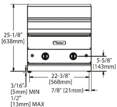
text_image
25-1/8" [638mm] 3/16" [5mm] MIN 1/2" [13mm] MAX 22-3/8" [568mm] 7/8" [21mm] 5-5/8" [143mm]Modelos GF-BRL
text_image
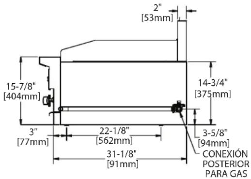
2" [53mm] 15-7/8" [404mm] 3" [77mm] 22-1/8" [562mm] 31-1/8" [91mm] 14-3/4" [375mm] 3-5/8" [94mm] CONEXIÓN POSTERIOR PARA GAStext_image
ANCHO 20-5/16" [516mm] PATA MÁX. 19-7/16" [504mm] PATA MÍN. 20" [508mm] RUEDAS LOCAS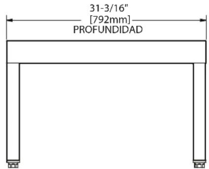
text_image
31-3/16" [792mm] PROFUNDIDADG24-BRL-STD
text_image
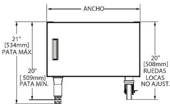
ANCHO 21" [534mm] PATA MÁX 20" [509mm] PATA MÍN. 20" [508mm] RUEDAS LOCAS NO AJUST.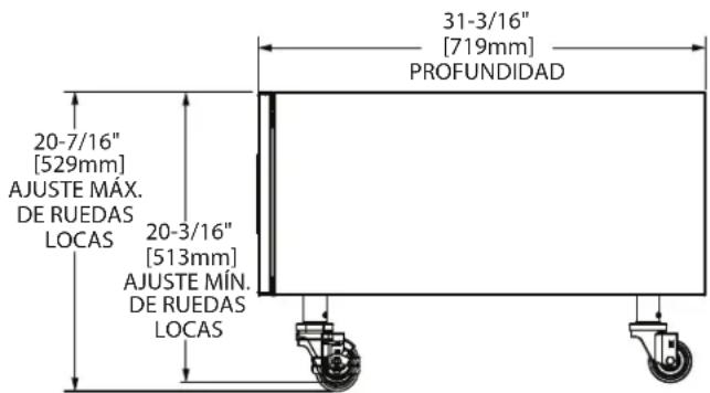
text_image
20-7/16" [529mm] AJUSTE MÁX. DE RUEDAS LOCAS 20-3/16" [513mm] AJUSTE MÍN. DE RUEDAS LOCAS 31-3/16" [719mm] PROFUNDIDADG24-BRL-CAB
GARLAND strongly recommends this unit be inspected for possible freight damage while carrier driver is on site.