
UC2024X - Ice Maker Scotsman - Free user manual and instructions
Find the device manual for free UC2024X Scotsman in PDF.


User questions about UC2024X Scotsman
0 question about this device. Answer the ones you know or ask your own.
Ask a new question about this device
Download the instructions for your Ice Maker in PDF format for free! Find your manual UC2024X - Scotsman and take your electronic device back in hand. On this page are published all the documents necessary for the use of your device. UC2024X by Scotsman.
USER MANUAL UC2024X Scotsman
natural_image
Line drawing of a mechanical device with four legs and a curved top panel (no text or symbols)Safety Information
Important Safety Information. Make sure to read through fully to avoid severe injury or death.

WARNING
R290 Refrigerant is
Flammable.
Flame can cause burns or property damage
Keep away from sources of fire
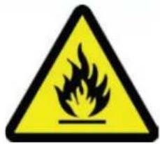
text_image
Warning sign depicting a flame symbol in yellow and black on a triangle
This ice machine contains FLAMMABLE refrigerant and improper use can result in fire or explosion. Do not use cigarettes, vapes, or cellphones near pipes or cables, as it can be a source of ignition or spark.

This ice machine must not be installed next to equipment with an open ignition source (ie. open flames, an operating gas appliance, or electric heater). Do not store explosive substances such as aerosol cans with a flammable propellant in this appliance.

WARNING: Do not use electrical appliances inside the food/ice storage compartments unless they are of the type recommended by the manufacturer.

WARNING: In order to reduce flammability hazards the installation of this appliance must only be carried out by a suitably qualified person.

This appliance must be installed according to the safety standard for refrigeration systems presented in ANSI/ASHRAE 15.

Do not install next to anything that continuously vibrates, avoiding excessive vibrations or pulsations.

Install in a well ventilated environment and ensure ventilation and outlets are not obstructed.

Properly secure electrical wiring and cabling for the machine to minimize wear, vibrations, corrosion, excessive pressure, sharp edges, or other adverse environmental effects that could cause damage to wiring over time.

Keep fire extinguisher nearby in case of emergencies.

WARNING: Do not damage the refrigerating circuit

Use a Scotsman recommended technician certified to repair R290 equipment.

Install ONLY Scotsman factory service parts. Use of non-OEM parts can be dangerous due to the design changes needed to safely use R290 refrigerant.

WARNING: Cancer and Reproductive Harm. Visit www.P65Warnings.ca.gov for details.

This appliance is not intended for use by persons (including children) with reduced physical, sensory or mental capabilities, or lack of experience and knowledge, unless they have been given supervision or instruction concerning the use of the appliance by a person responsible for their safety.

Children should be supervised to ensure that they do not play with the appliance.

Caution: This equipment should only be used on ice bins without electrical components or bins designed to be used with flammable refrigerants.
Safety Information

WARNING: Do not use means to accelerate the defrosting process or to clean, other than those recommended by the manufacturer. The appliance shall be stored in a room without continuously operating ignition sources

Do not pierce or burn.

Be aware that refrigerants may not contain an odor.

All installation, service, maintenance and decommissioning to be carried out by technicians certified to handle FLAMMABLE REFRIGERANTS.

Install in a well-ventilated environment and ensure ventilation and outlets are not obstructed.

When breaking into the refrigerant circuit to make repairs – or for any other purpose – conventional procedures shall be used. However, for flammable refrigerants, it is important that best practice be followed, since flammability is a consideration. The following procedure shall be adhered to:
a) safely remove refrigerant following local and national regulations;
b) purge the circuit with inert gas;
c) evacuate;
d) purge with inert gas;
e) open the circuit by cutting or brazing.

The refrigerant charge shall be recovered into the correct recovery cylinders if venting is not allowed by local and national codes. For appliances containing flammable refrigerants, the system shall be purged with oxygen-free nitrogen to render the appliance safe for flammable refrigerants. This process might need to be repeated several times. Compressed air or oxygen shall not be used for purging refrigerant systems. For appliances containing flammable refrigerants, refrigerants purging shall be achieved by breaking the vacuum in the system with oxygen-free nitrogen and continuing to fill until the working pressure is achieved, then venting to atmosphere, and finally pulling down to a vacuum. This process shall be repeated until no refrigerant is within the system. When the final oxygen-free nitrogen charge is used, the system shall be vented down to atmospheric pressure to enable work to take place. Ensure that the outlet for the vacuum pump is not close to any potential ignition sources and that ventilation is available.

Ensure that the leak detection equipment being used is suitable for use with FLAMMABLE REFRIGERANT; i.e., non-sparking, adequately sealed or intrinsically safe.

WARNING: This appliance should be stored in a room without continuously operating open flames (for example an operating gas appliance) or other potential ignition sources (for example an operating electric heater, hot surfaces).
UC2024X and UC2724X User Manual
Introduction
To the owner or user: this manual is intended to provide you and the maintenance or service technician with the information needed to install, startup, clean, maintain and repair this product. Observe any caution or warning notices. They are important and provide notice of potential hazards. Keep this manual for future reference.
If additional technical information is needed, go to Scotsman's website, www.scotsman-ice.com.
Note: This is a commercial product. If service is needed on a unit in a residence, warranty may be limited. Use a commercial service company. Locate one from the Scotsman website: www.Scotsman-ice.com
Scotsman Ice Systems are designed and manufactured with the highest regard for safety and performance. They meet or exceed UL60335-2-89, verified by a nationally recognized safety authority such as UL or ETL.
Table of Contents
Specifications Page 2
Cabinet Drawing ...... Page 3
Plan and Front Views ...... Page 4
Side and Back Views ...... Page 5
Placement....Page 6
Installation - Plumbing....Page 7
Installation - Electrical ...... Page 8
Initial Start Up ...... Page 9
Use and Operation ...... Page 10
For The Technician: Ice Bridge Thickness Adjustment ..... Page 11
For The Technician: Indicator Light Reference ...... Page 12
Maintenance and Cleaning ...... Page 13
Condensers and Air Filter Cleaning.... Page 15
Help.... Page 16
Wiring Diagram UC2024X and UC2724X Page 17
Decommissioning ...... Page 18

WARNING

CAUTION
Observe the Caution and Warning notices. They are indicators of important safety information. Keep this manual for future reference.
Fill out the Warranty Registration by using the attached warranty and mailing it in, or scan the QR code to be taken to the Scotsman warranty website:
UC2024X and UC2724X User Manual
Specifications
This ice maker is designed to be installed indoors, in a controlled environment. Although it can operate in a wide range of air and water temperatures, it will provide the best performance if not subject to extremes.
Air Temperature Limitations
• Maximum: 100 °F or 38°C
• Minimum: 50 °F or 10°C
Water Temperature Limitations
• Maximum: 100 °F or 38°C
• Minimum: 40 °F or 4.4°C
Water Pressure, Potable
• Maximum: 80 PSI or 5.5 BAR
• Minimum: 20 PSI or 1.3 BAR
Water Pressure, Condenser inlet
• Maximum: 145 PSI or 10 BAR
- Minimum: 20 PSI or 1.3 BAR; can be as low as 5 PSI or 0.3 BAR if clean and supplied with 45^ F water.
Potable Water Inlet Flow Rate
• 1.25 GPM or 4.7 LPM
Water Cooled Condenser GPM
- 70 °F or 21°C water: .25 GPM or .95 LPM
- 50 °F or 10°C water: .11 GPM or .41 LPM
Voltage 115 volt models
• Maximum 126 VAC
• Minimum 104 VAC
Operating the machine outside of any of the above limitations is considered abuse and any resulting damage is not covered by warranty and could cause a complete loss of warranty coverage.
Warranty Information
The warranty statement for this product is provided separately from this manual. Refer to it for applicable coverage.
This is a commercial model, if installed in a residence some commercial service companies may not be able to service it on site.
In general, warranty covers defects in material or workmanship. It does not cover maintenance, corrections to installations, or situations when the machine is operated in circumstances that exceed the limitations printed above.
Product Information:
The UC is available in two cube sizes. The ice size cannot be changed significantly. The ice is stored in an insulated bin with ice level automatically maintained by the control system.
A back flow preventer may be required by local plumbing codes.
115 volt models include a 5.5 ft. power cord with NEMA 5-15P plug.
Air cooled models flows in the right front and out the left front and include a cleanable air filter.
Legs are provided, thread size is 5/8-11. Replacement leg kit number is KLP7.
Machine may be installed without legs.
For available options and kits, see sales literature.
| Model | Electrical (Volts/Hz/Phase) | Condenser | Cube Size | Maximum Fuse Size or Breaker (Amps) | Power Cord Termination | Refrigerant Charge (oz) (R290) |
| UC2024SAX-1A 115 | 5/60/1 Air Small 15 5-1 | 5P plug 5.25 | ||||
| UC2024MAX-1A 115 | 5/60/1 Air Medium 15 | 5-15P plug 5.25 | ||||
| UC2024SWX-1A 115 | 5/60/1 Water Small 15 | 5-15P plug 4.50 | ||||
| UC2024MWX- 1A 115 | 15/60/1 Water Medium | 15 5-15P plug 4.50 | ||||
| UC2724SAX-1A 115 | 5/60/1 Air Small 15 5-1 | 5P plug 4.75 | ||||
| UC2724MAX-1A 115 | 5/60/1 Air Medium 15 | 5-15P plug 4.75 | ||||
| UC2724SWX-1A 115 | 5/60/1 Water Small 15 | 5-15P plug 4.50 | ||||
| UC2724MWX-1A 115 | 5/60/1 Water Medium | 15 5-15P plug 4.50 |
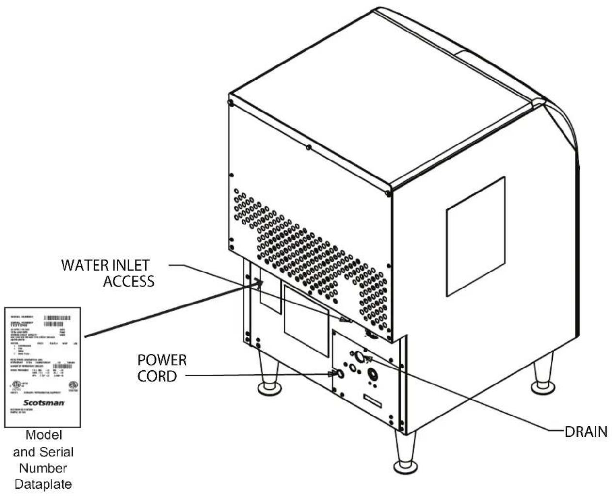
text_image
WATER INLET ACCESS POWER CORD DRAIN Model and Serial Number Dataplate Scotsman®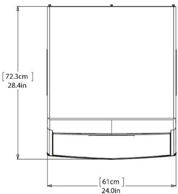
text_image
[72.3cm] 28.4in [61cm] 24.0in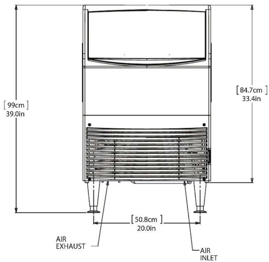
text_image
[99cm] 39.0in [84.7cm] 33.4in [50.8cm] 20.0in AIR EXHAUST AIR INLET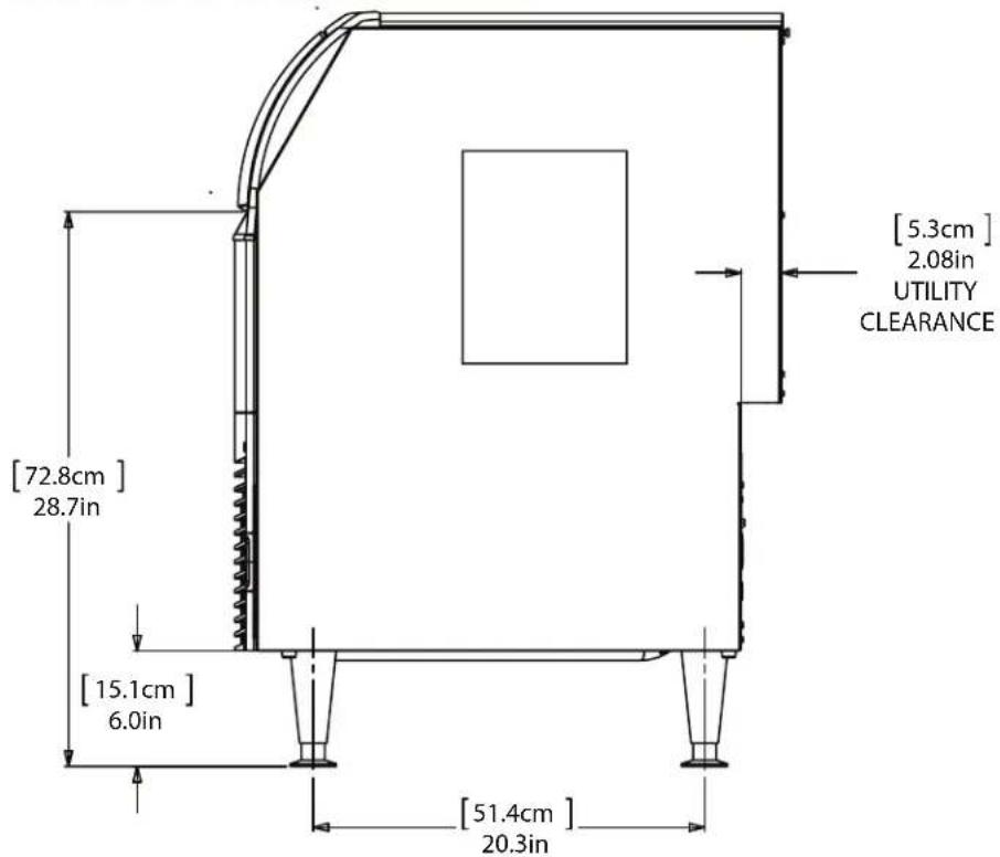
text_image
[72.8cm] 28.7in [15.1cm] 6.0in [51.4cm] 20.3in [5.3cm] 2.08in UTILITY CLEARANCE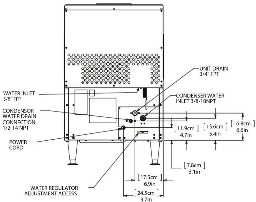
text_image
UNIT DRAIN 3/4" FPT WATER INLET 3/8" FPT CONDENSER WATER INLET 3/8-18NPT [11.9cm] [13.6cm] [16.8cm] POWER CORD [7.8cm] [17.5cm] [24.5cm] [3.1in] [4.7in] [5.4in] [6.6in] [9.7in] [17.5cm] [6.9in] WATER REGULATOR ADJUSTMENT ACCESSUC2024X and UC2724X User Manual
Placement
The location of the equipment should be selected with care. Consideration should be given to allow adequate space for air cooled models to breathe.
The ice machine is not designed for outdoor use. It must be installed indoors, in a controlled environment. The air and water temperatures must not exceed rated limits.
Scotsman assumes no liability or responsibility of any kind from products manufactured by Scotsman that have been altered in any way, including the use of any part and/or other components not specifically approved by Scotsman.
Scotsman reserves the right to make design changes and/or improvements at any time.
Specifications and design are subject to change without notice.
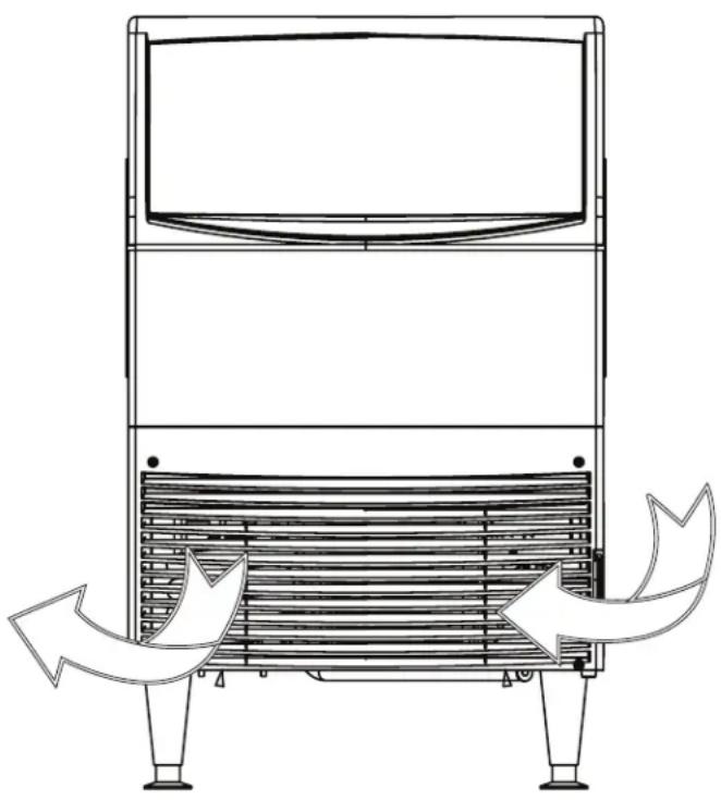
Airflow on air cooled models:
- Intake from the right grill
- Exhaust from the left grill
Do not install where this air flow is blocked.
natural_image
Technical line drawing of a mechanical device with internal structure and directional arrows indicating motion (no text or symbols)The power outlet must be located within the length of the supplied power cord. If legs will be used, allow space for the total cabinet height.
Air cooled models in a small room will require ventilation to exhaust heat from the condenser. The condenser fan and motor will generate some noise while the machine is running. Noise sensitive areas should consider water cooled equipment or locate the machine where the noise from ice making will not objectionable.
Unpack
- Separate the carton from the shipping pallet
- Inspect for any hidden shipping damage. If any is found, retain carton and notify carrier for potential claim. Shipping damage is not covered by warranty.

CAUTION
Tip Over hazard.
To prevent injury or damage to the machine please use caution when lifting the unit.
- Remove bolts holding machine to pallet.
- Install the legs. The legs are to be screwed into the same holes the shipping bolts were removed.
- Remove the protective plastic covering the panels. The longer it is left on the panel, the more difficult it will be to remove it.
Spacing:
No additional spacing is required at the top or sides. However, suggested minimum side clearance for the installation is 1/8" or 3.2 mm and suggested minimum top clearance is 1/4" or 6.4 mm.
The machine may be installed with 0 clearance at the back. Do not block louvers at the front of the cabinet.
Pre Installation:
Water supplied to the ice machine should be filtered. Install a filter system that filters out suspended solids. It may be necessary to add a coarse pre-filter ahead of the fine filter.
Inspect the place where the ice machine is to be installed. Check for:
• Space for the cabinet
- Water Supply
- Drain Availability
• Electrical Power Supply
UC2024X and UC2724X User Manual
Installation - Plumbing
Note: The building drain inlet must be lower than the drain outlets at the back of the ice machine.
The water supply must have a hand shut off valve accessible when the unit is installed.
For the Plumber
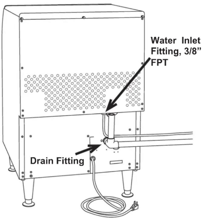
- Connect cold potable water to the 3/8" FPT inlet water fitting, located below the upper back panel. A water filter is recommended. Flush the water line prior to connecting to the ice machine.
A loop of copper tubing may be used between the ice machine and the water supply. This will allow the ice machine to be pulled out from its installed location without disconnecting water. No back flow preventer is required in the potable water line. This is provided by the sump inlet, which is above the sump water level which then cannot be siphoned.
-
Connect a drain tube to the drain fitting. Drain tubes for a water cooled machine should be run separately. The bin drain fitting is 3/4" FPT. And it is plastic. Do not overheat.
-
Drain tube material must be rigid and meet local code.
- Traps in the bin drain line without vents ahead of them will cause poor draining
-
The bin drain must be vented if there is a long horizontal run 5 feet or more. All drains are gravity and must have a minimum fall of 1/4" per foot of horizontal run.
-
Maintain the air gap required by local code between the end of the drain to, and the building drain receptacle.
- Drain tubing should be insulated to prevent condensation from forming on the tubing.
- Water cooled models have a separate 3/8" FPT fitting for condenser water inlet. DO NOT FILTER water to this connection. The condenser drain is 1/2" FPT and does not need a vent.
Water Cooled and Recirculating Systems Note
Water cooled equipment may be connected to a closed loop recirculating system. See the pressure limits on page 2.
The included water regulating valve will vary the amount of coolant needed to maintain a constant discharge pressure. Higher coolant temperatures will result in increased coolant flow to maintain the discharge pressure set point.
text_image
Water Inlet Fitting, 3/8" FPT Drain FittingUC2024X and UC2724X User Manual
Installation - Electrical
For the Electrician
This is a cord-connected unit and must be on a separate single phase power supply. Check the name plate for the correct voltage. Check the dataplate for the voltage, ampacity and maximum fuse size and per the dataplate use fuses or HACR circuit breakers. The maximum fuse size for this circuit should be 15 A, per the nameplate use fuses or HACR circuit breaker.
This ice machine should be installed on a dedicated circuit with a properly sized HACR-rated breaker or fuse. No other devices or appliances should be connected to the same circuit with the ice machine. Installing a unit on a shared circuit can cause product malfunctions or damage to the unit. The proper circuit size can be found on the unit data tag listed as "MAX FUSE OR HACR TYPE CIRCUIT BREAKER". Never allow the fuse size to exceed the maximum fuse size listed on the data tag.
The use of a ground fault circuit interrupter (GFCI) or arc-fault circuit interrupter (ARCI) can lead to nuisance trips and is not recommended for use on most appliances including our equipment.
If local codes or other specifications require the use of ground fault circuit interrupters, a properly rated HACR GFCI or ARCI circuit breaker should be used. An outlet type GFCI or ARCI is not recommended for ice machines and other refrigeration equipment due to more frequent nuisance trips of the GFCI or ARCI.
Always check with your local electrical inspector about the specific code requirements in your area for GFCI or ARCI breakers and GFCI or ARCI receptacles.
Follow All Local Codes - This Unit Must Be Grounded. Do not use extension cords and do not disable or by-pass ground prong on electrical plug.
Note: Electrical outlets can become worn and the connection can then be erratic. Have it replaced if it is loose.
After utility connections
- Level the cabinet, use the leg levelers on the end of the legs to adjust to cabinet height. Legs should have been installed when the unit was unpacked.
- Wash the bin and hood. If desired, the interior of the bin could be sanitized.
- Locate the scoop, wash it and have it available for use when needed.
UC2024X and UC2724X User Manual
Initial Start Up
Final check list:
| Ice machine is installed indoors with air and water temperature controlled within the limitations detailed in this manual | |
| Ice machine is level in its final position | |
| Electrical disconnect (switch or plug as required) is within sight of the installed machine | |
| Electrical circuit is dedicated to this ice maker | |
| Voltage has been confirmed within the specifications in this manual and the name plate on the ice maker | |
| Plumbing connections are complete and tested for leaks | |
| Ice maker is installed with proper clearance, allowing for service and utility connections | |
| Water shut off valve installed near the ice maker | |
| All packing material has been removed. |
Start up:
- Remove louvered front panel.
- Open the water valve to allow water to the unit. Check for leaks, if any found correct them.
- Switch electrical supply on.
- Move the On/Wash/Off rocker switch to On.
The machine will start the ice making process. The Anti-Slush light will be on, and after a 90 second delay, water will flow into the sump. The unit starts in a 90 second harvest or defrost mode before switching to the freeze mode.
Air cooled models will discharge warm air out the left side of the front panel. Water cooled models will discharge warm (about 120^ F/ 48^ C) water out of the condenser drain.
Freezing will continue until ice has formed adequately, then the system will switch to a harvest mode and the ice will release as a group, falling past the ice sensing plate and into the bin. When ice moves the ice sensing plate, that triggers the end of the harvest cycle.
- Move the On/Wash/Off switch to the off position to switch the machine off. Scoop out any ice in the bin.
- Create a solution of sanitizer. Mix 4oz/118ml of locally approved sanitizer and 2.5gal/9.5L of (90°F/32°C to 110°F/43°C) potable water to create a 200 ppm solution.
- Sanitize bin by wiping all surface areas with the sanitizer solution. Allow to air dry.
- Move the On/Wash/Off switch to ON.
- Replace louvered panel.
- Give the owner/user this manual, instruct him/her in the operation and maintenance requirements of the unit. Make sure they know who to call for service.
Fill out the Customer Evaluation and Warranty Registration form, and mail it in to Scotsman or register the unit at Scotsman's website (www.scotsman-ice.com).
Once started, the ice machine will automatically make ice until the ice piles up onto the ice sensing plate, holding it open. The typical ice level when the machine is off will be several inches below the door. When ice level drops from use or meltage, the ice machine will resume making ice.
Tip: To maximize ice storage, scoop the ice to the sides and front of the bin.
Noise:
This is a commercial ice machine. It contains a powerful compressor, and, if air cooled, a fan motor. It will produce some noise when it is making ice. Every effort was made during its design to minimize the sound level but some is unavoidable.
Typical Cycle Times (minutes)
Note: First cycle after any restart will be longer than listed here.
| 70/50°F. (21/10°C.) 90/70 °F. (32/21°C.) | ||||
| Freeze Harvest Freeze Harvest | ||||
| UC2024X | 16 1 20 1 | |||
| UC2724X | 14 1 15 1 | |||
The time to fill a warm storage bin from empty varies by cabinet temperature and cycle time, but will take about 8 hours.
UC2024X and UC2724X User Manual
Use and Operation
To use, simply lift the door by its bottom edge and slide it up and into the top of the machine. Use the scoop to remove ice and close the door.
Air cooled models must be able to take in room air and discharge air heated by the ice making process. They will make the most ice if there is plenty of room to breathe.
Blockage of vents or exposure to excessive heat will reduce the ice making and storage capacity.
The storage bin is insulated but not refrigerated, so ice will melt during use. That is normal and assures that fresh ice is available in the bin.
On air cooled models the fan will make some noise during operation, however rattles and other vibrations are not normal and should be attended to.
It is normal for the water to occasionally stop flowing over the evaporator (ice making surface) for a few seconds.
If the machine is in a space colder than the minimums listed it can become damaged.

WARNING
Risk of Personal Injury
The cabinet is not designed to support anything placed on it. Do NOT step or stand on it.
This appliance is not intended for use by persons (including children) with reduced physical, sensory or mental capabilities, or lack of experience and knowledge, unless they have been given supervision or instruction concerning use of the appliance by a person responsible for their safety.
Children should be supervised to ensure that they do not play with the appliance.

CAUTION
The ice making surface can be damaged by abrasion or by sharp objects. Do NOT scrub the ice making surface with anything.
UC2024X and UC2724X User Manual
For The Technician: Ice Bridge Thickness Adjustment
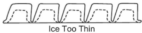
Note: The bridge thickness adjustment is used to obtain the CORRECT size, not to adjust to individual preferences. Do NOT make the ice bridge too thick or too thin, as either will reduce ice making capacity. Do NOT attempt to adjust the machine to release individual cubes. There is only ONE correct size.
Refer to the Ice Thickness Diagram for proper ice size.
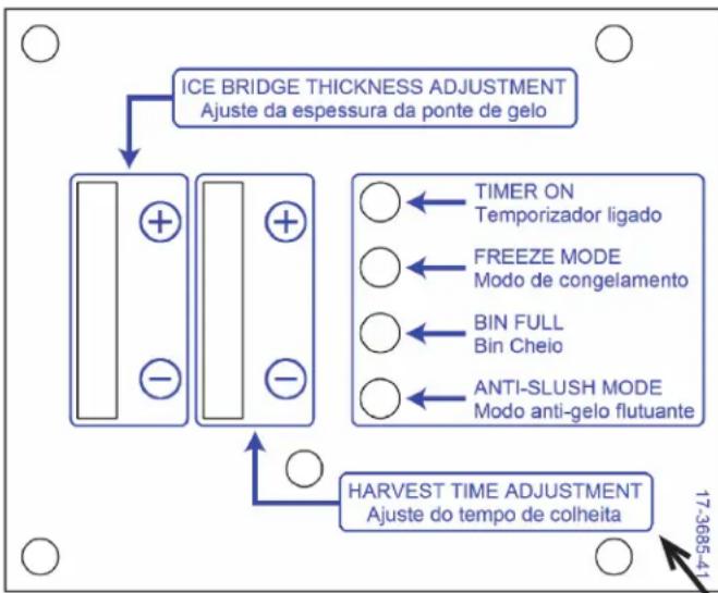
Access the controller by removing the front panel and pulling out the electrical panel drawer.
Adjust by pushing the + sign or – sign on the ice bridge adjustment section of the control panel. Changing bridge thickness should be a one-time adjustment as the machine will automatically maintain that ice thickness.
natural_image
Black-and-white illustration of a hand with a lightning bolt and smoke trail (no text or symbols)WARNING
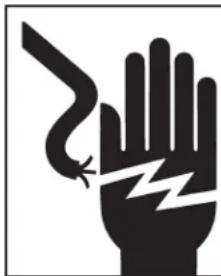
Electrical Shock Hazard Disconnect electrical power before beginning
flowchart
graph TD
    A["ICE BRIDGE THICKNESS ADJUSTMENT\nAjuste da espessura da ponte de gelo"] --> B["Block 1"]
    A --> C["Block 2"]
    B --> D["TIMER ON\nTemporizador ligado"]
    B --> E["FREEZE MODE\nModo de congelamento"]
    B --> F["BIN FULL\nBin Cheio"]
    B --> G["ANTI-SLUSH MODE\nModo anti-gelo flutuante"]
    C --> H["HARVEST TIME ADJUSTMENT\nAjuste do tempo de colheita"]
    H --> I["17-3685-4"]
Ice Thickness Diagram
text_image
Ice Too Thin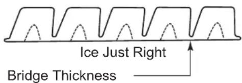
text_image
Ice Just Right Bridge Thickness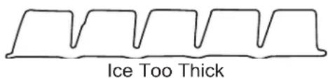
text_image
Ice Too ThickController Diagram: Adjustment Indicator Lights
Each push and release of the + or - button will change the lights that glow or blink indicating a change in ice size.
Example: pushing + one time changes a blinking light to steady on type. If the lights are on steady a single push of + will add one more light to the right and it will blink.
There are 10 settings. All 5 lights on steady is the maximum setting and one blinking light is the minimum.
This Section Not Used
UC2024X and UC2724X User Manual
For The Technician: Indicator Light Reference
There are four indicator lights visible when the electrical component drawer is pulled out.
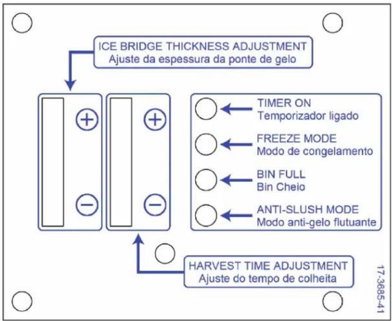
flowchart
graph TD
    A["ICE BRIDGE THICKNESS ADJUSTMENT\nAjuste da espessura da ponte de gelo"] --> B["Block 1"]
    A --> C["Block 2"]
    B --> D["Timer ON\nTemporizador ligado"]
    B --> E["FREEZE MODE\nModo de congelamento"]
    B --> F["BIN FULL\nBin Cheio"]
    B --> G["ANTI-SLUSH MODE\nModo anti-gelo flutuante"]
    C --> H["HARVEST TIME ADJUSTMENT\nAjuste do tempo de colheita"]
Timer Cut In
- This light is switched ON when the freeze cycle has progressed significantly enough for the evaporator thermostat to have reached its freeze preset temperature. At this point there are only a few minutes left in the freeze cycle. It is also switched ON when the harvest cycle has been on and the evaporator thermostat has reached its set defrost temperature.
Curtain Switch
- Normally OFF. This light is switched on and off by the position of the ice sensing plate.
Freeze Cycle.
- Normally ON during a freeze cycle. OFF during harvest or ice release.
Anti Slush
- Normally OFF. This light is switched ON when the pump is stopped during a freeze cycle.
A typical cycle begins when there is no ice on the ice sensing plate (Curtain Switch light OFF). The compressor and water pump will switch ON and when the discharge pressure increases to the cut in point of the fan pressure switch the fan motor will begin to rotate the fan. The hot gas and inlet water solenoids are off.
This continues until the evaporator temperature sensor reaches a preset point, which causes the pump to stop for a few seconds (the Anti Slush light will switch ON). After the Anti Slush light goes out and the water pump is switched back on, the freeze cycle continues until the evaporator temperature sensor reaches the timer start point, (Timer Cut In light is switched on).
When the timer has reached the end of its preset freeze time, Harvest begins (the Freeze Cycle light is switched off). The water pump stops, the hot gas valve and inlet water solenoid valve open and the discharge pressure falls, so the fan motor stops. Harvest continues until the released ice causes the ice sensing plate to move and the Curtain Switch light will either: a) blink On and Off, if the ice bin is not full, or b) switch On when the bin is full and ice is on the ice sensing plate.
If the bin is full the machine will shut off and be in a stand by mode. If not full, the cycle will repeat.
UC2024X and UC2724X User Manual
Maintenance and Cleaning
Frequency: Cleaning is recommended about twice a year. The ice machine will not maintain a sanitary condition without human intervention.
Prep: Obtain food grade scale remover such as Scotsman Clear 1. You will also need a clean container, sanitizer, clean cloths and clean rubber gloves. Use of a spray bottle is recommended for ease of washing hard to reach areas.
Note: The ice machine must be connected to water, power and drain during this procedure.
- Remove the front panel and move the on/off/wash switch to Off.
- Remove the ice from the ice storage bin.
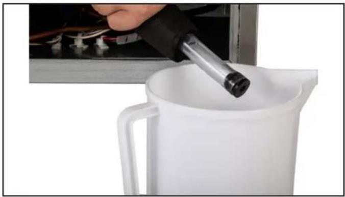
- Drain the sump water into the container by removing the plug from the drain hose. The drain hose is under the control box area. Return the plug to the drain hose.
text_image
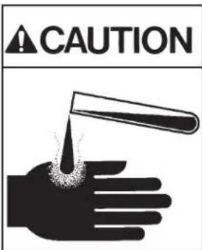
CAUTIONIce machine scale remover contains acids. Acids can cause burns.
If concentrated cleaner comes in contact with skin, flush with water. If swallowed, do NOT induce vomiting. Give large amounts of water or milk. Call Physician immediately. Keep out of the reach of children.
natural_image
Close-up of a hand pouring liquid into a white pitcher with a black tool, no visible text or symbols- Put the rubber gloves on.
- Mix a solution of scale remover and potable water.
Mix a solution of 5 oz or 150 cc of Scotsman Clear 1 Scale Remover and
2.5 quarts or 2.4 liters of clean, warm (95°F/35°C to 115°F./46°C) potable water.
-
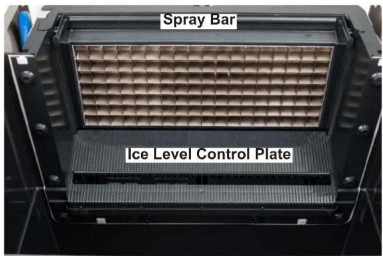
Remove the spray bar by unsnapping it from the left and right ends.
-
Remove the ice level control plate by unsnapping it.
-
Place both into the scale remover. Wash them with the clean cloths.
-
Install both the spray bar and ice level control plate back onto the ice machine.
-
Pour the scale remover into the machine's sump.
-
Put the machine into a wash mode. Operate it that way for 20 minutes.
-
Stop the wash mode.
text_image
Spray Bar Ice Level Control PlateUC2024X and UC2724X User Manual
- Drain the scale remover solution by removing the plug from the drain hose. Return the plug to the drain hose.
- Check that the scale has cleared from the spray bar. Remove spray bar if needed to clear any scale, be sure it is returned to its original position.
- Mix a second solution of scale remover and lukewarm potable water.
- Wash the interior of the ice storage bin with the scale remover solution.
- Pour any remaining scale remover solution into the bin. Be sure it drains away.
- Mix a solution of sanitizer and lukewarm potable water: Mix 4 oz/118ml of locally approved sanitizer and 2.5 gal/9.5L of (90°F/32°C to 110°F/43°C) potable water to create a 200 ppm solution.
- Pour half of the solution into the sump.
- Switch the control into a wash mode. Operate it that way for 10 minutes and then switch it to off.
- Drain the sump by removing the drain plug from the drain hose. Return the drain plug to the drain hose.
- Wash all interior surfaces of the ice storage bin, including bin door, with the remaining sanitizer solution.
- Pour a gallon of hot potable water into the bin to clean out the drain.
- Switch the control to ice making and return the front panel to the unit.
UC2024X and UC2724X User Manual
Condensers and Air Filter Cleaning
Filters and Air Cooled Condenser
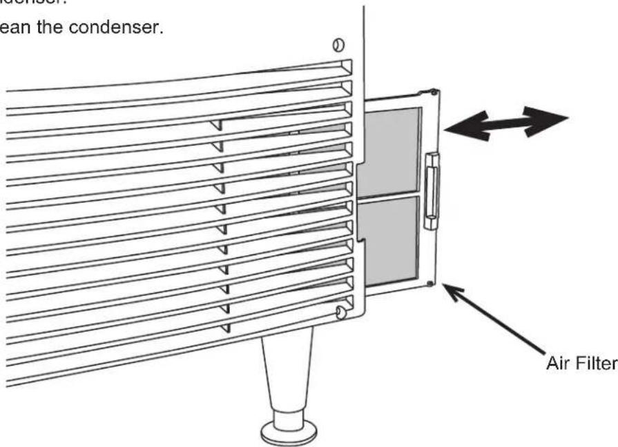
The air filter located on the lower front grill will capture airborne dust during operation. As the dirt builds up, it begins to restrict air flow and causes the refrigeration system to work less efficiently. Clean the air filter regularly.
Remove the filter by sliding it to the right until it is clear of the ice machine.
Note: It is a snap fit and the snaps may be very tight. Pull hard with two thumbs.
Remove dust and dirt by washing the filter in a utility sink.
Reinstall filter in the ice machine.
text_image
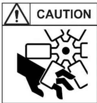
CAUTIONRotating fan blade can cause personal injury.
Unplug unit from power supply before beginning to clean condenser
Water cooled equipment may be connected to a closed loop recirculating system or to a regular water supply. See the pressure limits on page 2.
The included water regulating valve will vary the amount of water or coolant needed to maintain a constant discharge pressure. Higher coolant temperatures will result in increased coolant flow to maintain the discharge pressure set point.
That pressure is factory set to 135 PSIG. If needed, it may be field adjusted to that set point. An access port to the adjustment stem is available on the lower back panel.
In areas with highly mineralized water, the inside of the condenser may become coated with scale. When that occurs the amount of water used by the condenser will increase, as the water regulating valve opens further to keep the discharge pressure at the set point.
Scale on the inside of the condenser may be cleaned by circulating an acid solution with an auxiliary pump.
Condenser
The condenser fins require semi annual cleaning. Use caution to prevent damage to the condenser fins.
Lightly brush dust from the condenser.
Use a vacuum to thoroughly clean the condenser.
text_image
clean the condenser. Air FilterRemove and Clean the Air Filter
August 2025
UC2024X and UC2724X User Manual
Help
Before calling for service, check here for your issue.
Problem: No ice, the machine is silent.
- Be sure the unit is plugged in and that there is power at that outlet. You might temporarily plug the unit into another, nearby outlet to confirm.
- Be sure the ice level sensor plate is in the make ice position.
- If water cooled, is there water pressure to the unit? If the water has been turned off, the machine might shut itself off to keep from damaging its refrigeration system. It will automatically restart after water has been restored and several minutes have passed.
- Remove the front panel and check that the On/Off switch is in the On position.
Problem: No ice, the machine is appears to be operating.
- Check that there is water to the machine. Air cooled models will continue to operate without water but no ice will be made.
- Check for air flowing in and out off air cooled models. If none, call for service.
Problem: Ice is either too thick or too thin.
- The ice size may need to be adjusted by a technician. Call for service.
- The ice size sensor may have failed. Call for service.
Winterizing
To prepare a unit for storage, follow these suggestions:
- Clean the unit per the instructions in this manual or those on the unit.
- Discard all ice.
- Drain the unit of all water.
- Disconnect the water supply tubing from the unit.
- Unplug the power cord from the outlet.
- Wipe the cabinet clean.
- Cover the machine to keep dust off the cabinet.
text_image
POWER IN * SEE NAMEPLATE FOR PROPER VOLTAGE REQUIREMENTS AND MAXIMUM FUSE SIZE EARTH GROUND V W LINE TRANSFORMER L2/N L1 TERMINAL BOARD T1 BK/W BK/W BK W W Bk COIL POWER RELAY CON NO BK ON 6 ON 3 2 4 WASH 3-WAY SWITCH OFF BN/W BV/W FUSE (2A) TYPE AGC FAST ACTING MATER TEMP SENSOR EVAPIDATOR TEMP SENSOR CLRTAIN SWITCH 12V 12V GND COMPRESSOR NO FREEZE NO HARVEST NO PUMP CON PUMP NC WATER INLET NO R Y BU WATER SOLENOOD PUMP MOTOR W R/W FUSE (2A) TYPE AGC FAST ACTING HOT GAS SOLENOOD FAN CONTROL (AC ONLY) BN FAN MOTOR (AC ONLY)Shown in ice making mode
UC2024X and UC2724X User Manual
Decommissioning
Only qualified technicians familiar with R290 refrigerant should decommission a machine, as special tools and containers are required for the removal, transportation, and disposal of this highly flammable substance.
Work shall be undertaken under a controlled procedure so as to minimise the risk of a flammable gas or vapour being present while the work is being performed.
• Before attempting the procedure:
- All maintenance staff and others working in the local area shall be instructed on the nature of work being carried out. Work in confined spaces shall be avoided.
- The area shall be checked with an appropriate refrigerant detector prior to and during work, to ensure the technician is aware of potentially toxic or flammable atmospheres. Ensure that the leak detection equipment being used is suitable for use with all applicable refrigerants, i.e., nonsparking, adequately sealed, or intrinsically safe.
- If any hot work is to be conducted on the refrigerating equipment or any associated parts, appropriate fire extinguishing equipment shall be available on hand. A dry chemical or CO2 fire extinguisher should be adjacent to the charging area.
-
No person carrying out work in relation to a REFRIGERATING SYSTEM which involves exposing any pipe work shall use any sources of ignition in such a manner that it may lead to the risk of fire or explosion. All possible ignition sources, including cigarette smoking, should be kept sufficiently far away from the site of installation, repairing, removing and disposal, during which refrigerant can possibly be released to the surrounding space. Prior to work taking place, the area around the equipment shall be surveyed to make sure that there are no flammable hazards or ignition risks. “No Smoking” signs shall be displayed.
-
Ensure that all protective gear is present and used throughout the procedure.
- Make sure recovery equipment and containers are available and ready for use. All containers used for recovery must be rated for R290 refrigerant and must be labeled as such.
-
Weigh any refrigerant prior to reclaiming.
-
Maintain safety through standard operating procedures as outlined on page 20 of this document. Be sure to follow local, state, and federal guidelines for proper disposal.
- Do not fill containers more than 80% and do not exceed the pressure limits of the container. Make sure the machine to be decommissioned is in satisfactory working order and that the electrical components of the machine are properly sealed to prevent ignition.
- Recovered refrigerant should not be charged into another refrigerating system or mixed in another container.
- Make sure to safely transport the refrigerant in line with standard operating procedures.
- All recovered refrigerant must be returned to refrigerant supplier for proper disposal.
- If compressor or compressor oils are removed ensure it has been removed to an acceptable level so the flammable refrigerant does not remain in the lubricant.
- In addition to conventional charging procedures, the following requirements shall be followed:
- Ensure that contamination of different refrigerants does not occur when using charging equipment. Hoses or lines shall be as short as possible to minimise the amount of refrigerant contained in them.
- Cylinders shall be kept in an appropriate position according to the Instructions.
UC2024X and UC2724X User Manual
Decommissioning
- Ensure that the REFRIGERATING SYSTEM is earthed prior to charging the system with refrigerant.
- Label the system when charging is complete (if not already).
- Extreme care shall be taken not to overfill the REFRIGERATING SYSTEM.
- Prior to recharging the system, it shall be pressure-tested with the appropriate purging gas. The system shall be leak-tested on completion of charging but prior to commissioning. A follow up leak test shall be carried out prior to leaving the site
- Before carrying out this decommissioning procedure, it is essential that the technician is completely familiar with the equipment and all its detail. It is recommended good practice that all refrigerants are recovered safely. Prior to the task being carried out, an oil and refrigerant sample shall be taken in case analysis is required prior to re-use of recovered refrigerant. It is essential that electrical power is available before the task is commenced.
- Become familiar with the equipment and its operation.
• Isolate the system electrically.
- Before attempting the procedure, ensure that:
- mechanical handling equipment is available, if required, for handling refrigerant cylinders;
- all personal protective equipment is available and being used correctly;
- the recovery process is supervised at all times by a competent person;
• recovery equipment and cylinders conform to the appropriate standards.
- Pump down refrigerant system, if possible.
- If a vacuum is not possible, make a manifold so that refrigerant can be removed from various parts of the system.
- Make sure that cylinder is situated on the scales before recovery takes place.
- Start the recovery machine and operate in accordance with instructions.
- Do not overfill cylinders (no more than 80 % volume liquid charge).
- Do not exceed the maximum working pressure of the cylinder, even temporarily.
- When the cylinders have been filled correctly and the process completed, make sure that the cylinders and the equipment are removed from site promptly and all isolation valves on the equipment are closed off.
- Recovered refrigerant shall not be charged into another REFRIGERATING SYSTEM unless it has been cleaned and checked.
- Equipment shall be labelled stating that it has been de-commissioned and emptied of refrigerant. The label shall be dated and signed. For appliances containing FLAMMABLE REFRIGERANTS, ensure that there are labels on the equipment stating the equipment contains FLAMMABLE REFRIGERANT.
Decommissioning
- When removing refrigerant from a system, either for servicing or decommissioning, it is recommended good practice that all refrigerants are removed safely. When transferring refrigerant into cylinders, ensure that only appropriate refrigerant recovery cylinders are employed. Ensure that the correct number of cylinders for holding the total system charge is available. All cylinders to be used are designated for the recovered refrigerant and labelled for that refrigerant (i.e., special cylinders for the recovery of refrigerant). Cylinders shall be complete with pressure-relief valve and associated shut-off valves in good working order. Empty recovery cylinders are evacuated and, if possible, cooled before recovery occurs. The recovery equipment shall be in good working order with a set of instructions concerning the equipment that is at hand and shall be suitable for the recovery of all appropriate refrigerants including, when applicable, FLAMMABLE REFRIGERANTS. In addition, a set of calibrated weighing scales shall be available and in good working order.
- Hoses shall be complete with leak-free disconnect couplings and in good condition. Before using the recovery machine, check that it is in satisfactory working order, has been properly maintained and that any associated electrical components are sealed to prevent ignition in the event of a refrigerant release. Consult manufacturer if in doubt. The recovered refrigerant shall be returned to the refrigerant supplier in the correct recovery cylinder, and the relevant waste transfer note arranged. Do not mix refrigerants in recovery units and especially not in cylinders. If compressors or compressor oils are to be removed, ensure that they have been evacuated to an acceptable level to make certain that FLAMMABLE REFRIGERANT does not remain within the lubricant. The evacuation process shall be carried out prior to returning the compressor to the suppliers. Only electric heating to the compressor body shall be employed to accelerate this process. When oil is drained from a system, it shall be carried out safely.
Scotsman®
Ice Systems
natural_image
Line drawing of a stainless steel industrial machine with cooling fins and mounting feet (no text or symbols)
WARNING
text_image
Warning sign depicting a flame symbol in yellow and black on a white backgroundUC2024X and UC2724X User Manual

UC2024X and UC2724X User Manual

text_image
[72,3 cm] 28,4 po [61 cm] 24,0 po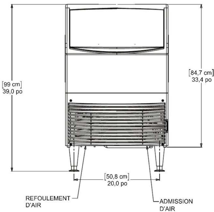
text_image
[99 cm] 39,0 po [84,7 cm] 33,4 po [50,8 cm] 20,0 po REFOULEMENT D'AIR ADMISSION D'AIRnatural_image
Technical line drawing of a mechanical device with internal structure and directional arrows indicating motion (no text or symbols)natural_image
Black silhouette of a hand with a lightning bolt and a broken rope symbol (no text or labels)AVERTISSEMENT
natural_image
Close-up of a hand pouring liquid into a white pitcher with a black tool, no visible text or symbolsUC2024X and UC2724X User Manual
101 Corporate Woods Parkway
Vernon Hills, IL 60061
800-726-8762
www.scotsman-ice.com