KD-TPQC-007-20x24ft - Garden shed Vevor - Free user manual and instructions
Find the device manual for free KD-TPQC-007-20x24ft Vevor in PDF.

| Brand | Vevor |
| Model | KD-TPQC-007-20x24ft |
| Product Type | Garden shed / Carport |
| Dimensions | 20 x 24 feet (6.1 x 7.3 m) |
| Main Material | Galvanized steel |
| Color | Not specified (gray or white depending on model) |
| Weight | Approximately 150 kg (estimate) |
| Maximum Load Capacity | Not specified, designed to shelter a vehicle |
| Intended Use | Car shelter, outdoor storage |
| Number of people needed for installation | At least 2 adults |
| Safety Precautions | Do not sit or stand on the roof; anchor firmly to the ground |
| Weather conditions for installation | Do not install in rainy, windy, or stormy weather |
| Anchoring required | Yes, provided by the user (cables, stakes) |
| Inspection before use | Check the condition of parts and fastening |
| Maintenance and cleaning | Clean with a damp cloth; check bolts regularly |
| Spare parts available | Yes, contact the manufacturer |
| Warranty | Not specified, generally 1 year |
| Repairability | Individually replaceable parts |
| User manual | Included, 160 pages in multiple languages |
Frequently Asked Questions - KD-TPQC-007-20x24ft Vevor
User questions about KD-TPQC-007-20x24ft Vevor
0 question about this device. Answer the ones you know or ask your own.
Ask a new question about this device
Download the instructions for your Garden shed in PDF format for free! Find your manual KD-TPQC-007-20x24ft - Vevor and take your electronic device back in hand. On this page are published all the documents necessary for the use of your device. KD-TPQC-007-20x24ft by Vevor.
USER MANUAL KD-TPQC-007-20x24ft Vevor
Affordable. Reliable. Home Improvement.
Heavy Duty carports
Model: KD-TPQC-007-20x24ft
Technical Support and E-Warranty Certificate
www.vevor.com/support
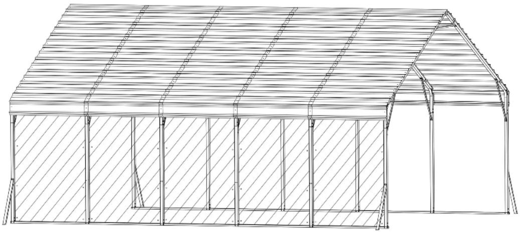
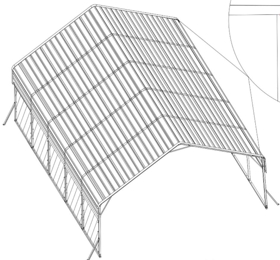
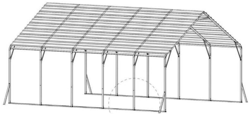
CARPORT INSTALLATION INSTRUCTION
Model: KD-TPQC-007-20x24ft
natural_image
Architectural line drawing of a two-story building with hatched walls and arched openings (no text or symbols)This is the original instruction, please read all manual instructions carefully before operating. VEVOR reserves a clear interpretation of our user manual. The appearance of the product shall be subject to the product you received. Please forgive us that we won't inform you again if there are any technology or software updates on our product.
IMPORTANT! PLEASE READ THIS INSTRUCTION CAREFULLY BEFORE INSTALLATION.
- Have at least two adults during installation. Readall instructions carefully and follow it accordingly. Failure to do so may result to injury or damage to the carport.
- Never set-up the product in rainy, windy or stormy conditions, especially lighting storms.
- Keep your carport off of thesteep sloppes and inclination.
- After installation, the carport should be anchored to prevent damage and possible injury. It is the user's responsibility to properly anchor the product.
- Aleays inspect the carport and each part before use. Make sure that everything istighely secured. Replace any worn, defective missing parts.
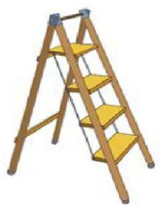
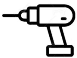
- For abetter installation and use experience, it is recommended to bring your own ladder, scissors, wlect-ic drill and glass glue.
SAFETY INSTRUCTIONS
WARNING:
Read this material before using this product. Failure to do so can result in serious injury.
Assembly precautions
- Assemble only according to these instructions. Improper assembly can create hazards.
- Wear ANSI-approved safety goggles and heavy-duty work gloves during assembly.
- Keep the assembly area clean and well-lit.
- Keep bystanders out of the area during assembly.
- Do not assemble if tired or when under the influence of alcohol, drugs or medication.
- The product capabilities apply to properly and completely assembled products only.
- Assemble on a flat, level, hard and smooth surface capable of safely supporting the Wooden Hall Tree.
- For additional information regarding the parts listed in the following pages, please refer to the Assembly Diagram of this manual. Unwrap and separate all parts in a clean work area.
Use precautions
- DO NOT SIT OR STAND ON THIS ITEM.
- This product is not a toy. Do not allow children to play with or near this item.
- Do not exceed specified weight capacities.
- Use only on a flat, level, hard, and smooth surface that can safely support a fully loaded Wooden Hall Tree.
- Use as intended only.
- Inspect before every use; do not use if parts are loose or damaged.
SAVE THIS MANUAL
IMPORTANT! PLEASE READ THIS INSTRUCTION CAREFULLY BEFORE INSTALLATION.
- Installation requires at least two adults. Read all instructions carefully and follow it accordingly. Failure to do so may result in injury or damage to the carport.
- Never set up the product in rainy, windy or stormy conditions, especially lighting storms.
- Keep your carport off of the steep slopes and inclination.
- After installation, the carport should be anchored to prevent damage and possible injury. It is the user's responsibility to properly anchor the product.
- Always inspect the carport and each part before use. Make sure that everything is tightly secured. Replace any worn, defective missing parts.
- For a better installation and use experience, it is recommended to bring your own ladder, scissors, electric drill and glass glue.
natural_image
Illustration of a wooden ladder with four yellow steps (no text or symbols)Ladder

natural_image
Line drawing of a pair of scissors (no text or symbols)Scissors
natural_image
Simple line drawing of a handheld electric drill (no text or symbols)Electric drill
PACKAGE CONTENTS
This carport is packed in 5 boxes. Before the installation, please check all the parts according to the part list. If there is any part missing or defective, please contact us immediately to get replacement parts.
| Part No. | Part Name | Drawing | Qty |
| #1 | Side pole 1 |  | 10PCS |
| #2 | Side pole 2 |  | 5 PCS |
| #3 | Straight peak pole | 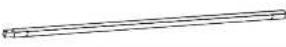 | 12 PCS |
| #4 | Leg pole | 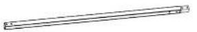 | 12 PCS |
| #5 | Top Reinforcing pole | 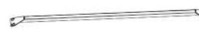 | 18 PCS |
| #6 | Ground bar 1 | 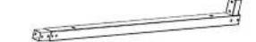 | 8 PCS |
| #6a | Ground bar 2 | 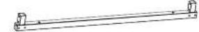 | 2 PCS |
| #7 | Connector | 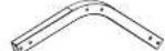 | 18 PCS |
| #8 | Ground Reinforcing pole | 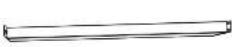 | 4 PCS |
| #9 | Side-side defense pole | 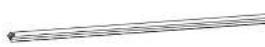 | 10 PCS |
| #10 | Side plate 1 |  | 3 PCS |
| #11 | Side plate 2 |  | 4 PCS |
| #R | Roof cover | 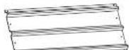 | 85 PCS |
| #G1 | M5X20 Self-Tapping screws | 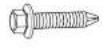 | 322PCS |
| #G1a | M5X25 Self-Tapping screws | 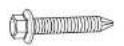 | 24 PCS |
| #G2 | Socket head bolt |  | 314 PCS |
| #G3 | Expansion screws | 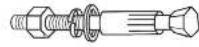 | 26 PCS |
| #G4 | Socket head bolt & Nut | 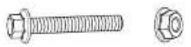 | 38 PCS |
| #L | Gloves |  | 2 pairs |
| #Y1 | Waterproof tape |  | 8 PCS |
| #Y2 | Anti-cut tape | 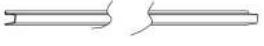 | 20 M |
| #Y3 | Enclosure |  | 5 PCS |
| #Y4 | Beads of rope |  | 60 PCS |
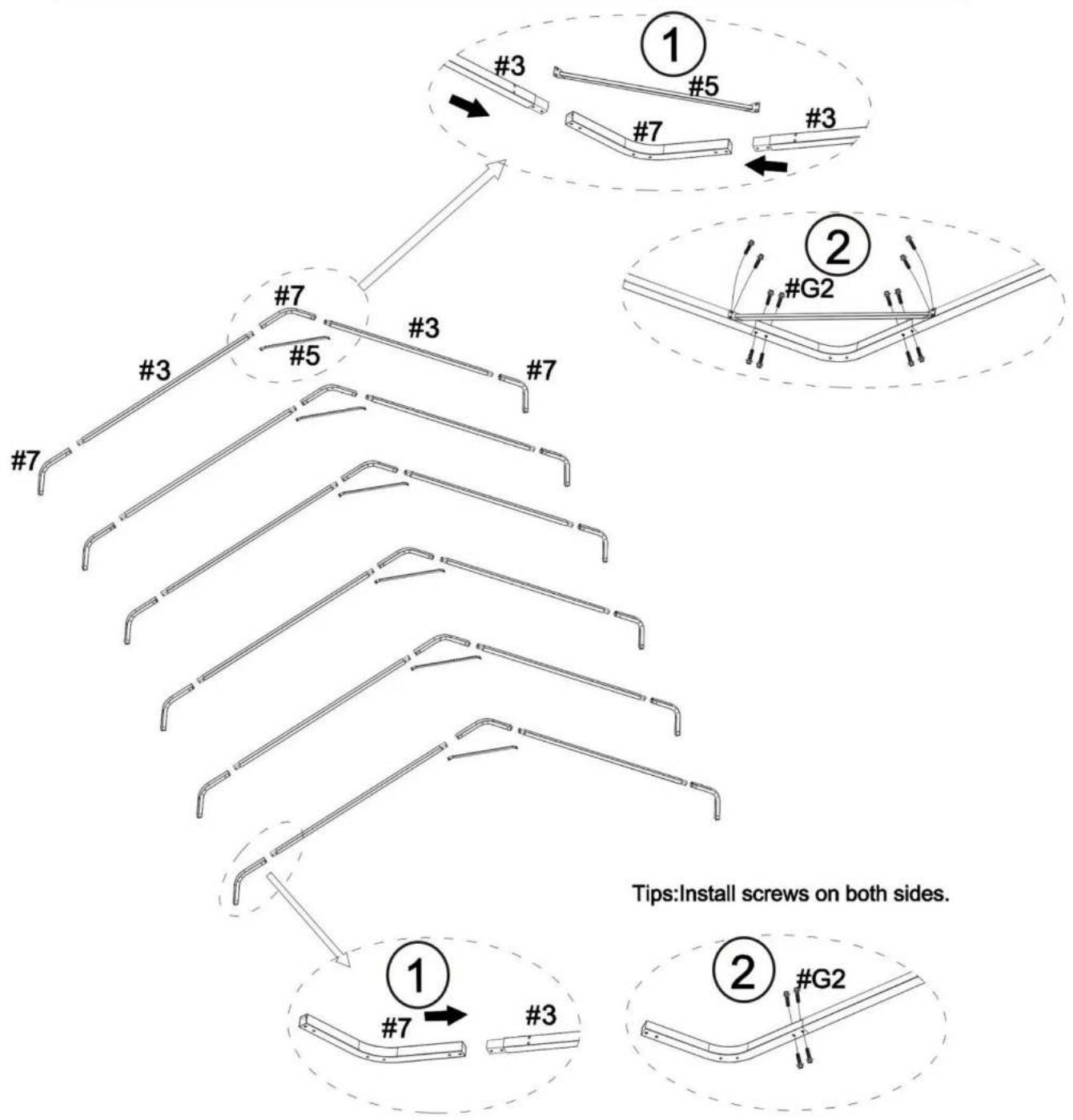
STEP 1: Assemble the Top Frame
| #3 | 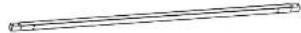 | X12 |
| #5 | 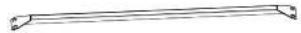 | X6 |
| #7 | 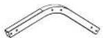 | X18 |
| #G2 | X120 |
Notice:
The linking screws in this step are all: Socket Head Bolt (#G2)

flowchart
graph TD
    A["#3"] --> B["#5"]
    B --> C["#7"]
    C --> D["#3"]
    D --> E["#7"]
    F["#2"] --> G["#G2"]
    G --> H["#3"]
    H --> I["#7"]
    style A fill:#f9f,stroke:#333
    style B fill:#f9f,stroke:#333
    style C fill:#f9f,stroke:#333
    style D fill:#f9f,stroke:#333
    style E fill:#f9f,stroke:#333
    style F fill:#f9f,stroke:#333
    style G fill:#f9f,stroke:#333
    style H fill:#f9f,stroke:#333
    style I fill:#f9f,stroke:#333
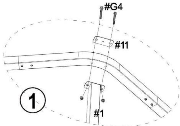
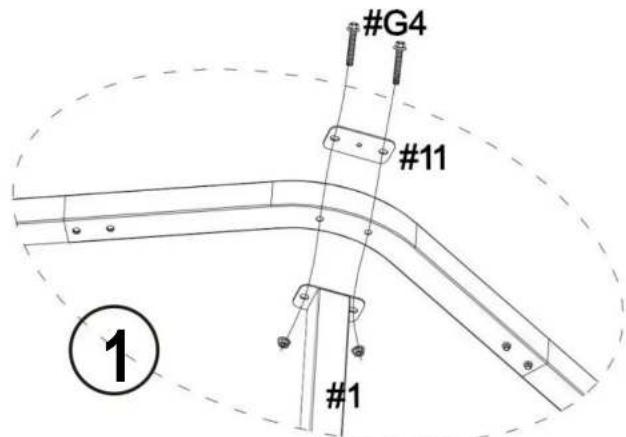
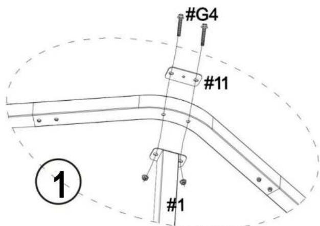
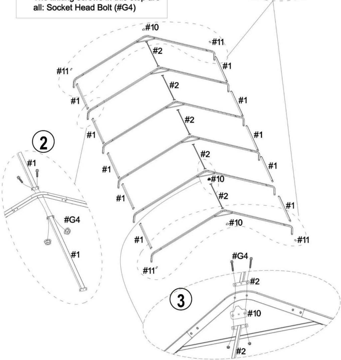
STEP 2:
| #1 | X10 | |
| #2 | X5 | |
| #10 | X3 | |
| #11 | X4 | |
| #G4 | 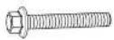 | X36 |
Notice:
The linking screws in this step are all: Socket Head Bolt (#G4)

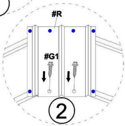
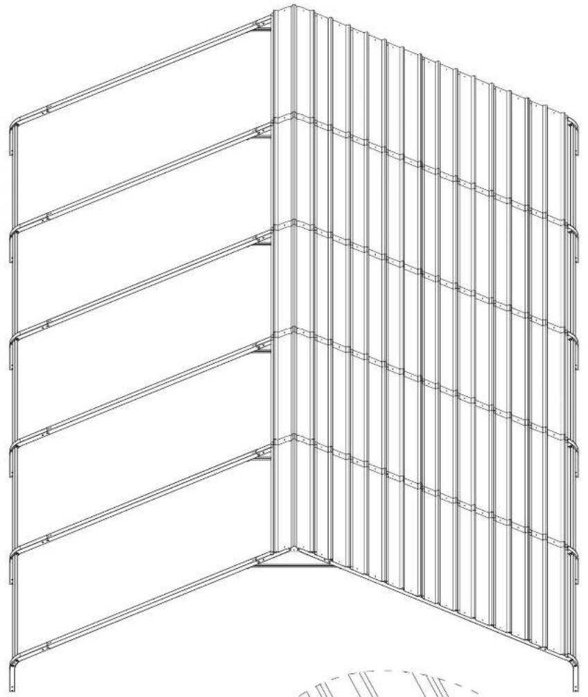
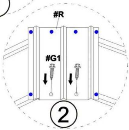
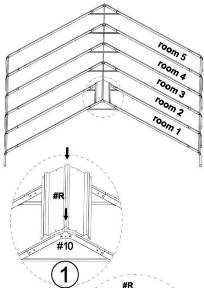
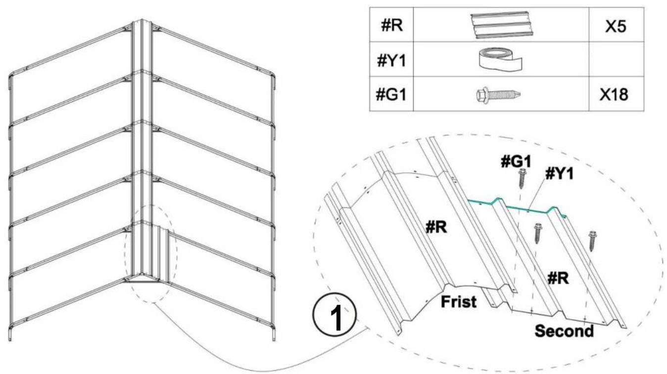
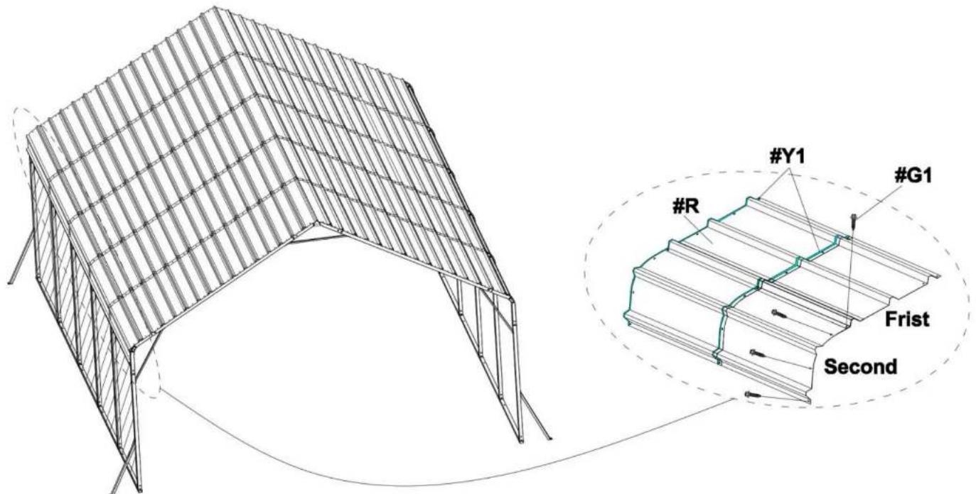
STEP 3: Install the Top Roof
Install all the Roof Cover (#R) to the top frame. The linking screws in this step are all:Self-Tapping Screws (#G1), as shown in the picture.
Notice:
- The meaning of different coloerd holes in the Roof Cover(#R);
● Blue hole:no screws here right now.
○ Black hole: nonal installation
1) Starting from the top middle of room 1 to room 5, install the first row of Roof Covers(#R).
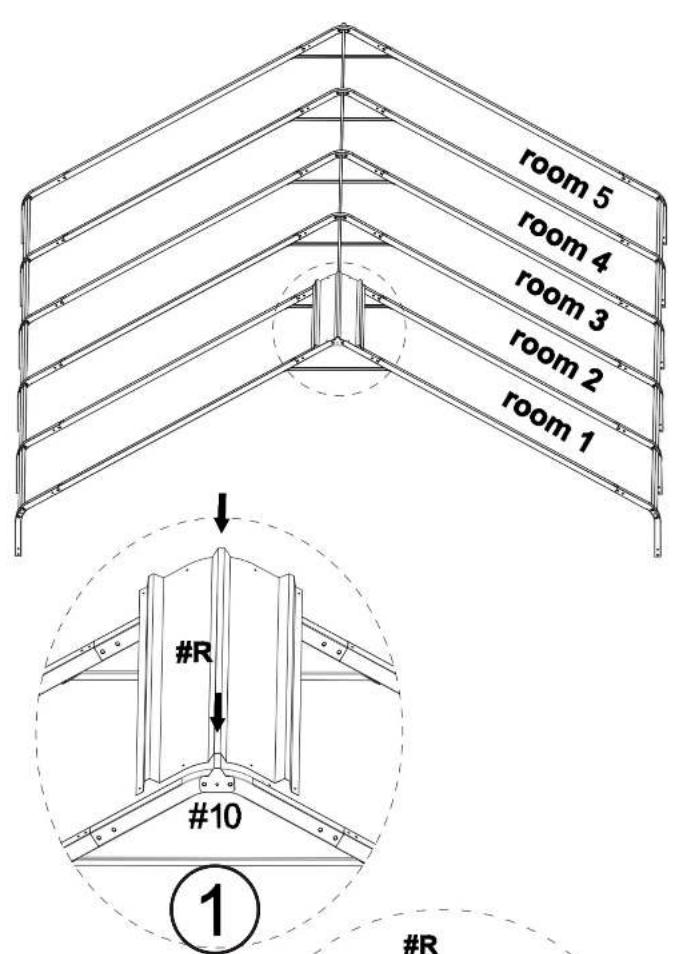
When installing the first piece of roof covering, place the middle slot of the tile at the gasket #10 bump for easy reinforcement with screws
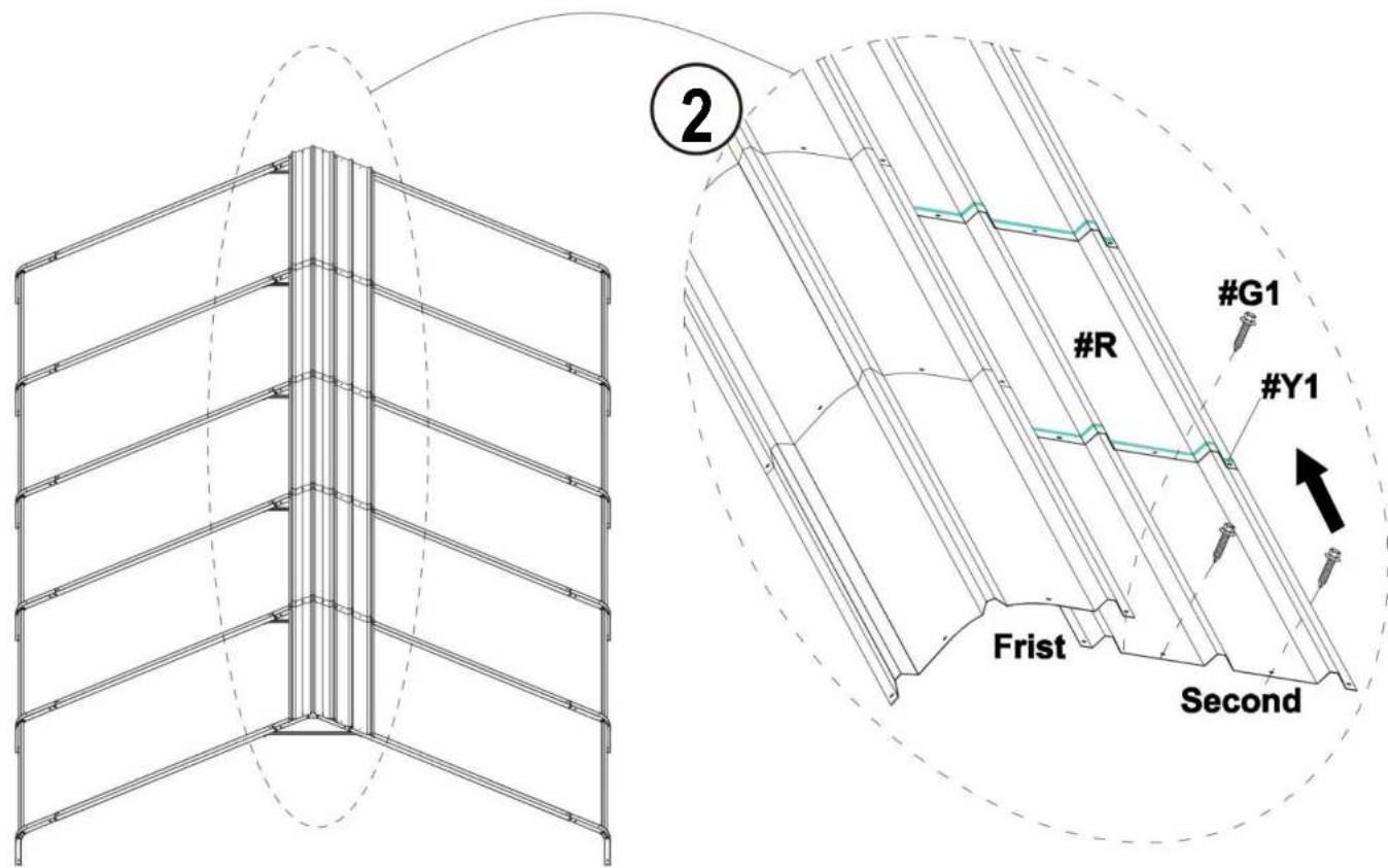
| #R |  | X1 |
| #Y1 |  | X8 |
| #G1 |  | X2 |
2) When installing each Roof Cover (#R), you need to use Waterproof Tape (#Y1) as shown in the picture.
natural_image
Technical line drawing of a multi-tiered structural frame structure (no text or symbols)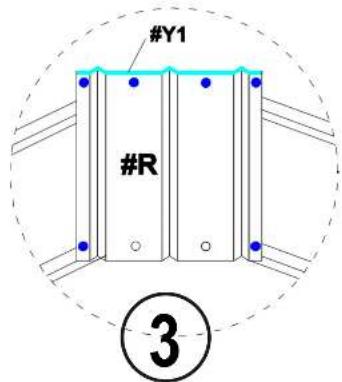
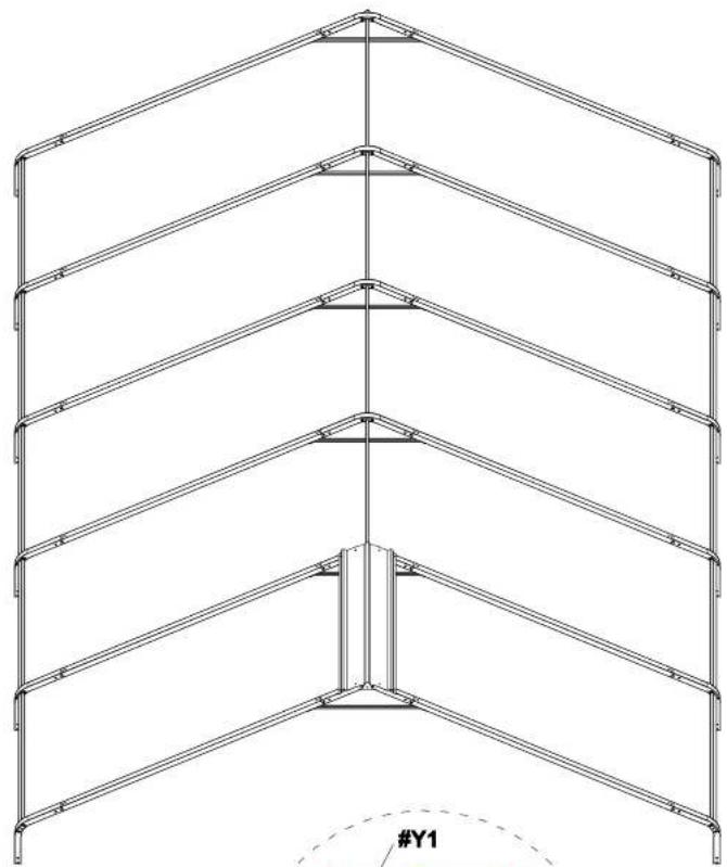
STEP 4:
Notice:
- Make sure that the screw holes are aligned, and then press the Waterproof Tape (#Y1)
- Make sure there are no gaps between the two roof covers to prevent water leakage
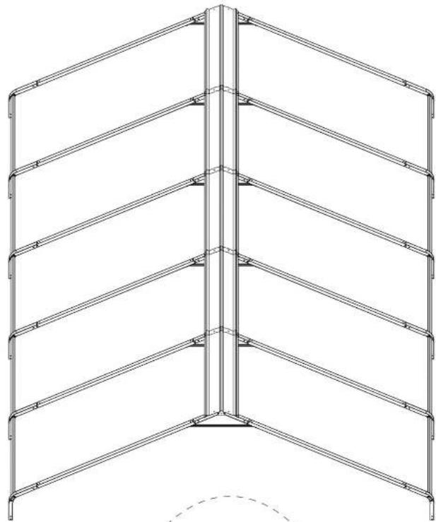
3.1) The second Roof Cover (#R) needs to be placed on the first Roof Cover (#R)
| #R | 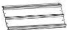 | X4 |
| #Y1 |  | |
| #G1 |  | X10 |
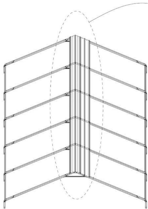
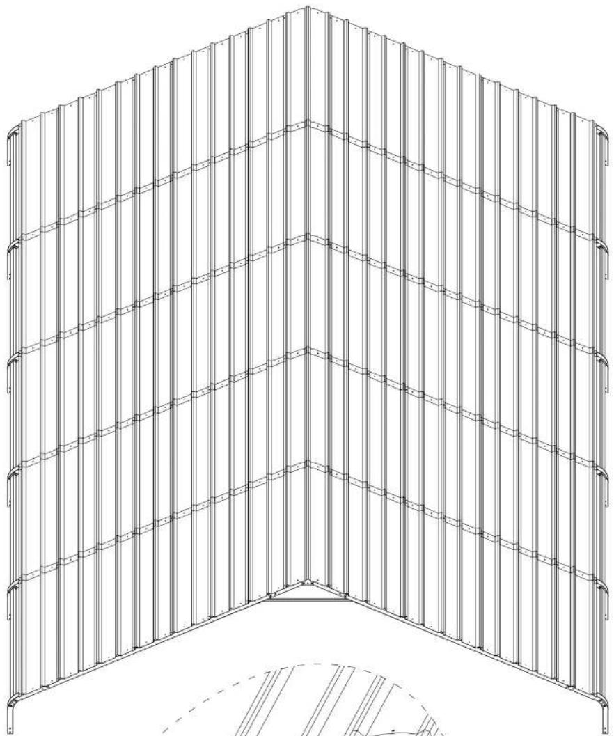
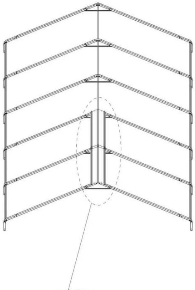
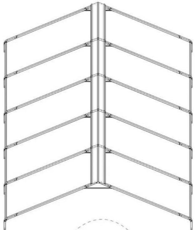
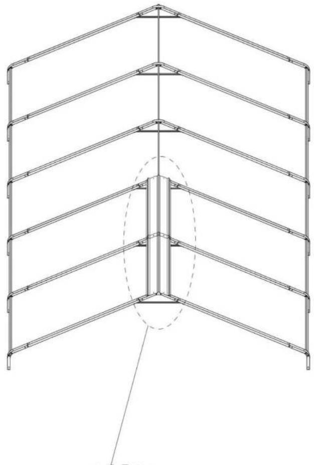
3.2) Follow the previous steps and continue to install the remaining Roof Cover (#R) in the middle row.
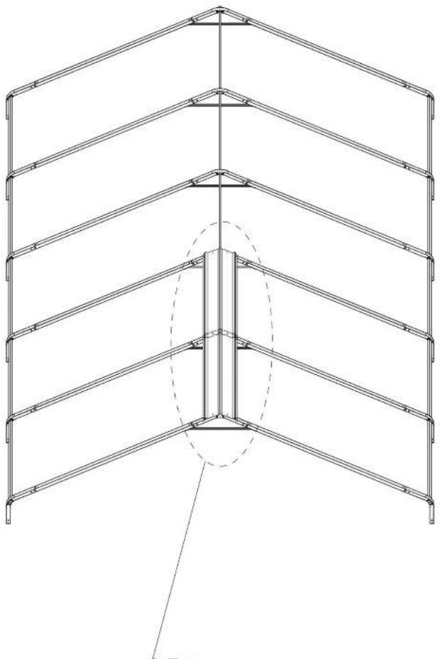
natural_image
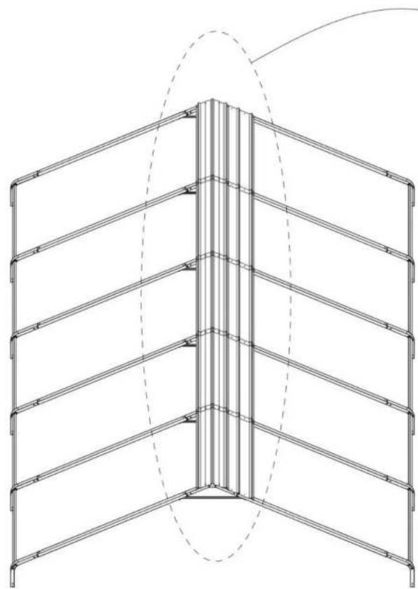
Technical line drawing of a multi-level structural frame with a central vertical component and dashed oval detail (no text or symbols)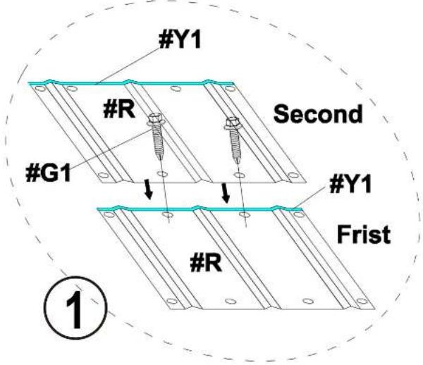
natural_image
Technical line drawing of a vertical structural frame with multiple horizontal beams and supports (no text or symbols)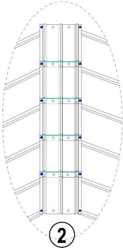
natural_image
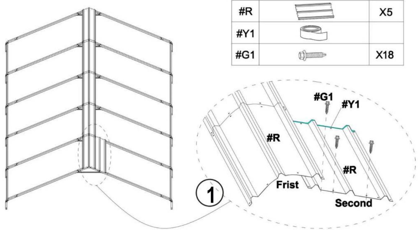
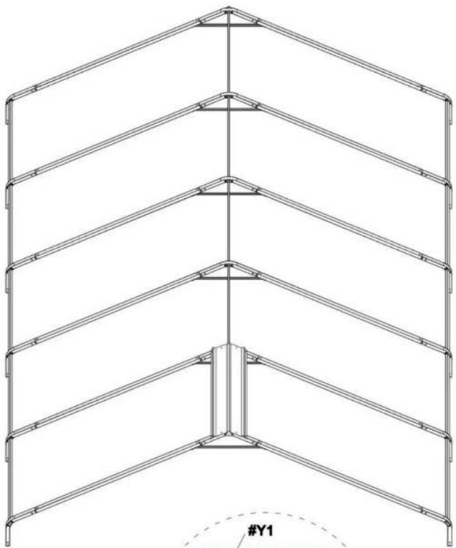
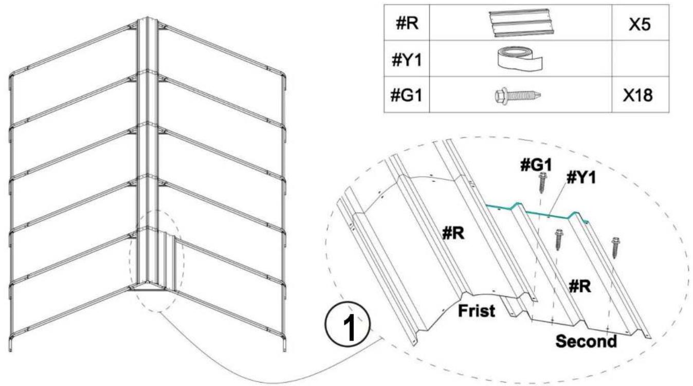
Structural diagram of a multi-story building frame with horizontal beams and vertical supports, enclosed in an oval boundary (no text or symbols)4.1) After installing the middle row, continue to install the 4 rows on the right. Each newly installed Roof Cover (#R) in a row needs to be placed below the Roof Cover (#R) in the previous row, as shown in the picture.

| #R | X5 | |
| #Y1 | ||
| #G1 | X18 |
4.2) Same as the previous step, after pasting the Waterproof Tape(#Y1) of RoofCovers(#R), install the next Roof Covers(#R).
natural_image
Technical line drawing of a structural frame with vertical supports and horizontal beams, no text or symbols present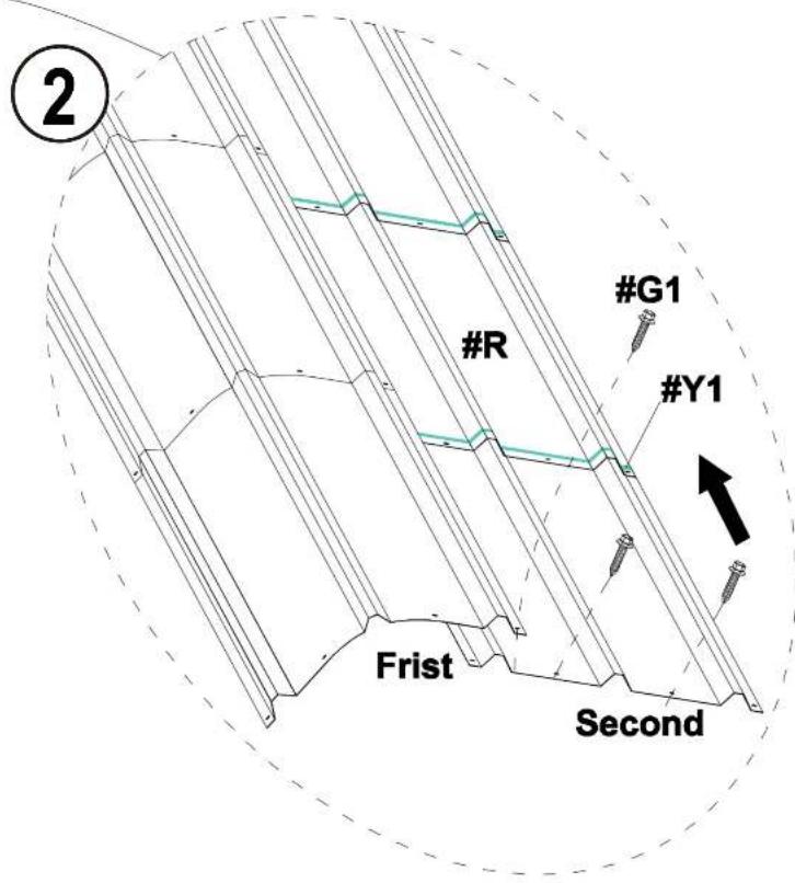
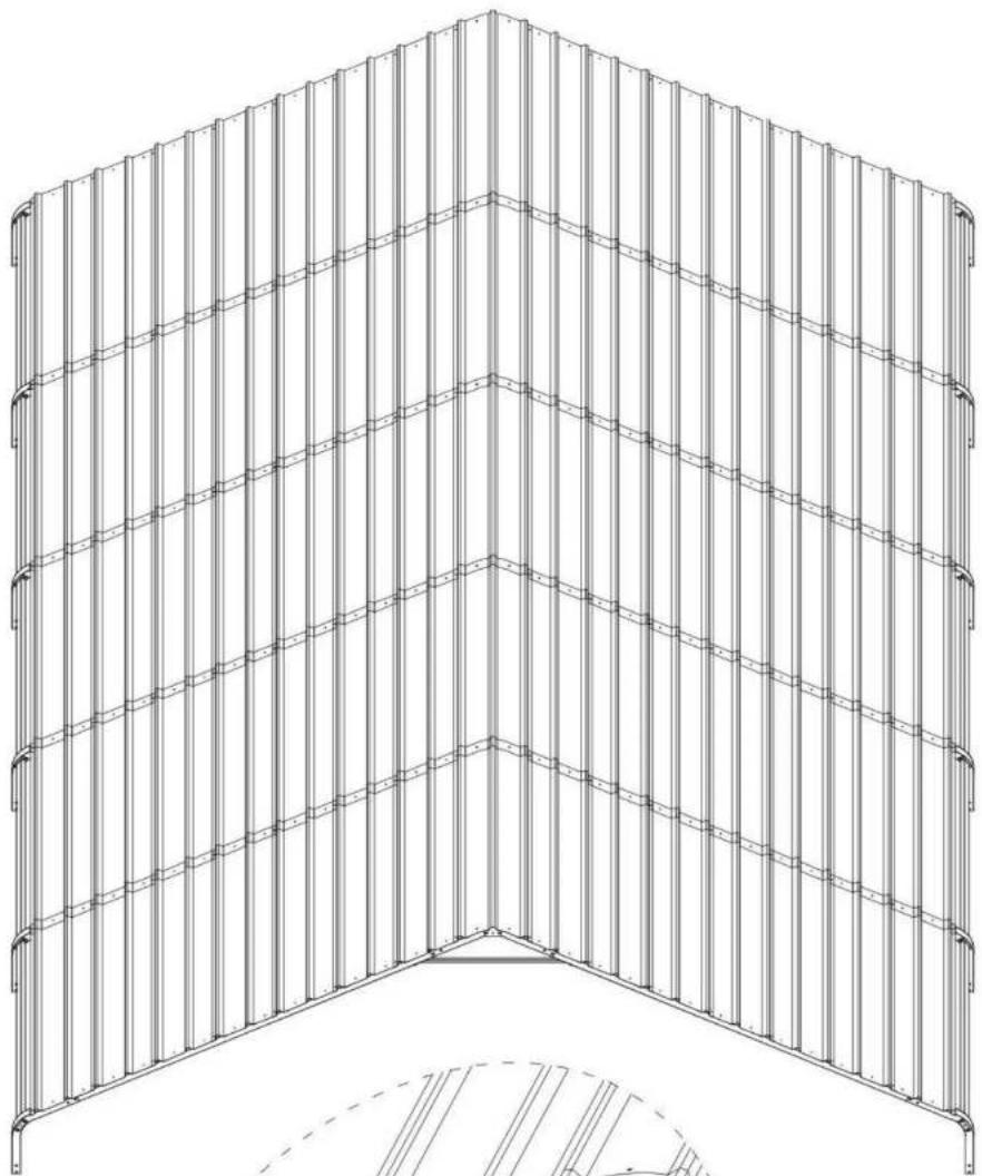
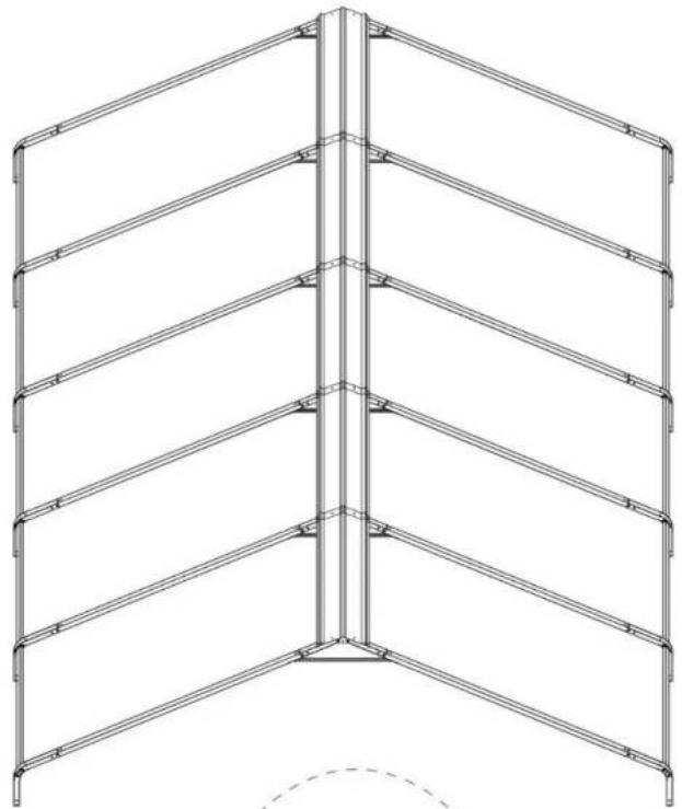
4.3) Follow the previous steps and continue to install the Roof Cover (#R) in the remaining 6 rows on the right.
| #R | X30 | |
| #Y1 | ||
| #G1 | X108 |
natural_image
Technical line drawing of a multi-tiered metal shelving unit (no text or symbols)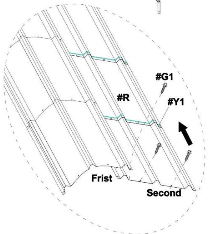
5.2) Same as the installation steps for the 6 rows on the right, please complete the installation of Roof Cover(#R) of the 7 rows on the left.
| #R | X35 | |
| #Y1 | ||
| #G1 | X126 |
natural_image
Architectural line drawing of a three-tiered structural framework with vertical supports (no text or symbols)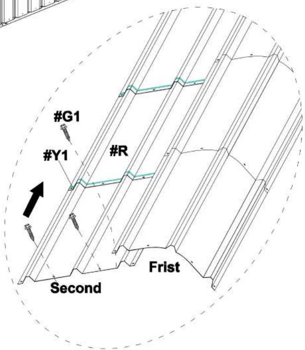
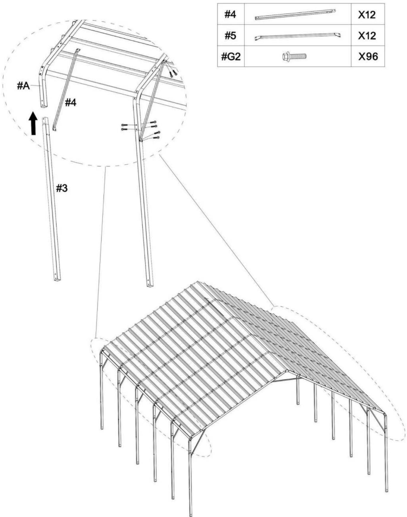
STEP 5: Connect Legs
1) Install Leg Pole(#4) and Top Reinforcing pole(#5) to the Connector(#7).
2) The linking screws in this step are all: Hex Head Cap Bolt (#G2).
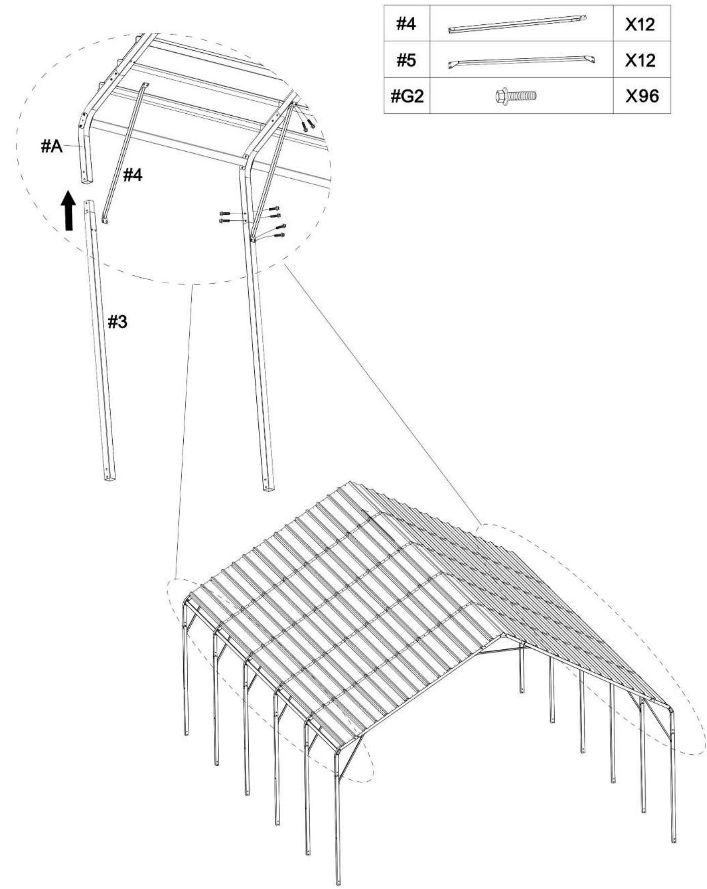
| #4 | X12 | |
| #5 | X12 | |
| #G2 | X96 |
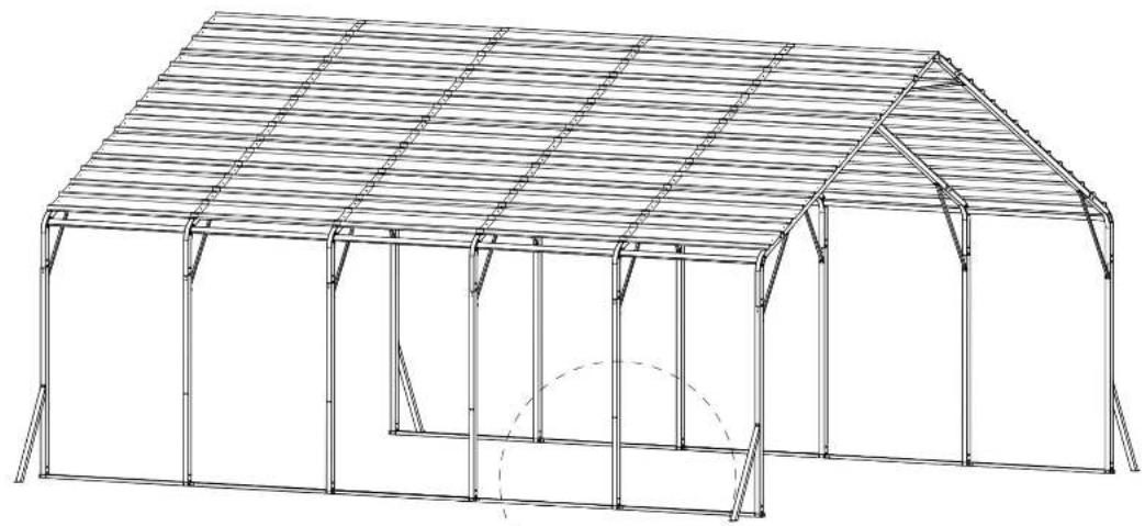
STEP 6: Reinforce the Frame
1) Connect all the Leg Pole(#4) to Ground bar 1(#6) and Ground bar 2(#6a) 2) The linking screws in this step are all: Hex Head Cap Bolt (#G2) and Expansion screws (#G3).
| #6 | X8 | |
| #6a | X2 | |
| #8 | X4 | |
| #G2 | X88 |
natural_image
Architectural line drawing of a large arched structure with vertical supports and horizontal beams (no text or symbols)
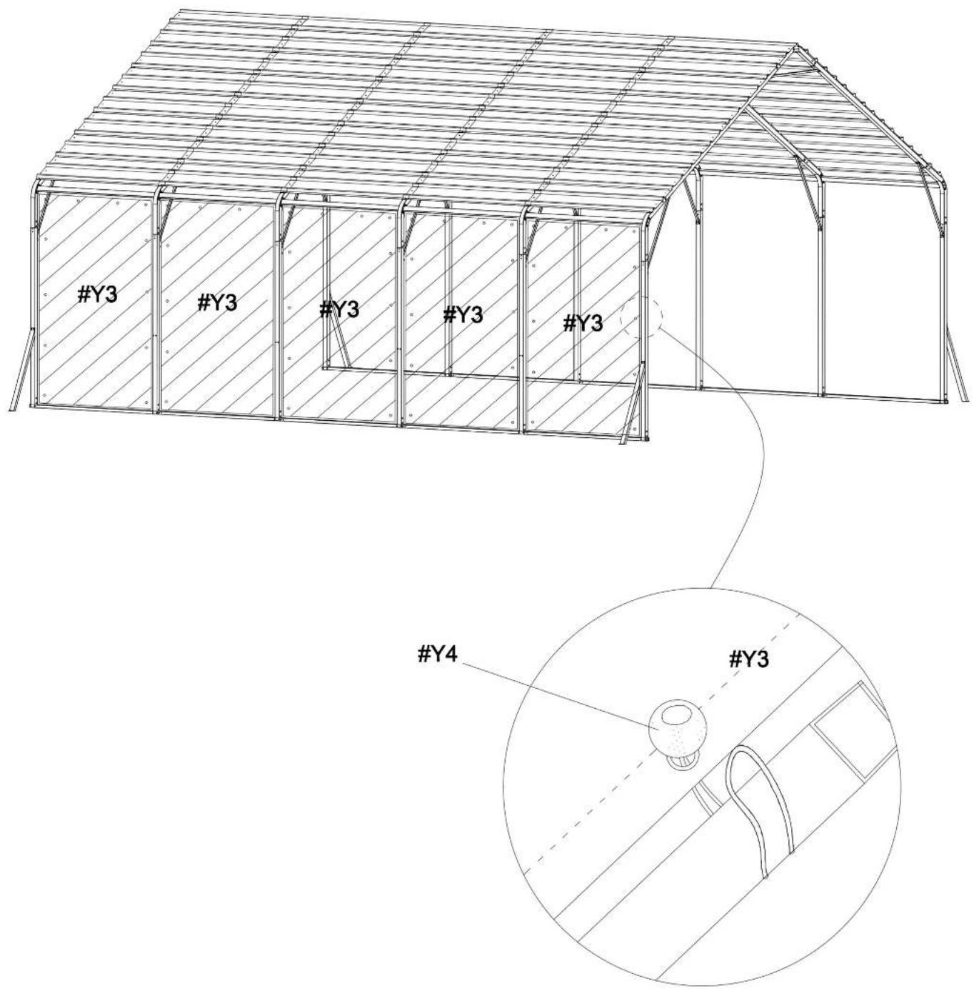
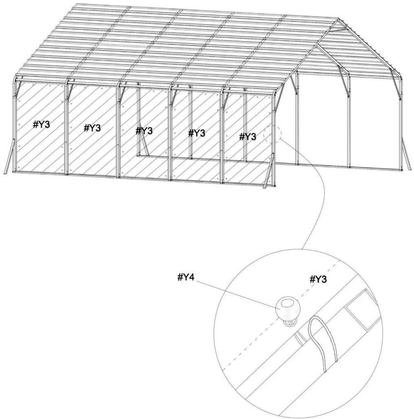
STEP 7: Reinforce the Frame
Secure 5 wall cloths (#Y3) to the frame with rope beads (#Y4)
| #Y3 | X5 | |
| #Y4 | X60 |
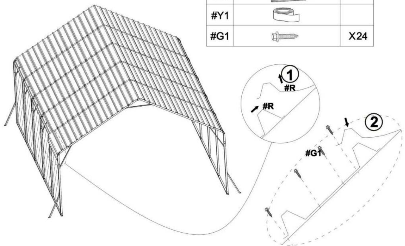
STEP8: Install the Side Roof
After installing the Leg Pole(#4), continue to install the Roof Cover (#R) in the 4 rows on the left and right sides.
1) First install the Roof Cover (#R) in the left row, as shown in the picture.
| #R | X5 | |
| #Y1 | ||
| #G1 | X24 |
Notice:
- Make sure that the screw holes are aligned, and then press the Waterproof Tape (#Y1)
- Make sure there are no gaps between the two roof covers to prevent water leakage
- The second Roof Cover (#R) needs to be placed on the first Roof Cover (#R)

2) Follow the previous steps and continue to install the Roof Cover (#R) in the remaining 1 rows on the right.

natural_image
Isometric line drawing of a steel truss structure with grid pattern (no text or symbols)| #R | 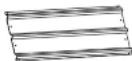 | X5 |
| #Y1 |  | |
| #G1 | 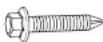 | X24 |
| #Y2 | 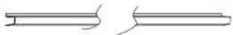 |
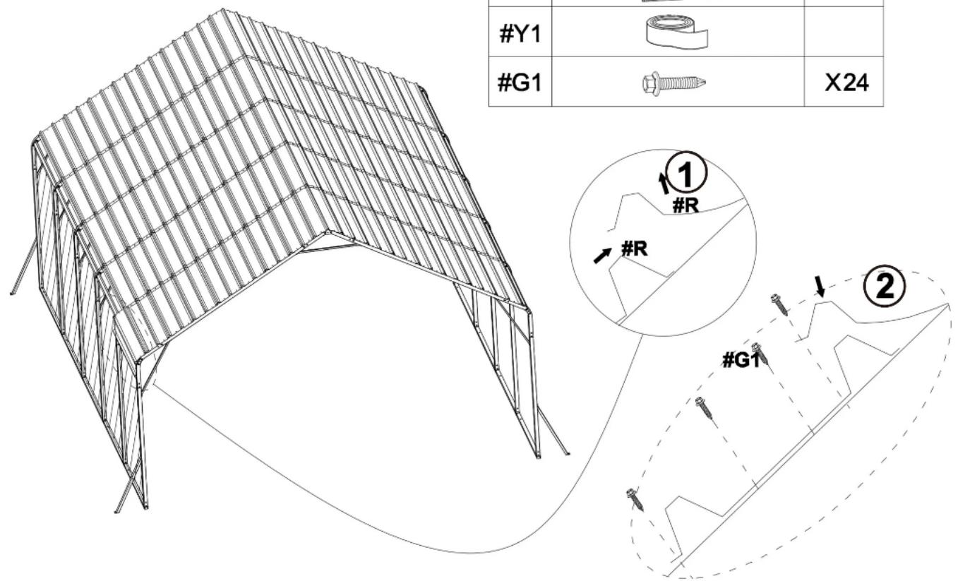
STEP9: Install the Anti-cut Tape (#Y2)
1) Wrap the Anti-cut Tape (#Y2) around the outer edge of the Roof Coveers(#R).
natural_image
Line drawing of a steel-framed modular structure with grid pattern (no text or symbols)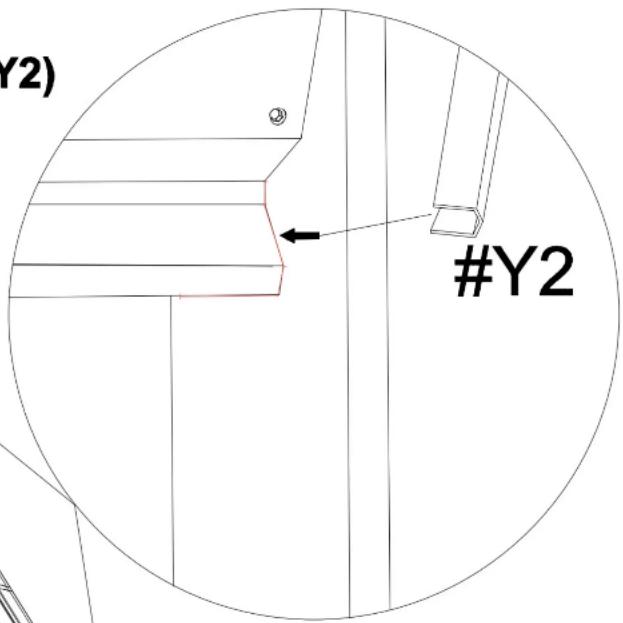
Notice:
Be careful not to start from the 4 corners when wrapping the tape. Right angles are sharp and need to be avoided.
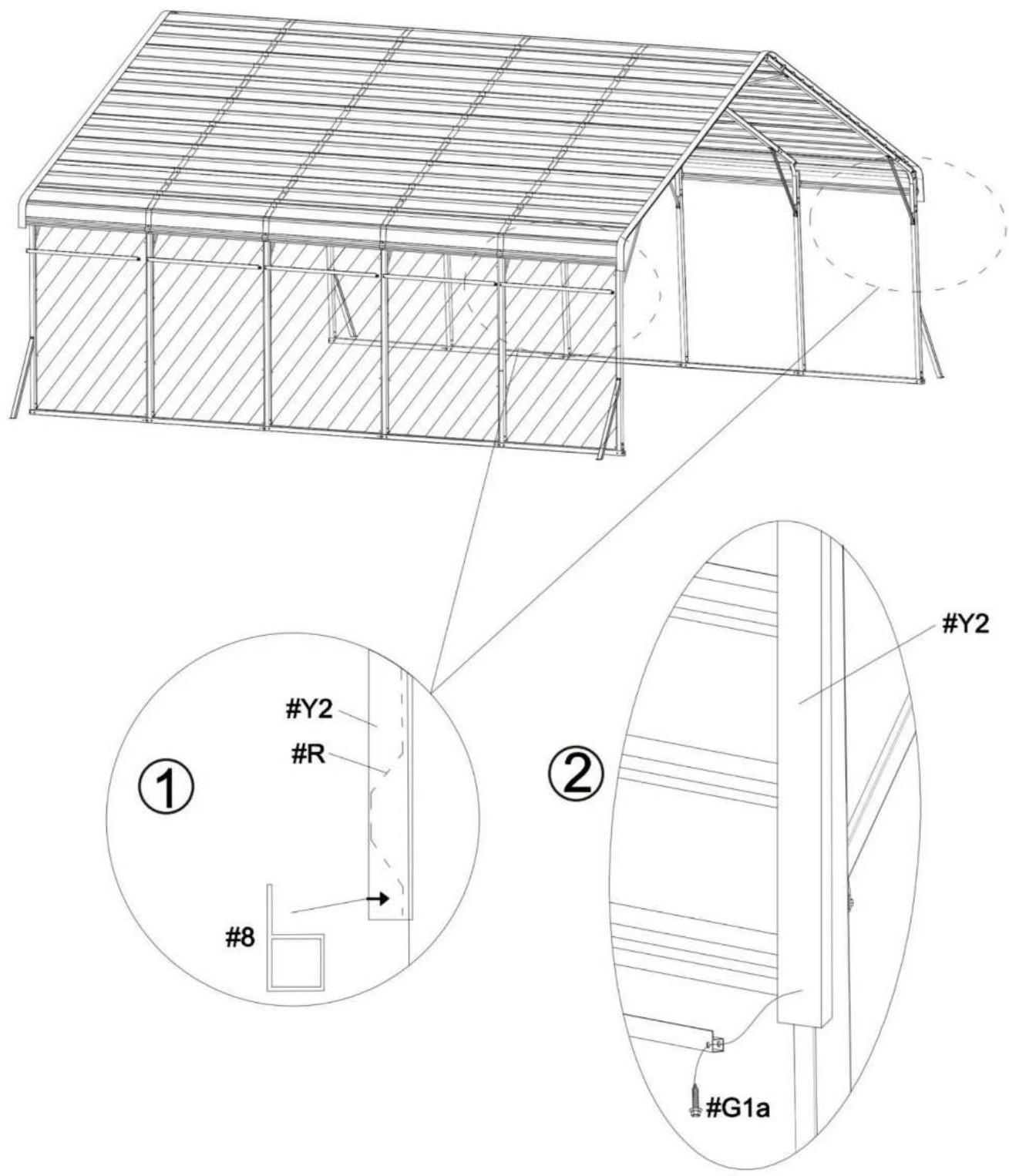
STEP10: Side-side defense pole
After installing I the Roof Cover (#R).on the left and right sides. 1) Install the Side-side defense pole(#9) in the left and right row, as shown in the picture.
| #9 | X10 | |
| #G1a | X20 |

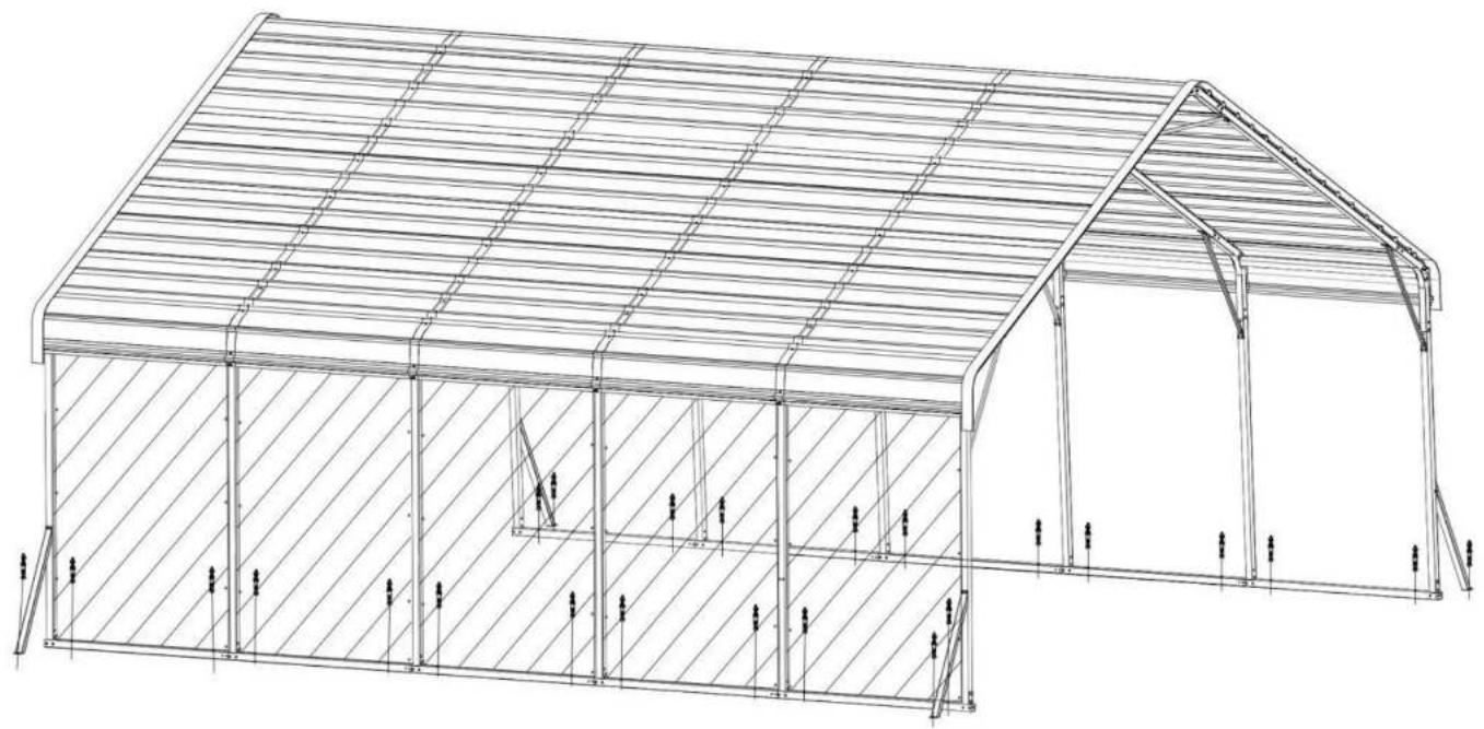
STEP11 : Anchor the Carport
Install the Anchor the Carport on the ground.
Notice:
The linking screws in this step are all: Expansion screws
| #G3 | X24 |
natural_image
Architectural line drawing of a two-story building with hatched walls and structural supports (no text or symbols)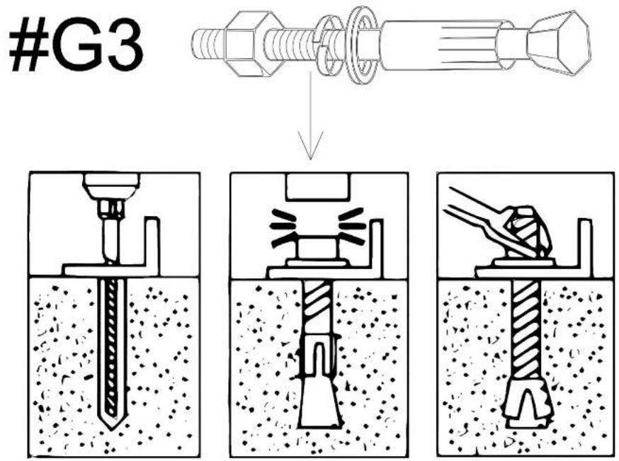

Technical Support and E-Warranty Certificate
www.vevor.com/support
VEVOR
Technical Support and E-Warranty Certificate
www.vevor.com/support
CARPORT INSTALLATION INSTRUCTION
Model : KD - TPQC -007-20x24 ft
natural_image
Architectural line drawing of a two-story building with hatched walls and arched entrance (no text or symbols)- Have at least two adults during installation. Readall instructions carefully and follow it accordingly. Failure to do so may result to injury or damage to the carport.
- Never set-up the product in rainy, windy or stormy conditions, especially lighting storms.
- Keep your carport off of thesteep sloppes and inclination.
- After installation, the carport should be anchored to prevent damage and possible injury. It is the user's responsibility to properly anchor the product.
- Aleays inspect the carport and each part before use. Make sure that everything isthighely secured. Replace any worn, defective missing parts.
- For abetter installation and use experience, it is recommended to bring your own ladder, scissors, wlectric drill and glass glue.
VEILIGHEID INSTRUCTIES
WAARSCHUWING :
BEWAAR DIT HANDMATIG
BELANGRIJK! ALSJEBLIEFT LEES DIT INSTRUCTIE ZORGVULDIG VOOR INSTALLATIE.
natural_image
Illustration of a wooden ladder with yellow shelves (no text or symbols)Ladder
natural_image
Line drawing of a pair of scissors (no text or symbols)Schaar
natural_image
Simple line drawing of a handheld electric drill (no text or symbols)Elektrische boormachine
PACKAGE CONTENTS
This carport is packed in 5 boxes. Before the installation, please check all the parts according to the part list. If there is any part missing or defective, please contact us immediately to get replacement parts.
| Part No. | Part Name | Drawing | Qty |
| #1 | Side pole 1 |  | 10PCS |
| #2 | Side pole 2 |  | 5 PCS |
| #3 | Straight peak pole | 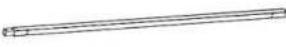 | 12 PCS |
| #4 | Leg pole | 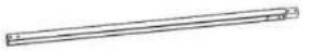 | 12 PCS |
| #5 | Top Reinforcing pole | 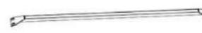 | 18 PCS |
| #6 | Ground bar 1 | 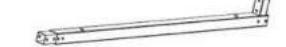 | 8 PCS |
| #6a | Ground bar 2 | 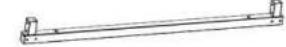 | 2 PCS |
| #7 | Connector | 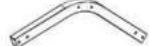 | 18 PCS |
| #8 | Ground Reinforcing pole | 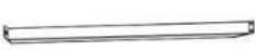 | 4 PCS |
| #9 | Side-side defense pole | 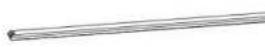 | 10 PCS |
| #10 | Side plate 1 |  | 3 PCS |
| #11 | Side plate 2 |  | 4 PCS |
| #R | Roof cover | 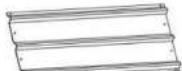 | 85 PCS |
| #G1 | M5X20 Self-Tapping screws | 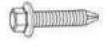 | 322PCS |
| #G1a | M5X25 Self-Tapping screws | 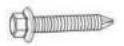 | 24 PCS |
| #G2 | Socket head bolt |  | 314 PCS |
| #G3 | Expansion screws | 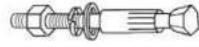 | 26 PCS |
| #G4 | Socket head bolt & Nut | 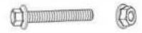 | 38 PCS |
| #L | Gloves |  | 2 pairs |
| #Y1 | Waterproof tape |  | 8 PCS |
| #Y2 | Anti-cut tape | 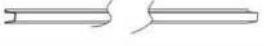 | 20 M |
| #Y3 | Enclosure |  | 5 PCS |
| #Y4 | Beads of rope | 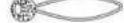 | 60 PCS |
STEP 1: Assemble the Top Frame
| #3 | 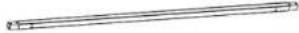 | X12 |
| #5 | 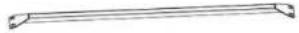 | X6 |
| #7 | 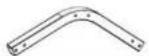 | X18 |
| #G2 | X120 |
Notice:
The linking screws in this step are all: Socket Head Bolt (#G2)

flowchart
graph TD
    A["#3"] --> B["#5"]
    B --> C["#7"]
    C --> D["#3"]
    D --> E["#7"]
    F["#2"] --> G["#G2"]
    G --> H["#3"]
    H --> I["#7"]
    style A fill:#f9f,stroke:#333
    style B fill:#f9f,stroke:#333
    style C fill:#f9f,stroke:#333
    style D fill:#f9f,stroke:#333
    style E fill:#f9f,stroke:#333
    style F fill:#f9f,stroke:#333
    style G fill:#f9f,stroke:#333
    style H fill:#f9f,stroke:#333
    style I fill:#f9f,stroke:#333
STEP 2:
| #1 | X10 | |
| #2 | X5 | |
| #10 | X3 | |
| #11 | X4 | |
| #G4 | X36 |
Notice:
The linking screws in this step are all: Socket Head Bolt (#G4)


STEP 3: Install the Top Roof
Install all the Roof Cover (#R) to the top frame. The linking screws in this step are all:Self-Tapping Screws (#G1), as shown in the picture.
Notice:
- The meaning of different coloerd holes in the Roof Cover(#R);
● Blue hole:no screws here right now.
○ Black hole: nonal installation
1) Starting from the top middle of room 1 to room 5, install the first row of Roof Covers(#R).

When installing the first piece of roof covering, place the middle slot of the tile at the gasket #10 bump for easy reinforcement with screws
| #R | 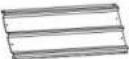 | X1 |
| #Y1 |  | X8 |
| #G1 |  | X2 |
2) When installing each Roof Cover (#R), you need to use Waterproof Tape (#Y1) as shown in the picture.

natural_image
Technical line drawing of a multi-tiered structural frame structure with no text or symbols
STEP 4:
Notice:
- Make sure that the screw holes are aligned, and then press the Waterproof Tape (#Y1)
- Make sure there are no gaps between the two roof covers to prevent water leakage
3.1) The second Roof Cover (#R) needs to be placed on the first Roof Cover (#R)
| #R |  | X4 |
| #Y1 |  | |
| #G1 |  | X10 |
3.2) Follow the previous steps and continue to install the remaining Roof Cover (#R) in the middle row.

natural_image
Technical line drawing of a structural frame with vertical supports and a central vertical component, no text or symbols present.

natural_image
Technical line drawing of a vertical structural frame with horizontal beams and supports (no text or symbols)
natural_image
Structural diagram of a multi-story building frame with horizontal beams and vertical supports, enclosed in an oval boundary (no text or symbols)4.1) After installing the middle row, continue to install the 4 rows on the right. Each newly installed Roof Cover (#R) in a row needs to be placed below the Roof Cover (#R) in the previous row, as shown in the picture.
| #R | X5 | |
| #Y1 | ||
| #G1 | X18 |
4.2) Same as the previous step, after pasting the Waterproof Tape(#Y1) of RoofCovers(#R), install the next Roof Covers(#R).

4.3) Follow the previous steps and continue to install the Roof Cover (#R) in the remaining 6 rows on the right.
| #R | X30 | |
| #Y1 | ||
| #G1 | X108 |

natural_image
Technical line drawing of a multi-tiered metal shelving unit (no text or symbols)
5.2) Same as the installation steps for the 6 rows on the right, please complete the installation of Roof Cover(#R) of the 7 rows on the left.
| #R |  | X35 |
| #Y1 |  | |
| #G1 |  | X126 |
natural_image
Architectural line drawing of a three-tiered structural frame structure (no text or symbols)
STEP 5: Connect Legs
1) Install Leg Pole(#4) and Top Reinforcing pole(#5)
to the Connector(#7).
2) The linking screws in this step are all: Hex Head Cap Bolt (#G2).

| #4 | X12 | |
| #5 | X12 | |
| #G2 | X96 |
STEP 6: Reinforce the Frame
1) Connect all the Leg Pole(#4) to Ground bar 1(#6) and Ground bar 2(#6a) 2) The linking screws in this step are all: Hex Head Cap Bolt (#G2) and Expansion screws (#G3).
| #6 | X8 | |
| #6a | X2 | |
| #8 | X4 | |
| #G2 | X88 |

natural_image
Architectural line drawing of a large arched structure with vertical supports and horizontal beams (no text or symbols)
STEP 7: Reinforce the Frame
Secure 5 wall cloths (#Y3) to the frame with rope beads (#Y4)
| #Y3 | X5 | |
| #Y4 | X60 |

STEP 8: Install the Side Roof
After installing the Leg Pole(#4), continue to install the Roof Cover (#R) in the 4 rows on the left and right sides.
1) First install the Roof Cover (#R) in the left row, as shown in the picture.
| #R | X5 | |
| #Y1 | ||
| #G1 | X24 |
Notice:
- Make sure that the screw holes are aligned, and then press the Waterproof Tape (#Y1)
- Make sure there are no gaps between the two roof covers to prevent water leakage
- The second Roof Cover (#R) needs to be placed on the first Roof Cover (#R)

2) Follow the previous steps and continue to install the Roof Cover (#R) in the remaining 1 rows on the right.

natural_image
Isometric line drawing of a steel truss structure with grid pattern (no text or symbols)| #R |  | X5 |
| #Y1 |  | |
| #G1 |  | X24 |
| #Y2 |  |
STEP9: Install the Anti-cut Tape (#Y2)
1) Wrap the Anti-cut Tape (#Y2) around the outer edge of the Roof Coveers(#R).

natural_image
Line drawing of a steel-framed industrial structure with grid pattern (no text or symbols)
Notice:
Be careful not to start from the 4 corners when wrapping the tape. Right angles are sharp and need to be avoided.
STEP10: Side-side defense pole
After installing I the Roof Cover (#R).on the left and right sides. 1) Install the Side-side defense pole(#9) in the left and right row, as shown in the picture.
| #9 | X10 | |
| #G1a | X20 |

STEP11 : Anchor the Carport
Install the Anchor the Carport on the ground.
Notice:
The linking screws in this step are all: Expansion screws
| #G3 | X24 |

natural_image
Architectural line drawing of a large industrial structure with hatched walls and support beams (no text or symbols)

www.vevor.com/support
VEVOR
Abordable. Fiable. Amélioration de l'habitat.
Technical Support and E-Warranty Certificate
www.vevor.com/support
CARPORT INSTALLATION INSTRUCTION
natural_image
Architectural line drawing of a two-story building with hatched walls and arched entrance (no text or symbols)- Have at least two adults during installation. Readall instructions carefully and follow it accordingly. Failure to do so may result to injury or damage to the carport.
- Never set-up the product in rainy, windy or stormy conditions, especially lighting storms.
- Keep your carport off of thesteep sloppes and inclination.
- After installation, the carport should be anchored to prevent damage and possible injury. It is the user's responsibility to properly anchor the product.
- Aleays inspect the carport and each part before use. Make sure that everything isthighely secured. Replace any worn, defective missing parts.
- For abetter installation and use experience, it is recommended to bring your own ladder, scissors, wlectric drill and glass glue.
SÉCURITÉ INSTRUCTIONS
AVERTISSEMENT :
natural_image
Illustration of a wooden ladder with four yellow shelves (no text or symbols)Échelle

natural_image
Line drawing of a pair of scissors (no text or symbols)Ciseaux

natural_image
Simple line drawing of a handheld electric drill (no text or symbols)Perceuse électrique
PACKAGE CONTENTS
This carport is packed in 5 boxes. Before the installation, please check all the parts according to the part list. If there is any part missing or defective, please contact us immediately to get replacement parts.
| Part No. | Part Name | Drawing | Qty |
| #1 | Side pole 1 | | 10PCS |
| #2 | Side pole 2 | | 5 PCS |
| #3 | Straight peak pole | | 12 PCS |
| #4 | Leg pole | | 12 PCS |
| #5 | Top Reinforcing pole | | 18 PCS |
| #6 | Ground bar 1 | | 8 PCS |
| #6a | Ground bar 2 | | 2 PCS |
| #7 | Connector | | 18 PCS |
| #8 | Ground Reinforcing pole | | 4 PCS |
| #9 | Side-side defense pole | | 10 PCS |
| #10 | Side plate 1 | | 3 PCS |
| #11 | Side plate 2 | | 4 PCS |
| #R | Roof cover | | 85 PCS |
| #G1 | M5X20 Self-Tapping screws | [ZDX] | 322PCS |
| #G1a | M5X25 Self-Tapping screws | | 24 PCS |
| #G2 | Socket head bolt | | 314 PCS |
| #G3 | Expansion screws | | 26 PCS |
| #G4 | Socket head bolt & Nut | | 38 PCS |
| #L | Gloves | | 2 pairs |
| #Y1 | Waterproof tape | | 8 PCS |
| #Y2 | Anti-cut tape | | 20 M |
| #Y3 | Enclosure | | 5 PCS |
| #Y4 | Beads of rope | | 60 PCS |
STEP 1: Assemble the Top Frame
| #3 | | X12 |
| #5 | | X6 |
| #7 | | X18 |
| #G2 | X120 |
Notice:
The linking screws in this step are all: Socket Head Bolt (#G2)

flowchart
graph TD
    A["#3"] --> B["#5"]
    B --> C["#7"]
    C --> D["#3"]
    D --> E["#7"]
    F["#2"] --> G["#G2"]
    G --> H["#3"]
    H --> I["#7"]
    style A fill:#f9f,stroke:#333
    style B fill:#f9f,stroke:#333
    style C fill:#f9f,stroke:#333
    style D fill:#f9f,stroke:#333
    style E fill:#f9f,stroke:#333
    style F fill:#f9f,stroke:#333
    style G fill:#f9f,stroke:#333
    style H fill:#f9f,stroke:#333
    style I fill:#f9f,stroke:#333
STEP 2:
| #1 | X10 | |
| #2 | X5 | |
| #10 | X3 | |
| #11 | X4 | |
| #G4 | X36 |
Notice:
The linking screws in this step are all: Socket Head Bolt (#G4)

STEP 3: Install the Top Roof
Install all the Roof Cover (#R) to the top frame. The linking screws in this step are all:Self-Tapping Screws (#G1), as shown in the picture.
Notice:
- The meaning of different coloerd holes in the Roof Cover(#R);
● Blue hole:no screws here right now.
○ Black hole: nonal installation
1) Starting from the top middle of room 1 to room 5, install the first row of Roof Covers(#R).


When installing the first piece of roof covering, place the middle slot of the tile at the gasket #10 bump for easy reinforcement with screws
| #R | | X1 |
| #Y1 | | X8 |
| #G1 | | X2 |
2) When installing each Roof Cover (#R), you need to use Waterproof Tape (#Y1) as shown in the picture.

natural_image
Technical line drawing of a multi-tiered structural frame structure with no text or symbols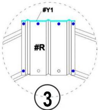
STEP 4:
Notice:
- Make sure that the screw holes are aligned, and then press the Waterproof Tape (#Y1)
- Make sure there are no gaps between the two roof covers to prevent water leakage
3.1) The second Roof Cover (#R) needs to be placed on the first Roof Cover (#R)
| #R | | X4 |
| #Y1 | | |
| #G1 | | X10 |
3.2) Follow the previous steps and continue to install the remaining Roof Cover (#R) in the middle row.

natural_image
Technical line drawing of a structural frame with vertical supports and a central vertical component, no text or symbols present.

natural_image
Technical line drawing of a vertical structural frame with horizontal beams and supports (no text or symbols)
natural_image
Structural diagram of a multi-story building frame with horizontal beams and vertical supports, enclosed in an oval boundary (no text or symbols)4.1) After installing the middle row, continue to install the 4 rows on the right. Each newly installed Roof Cover (#R) in a row needs to be placed below the Roof Cover (#R) in the previous row, as shown in the picture.

| #R | X5 | |
| #Y1 | ||
| #G1 | X18 |
4.2) Same as the previous step, after pasting the Waterproof Tape(#Y1) of RoofCovers(#R), install the next Roof Covers(#R).
4.3) Follow the previous steps and continue to install the Roof Cover (#R) in the remaining 6 rows on the right.
| #R | X30 | |
| #Y1 | ||
| #G1 | X108 |
natural_image
Technical line drawing of a multi-tiered metal shelving unit (no text or symbols)
5.2) Same as the installation steps for the 6 rows on the right, please complete the installation of Roof Cover(#R) of the 7 rows on the left.
| #R | | X35 |
| #Y1 | | |
| #G1 | | X126 |

natural_image
Architectural line drawing of a three-tiered structural frame structure (no text or symbols)
STEP 5: Connect Legs
1) Install Leg Pole(#4) and Top Reinforcing pole(#5)
to the Connector(#7).
2) The linking screws in this step are all: Hex Head Cap Bolt (#G2).

| #4 | X12 | |
| #5 | X12 | |
| #G2 | X96 |
STEP 6: Reinforce the Frame
1) Connect all the Leg Pole(#4) to Ground bar 1(#6) and Ground bar 2(#6a) 2) The linking screws in this step are all: Hex Head Cap Bolt (#G2) and Expansion screws (#G3).
| #6 | X8 | |
| #6a | X2 | |
| #8 | X4 | |
| #G2 | X88 |
natural_image
Architectural line drawing of a large arched structure with vertical supports and horizontal beams (no text or symbols)
STEP 7: Reinforce the Frame
Secure 5 wall cloths (#Y3) to the frame with rope beads (#Y4)
| #Y3 | X5 | |
| #Y4 | X60 |

STEP 8: Install the Side Roof
After installing the Leg Pole(#4), continue to install the Roof Cover (#R) in the 4 rows on the left and right sides.
1) First install the Roof Cover (#R) in the left row, as shown in the picture.
| #R | X5 | |
| #Y1 | ||
| #G1 | X24 |

Notice:
- Make sure that the screw holes are aligned, and then press the Waterproof Tape (#Y1)
- Make sure there are no gaps between the two roof covers to prevent water leakage
- The second Roof Cover (#R) needs to be placed on the first Roof Cover (#R)

2) Follow the previous steps and continue to install the Roof Cover (#R) in the remaining 1 rows on the right.

natural_image
Isometric line drawing of a steel truss structure with grid pattern (no text or symbols)| #R | | X5 |
| #Y1 | | |
| #G1 | | X24 |
| #Y2 |  |
STEP9: Install the Anti-cut Tape (#Y2)
1) Wrap the Anti-cut Tape (#Y2) around the outer edge of the Roof Coveers(#R).

natural_image
Line drawing of a steel-framed industrial structure with grid pattern (no text or symbols)
Notice:
Be careful not to start from the 4 corners when wrapping the tape. Right angles are sharp and need to be avoided.
STEP10: Side-side defense pole
After installing I the Roof Cover (#R).on the left and right sides. 1) Install the Side-side defense pole(#9) in the left and right row, as shown in the picture.
| #9 | X10 | |
| #G1a | X20 |

STEP11 : Anchor the Carport
Install the Anchor the Carport on the ground.
Notice:
The linking screws in this step are all: Expansion screws
| #G3 | X24 |

natural_image
Architectural line drawing of a large industrial structure with hatched walls and support beams (no text or symbols)

Technique Soutien et E - Garantie Certificat www.vevor.com/support
VEVOR
Technical Support and E-Warranty Certificate
www.vevor.com/support
CARPORT INSTALLATION INSTRUCTION
Modell : KD - TPQC -007-20x24 ft

natural_image
Architectural line drawing of a two-story building with hatched walls and arched entrance (no text or symbols)- Have at least two adults during installation. Readall instructions carefully and follow it accordingly. Failure to do so may result to injury or damage to the carport.
- Never set-up the product in rainy, windy or stormy conditions, especially lighting storms.
- Keep your carport off of thesteep sloppes and inclination.
- After installation, the carport should be anchored to prevent damage and possible injury. It is the user's responsibility to properly anchor the product.
- Aleays inspect the carport and each part before use. Make sure that everything isthighely secured. Replace any worn, defective missing parts.
- For abetter installation and use experience, it is recommended to bring your own ladder, scissors, wlectric drill and glass glue.
natural_image
Illustration of a wooden ladder with four yellow shelves (no text or symbols)Leiter
natural_image
Line drawing of a pair of scissors (no text or symbols)Schere

natural_image
Simple line drawing of a handheld electric drill (no text or symbols)This carport is packed in 5 boxes. Before the installation, please check all the parts according to the part list. If there is any part missing or defective, please contact us immediately to get replacement parts.
| Part No. | Part Name | Drawing | Qty |
| #1 | Side pole 1 | | 10PCS |
| #2 | Side pole 2 | | 5 PCS |
| #3 | Straight peak pole | | 12 PCS |
| #4 | Leg pole | | 12 PCS |
| #5 | Top Reinforcing pole | | 18 PCS |
| #6 | Ground bar 1 | | 8 PCS |
| #6a | Ground bar 2 | | 2 PCS |
| #7 | Connector | | 18 PCS |
| #8 | Ground Reinforcing pole | | 4 PCS |
| #9 | Side-side defense pole | | 10 PCS |
| #10 | Side plate 1 | | 3 PCS |
| #11 | Side plate 2 | | 4 PCS |
| #R | Roof cover | | 85 PCS |
| #G1 | M5X20 Self-Tapping screws | | 322PCS |
| #G1a | M5X25 Self-Tapping screws | | 24 PCS |
| #G2 | Socket head bolt | | 314 PCS |
| #G3 | Expansion screws | | 26 PCS |
| #G4 | Socket head bolt & Nut | | 38 PCS |
| #L | Gloves | | 2 pairs |
| #Y1 | Waterproof tape | | 8 PCS |
| #Y2 | Anti-cut tape | | 20 M |
| #Y3 | Enclosure | | 5 PCS |
| #Y4 | Beads of rope | | 60 PCS |
STEP 1: Assemble the Top Frame
| #3 |  | X12 |
| #5 | 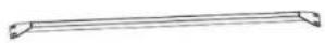 | X6 |
| #7 | 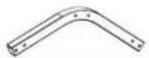 | X18 |
| #G2 | X120 |
Notice:
The linking screws in this step are all: Socket Head Bolt (#G2)
flowchart
graph TD
    A["#3"] --> B["#5"]
    B --> C["#7"]
    C --> D["#3"]
    D --> E["#7"]
    F["#2"] --> G["#G2"]
    G --> H["#3"]
    H --> I["#7"]
    style A fill:#f9f,stroke:#333
    style B fill:#f9f,stroke:#333
    style C fill:#f9f,stroke:#333
    style D fill:#f9f,stroke:#333
    style E fill:#f9f,stroke:#333
    style F fill:#f9f,stroke:#333
    style G fill:#f9f,stroke:#333
    style H fill:#f9f,stroke:#333
    style I fill:#f9f,stroke:#333
STEP 2:
| #1 | X10 | |
| #2 | X5 | |
| #10 | X3 | |
| #11 | X4 | |
| #G4 | X36 |
Notice:
The linking screws in this step are all: Socket Head Bolt (#G4)


STEP 3: Install the Top Roof
Install all the Roof Cover (#R) to the top frame. The linking screws in this step are all:Self-Tapping Screws (#G1), as shown in the picture.
Notice:
- The meaning of different coloerd holes in the Roof Cover(#R);
● Blue hole:no screws here right now.
○ Black hole: nonal installation
1) Starting from the top middle of room 1 to room 5, install the first row of Roof Covers(#R).

When installing the first piece of roof covering, place the middle slot of the tile at the gasket #10 bump for easy reinforcement with screws
| #R | 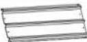 | X1 |
| #Y1 |  | X8 |
| #G1 |  | X2 |
2) When installing each Roof Cover (#R), you need to use Waterproof Tape (#Y1) as shown in the picture.

natural_image
Technical line drawing of a multi-tiered structural frame structure with no text or symbols
STEP 4:
Notice:
- Make sure that the screw holes are aligned, and then press the Waterproof Tape (#Y1)
- Make sure there are no gaps between the two roof covers to prevent water leakage
3.1) The second Roof Cover (#R) needs to be placed on the first Roof Cover (#R)
| #R | | X4 |
| #Y1 | | |
| #G1 | | X10 |
3.2) Follow the previous steps and continue to install the remaining Roof Cover (#R) in the middle row.
natural_image
Technical line drawing of a multi-tiered structural frame with a central vertical component and dashed oval detail (no text or symbols)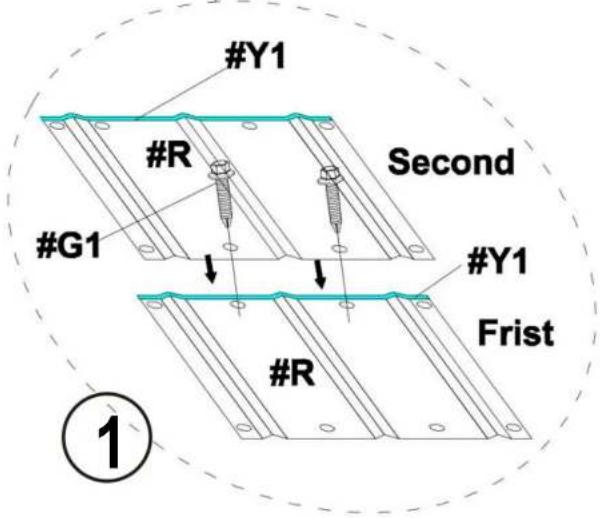
natural_image
Technical line drawing of a vertical structural frame with horizontal beams and supports (no text or symbols)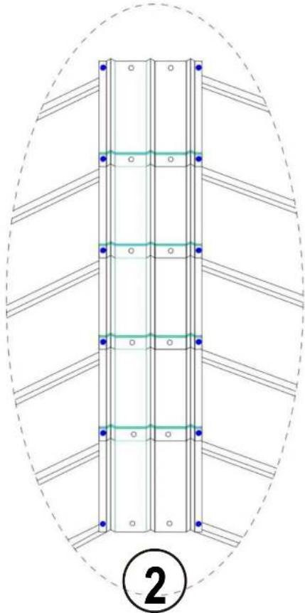
natural_image
Structural diagram of a multi-story building frame with horizontal beams and vertical supports, enclosed in an oval boundary (no text or symbols)4.1) After installing the middle row, continue to install the 4 rows on the right. Each newly installed Roof Cover (#R) in a row needs to be placed below the Roof Cover (#R) in the previous row, as shown in the picture.
| #R | X5 | |
| #Y1 | ||
| #G1 | X18 |
4.2) Same as the previous step, after pasting the Waterproof Tape(#Y1) of RoofCovers(#R), install the next Roof Covers(#R).

natural_image
Technical line drawing of a structural frame with vertical supports and a curved dashed oval overlay (no text or symbols)
4.3) Follow the previous steps and continue to install the Roof Cover (#R) in the remaining 6 rows on the right.
| #R | X30 | |
| #Y1 | ||
| #G1 | X108 |

natural_image
Technical line drawing of a multi-tiered metal shelving unit (no text or symbols)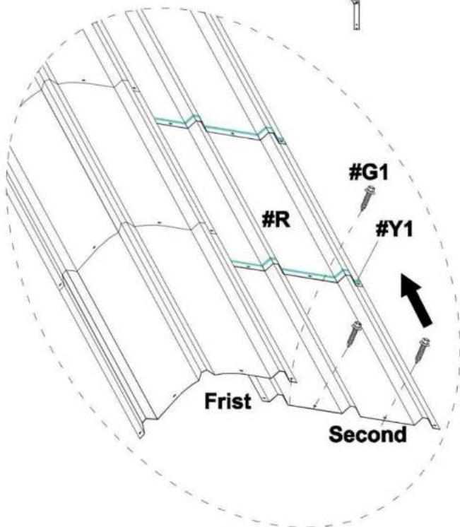
5.2) Same as the installation steps for the 6 rows on the right, please complete the installation of Roof Cover(#R) of the 7 rows on the left.
| #R | | X35 |
| #Y1 |  | |
| #G1 |  | X126 |

natural_image
Architectural line drawing of a three-tiered structural frame structure (no text or symbols)
STEP 5: Connect Legs
1) Install Leg Pole(#4) and Top Reinforcing pole(#5)
to the Connector(#7).
2) The linking screws in this step are all: Hex Head Cap Bolt (#G2).

| #4 | X12 | |
| #5 | X12 | |
| #G2 | X96 |
STEP 6: Reinforce the Frame
1) Connect all the Leg Pole(#4) to Ground bar 1(#6) and Ground bar 2(#6a) 2) The linking screws in this step are all: Hex Head Cap Bolt (#G2) and Expansion screws (#G3).
| #6 | X8 | |
| #6a | X2 | |
| #8 | X4 | |
| #G2 | X88 |

natural_image
Architectural line drawing of a large arched structure with vertical supports and horizontal beams (no text or symbols)
STEP 7: Reinforce the Frame
Secure 5 wall cloths (#Y3) to the frame with rope beads (#Y4)
| #Y3 | X5 | |
| #Y4 | X60 |

STEP 8: Install the Side Roof
After installing the Leg Pole(#4), continue to install the Roof Cover (#R) in the 4 rows on the left and right sides.
1) First install the Roof Cover (#R) in the left row, as shown in the picture.
| #R | X5 | |
| #Y1 | ||
| #G1 | X24 |

Notice:
- Make sure that the screw holes are aligned, and then press the Waterproof Tape (#Y1)
- Make sure there are no gaps between the two roof covers to prevent water leakage
- The second Roof Cover (#R) needs to be placed on the first Roof Cover (#R)

2) Follow the previous steps and continue to install the Roof Cover (#R) in the remaining 1 rows on the right.

natural_image
Isometric line drawing of a steel truss structure with grid pattern (no text or symbols)| #R | | X5 |
| #Y1 |  | |
| #G1 | | X24 |
| #Y2 | |
STEP9: Install the Anti-cut Tape (#Y2)
1) Wrap the Anti-cut Tape (#Y2) around the outer edge of the Roof Coveers(#R).

natural_image
Line drawing of a steel-framed industrial structure with grid pattern (no text or symbols)
Notice:
Be careful not to start from the 4 corners when wrapping the tape. Right angles are sharp and need to be avoided.
STEP10: Side-side defense pole
After installing I the Roof Cover (#R).on the left and right sides. 1) Install the Side-side defense pole(#9) in the left and right row, as shown in the picture.
| #9 | X10 | |
| #G1a | X20 |

STEP11 : Anchor the Carport
Install the Anchor the Carport on the ground.
Notice:
The linking screws in this step are all: Expansion screws
| #G3 | X24 |

natural_image
Architectural line drawing of a large industrial structure with hatched walls and support beams (no text or symbols)

www.vevor.com/support
VEVOR
Technical Support and E-Warranty Certificate www.vevor.com/support
CARPORT INSTALLATION INSTRUCTION
Modelka : KD - TPQC -007-20x24 stopy

natural_image
Architectural line drawing of a two-story building with hatched walls and arched entrance (no text or symbols)- Have at least two adults during installation. Readall instructions carefully and follow it accordingly. Failure to do so may result to injury or damage to the carport.
- Never set-up the product in rainy, windy or stormy conditions, especially lighting storms.
- Keep your carport off of thesteep sloppes and inclination.
- After installation, the carport should be anchored to prevent damage and possible injury. It is the user's responsibility to properly anchor the product.
- Aleays inspect the carport and each part before use. Make sure that everything isthighely secured. Replace any worn, defective missing parts.
- For abetter installation and use experience, it is recommended to bring your own ladder, scissors, wlect-ic drill and glass glue.
BEZPIECZEŃSTWO INSTRUKCJE
OSTRZEŻENIE :
natural_image
Illustration of a wooden ladder with yellow shelves (no text or symbols)Drabina

natural_image
Line drawing of a pair of scissors (no text or symbols)Nożyczki

natural_image
Simple line drawing of a handheld electric drill (no text or symbols)This carport is packed in 5 boxes. Before the installation, please check all the parts according to the part list. If there is any part missing or defective, please contact us immediately to get replacement parts.
| Part No. | Part Name | Drawing | Qty |
| #1 | Side pole 1 | | 10PCS |
| #2 | Side pole 2 | | 5 PCS |
| #3 | Straight peak pole | | 12 PCS |
| #4 | Leg pole | | 12 PCS |
| #5 | Top Reinforcing pole | | 18 PCS |
| #6 | Ground bar 1 | | 8 PCS |
| #6a | Ground bar 2 | | 2 PCS |
| #7 | Connector | | 18 PCS |
| #8 | Ground Reinforcing pole | | 4 PCS |
| #9 | Side-side defense pole | | 10 PCS |
| #10 | Side plate 1 | | 3 PCS |
| #11 | Side plate 2 | | 4 PCS |
| #R | Roof cover | | 85 PCS |
| #G1 | M5X20 Self-Tapping screws | | 322PCS |
| #G1a | M5X25 Self-Tapping screws | | 24 PCS |
| #G2 | Socket head bolt | | 314 PCS |
| #G3 | Expansion screws | | 26 PCS |
| #G4 | Socket head bolt & Nut | | 38 PCS |
| #L | Gloves | | 2 pairs |
| #Y1 | Waterproof tape | | 8 PCS |
| #Y2 | Anti-cut tape | | 20 M |
| #Y3 | Enclosure | | 5 PCS |
| #Y4 | Beads of rope | | 60 PCS |
STEP 1: Assemble the Top Frame
| #3 | | X12 |
| #5 | | X6 |
| #7 | | X18 |
| #G2 | X120 |
Notice:
The linking screws in this step are all: Socket Head Bolt (#G2)

flowchart
graph TD
    A["#3"] --> B["#5"]
    B --> C["#7"]
    C --> D["#3"]
    D --> E["#7"]
    F["#2"] --> G["#G2"]
    G --> H["#3"]
    H --> I["#7"]
    style A fill:#f9f,stroke:#333
    style B fill:#f9f,stroke:#333
    style C fill:#f9f,stroke:#333
    style D fill:#f9f,stroke:#333
    style E fill:#f9f,stroke:#333
    style F fill:#f9f,stroke:#333
    style G fill:#f9f,stroke:#333
    style H fill:#f9f,stroke:#333
    style I fill:#f9f,stroke:#333
STEP 2:
| #1 | X10 | |
| #2 | X5 | |
| #10 | X3 | |
| #11 | X4 | |
| #G4 | X36 |
Notice:
The linking screws in this step are all: Socket Head Bolt (#G4)


STEP 3: Install the Top Roof
Install all the Roof Cover (#R) to the top frame. The linking screws in this step are all:Self-Tapping Screws (#G1), as shown in the picture.
Notice:
- The meaning of different coloerd holes in the Roof Cover(#R);
● Blue hole:no screws here right now.
○ Black hole: nonal installation
1) Starting from the top middle of room 1 to room 5, install the first row of Roof Covers(#R).


When installing the first piece of roof covering, place the middle slot of the tile at the gasket #10 bump for easy reinforcement with screws
| #R | | X1 |
| #Y1 | | X8 |
| #G1 | | X2 |
2) When installing each Roof Cover (#R), you need to use Waterproof Tape (#Y1) as shown in the picture.

natural_image
Technical line drawing of a multi-tiered structural frame structure with no text or symbols
STEP 4:
Notice:
- Make sure that the screw holes are aligned, and then press the Waterproof Tape (#Y1)
- Make sure there are no gaps between the two roof covers to prevent water leakage
3.1) The second Roof Cover (#R) needs to be placed on the first Roof Cover (#R)
| #R | | X4 |
| #Y1 | | |
| #G1 | | X10 |
3.2) Follow the previous steps and continue to install the remaining Roof Cover (#R) in the middle row.

natural_image
Technical line drawing of a structural frame with vertical supports and a central vertical component, no text or symbols present.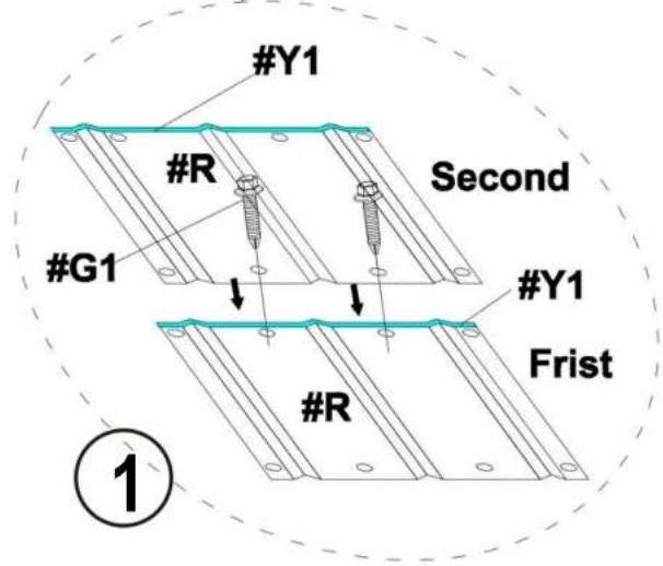

natural_image
Technical line drawing of a vertical structural frame with horizontal beams and supports (no text or symbols)
natural_image
Structural diagram of a multi-story building frame with horizontal beams and vertical supports, enclosed in an oval boundary (no text or symbols)4.1) After installing the middle row, continue to install the 4 rows on the right. Each newly installed Roof Cover (#R) in a row needs to be placed below the Roof Cover (#R) in the previous row, as shown in the picture.

| #R | X5 | |
| #Y1 | ||
| #G1 | X18 |
4.2) Same as the previous step, after pasting the Waterproof Tape(#Y1) of RoofCovers(#R), install the next Roof Covers(#R).

natural_image
Technical line drawing of a structural frame with vertical supports and a curved dashed oval overlay (no text or symbols)
4.3) Follow the previous steps and continue to install the Roof Cover (#R) in the remaining 6 rows on the right.
| #R | X30 | |
| #Y1 | ||
| #G1 | X108 |

natural_image
Technical line drawing of a multi-tiered metal shelving unit (no text or symbols)
5.2) Same as the installation steps for the 6 rows on the right, please complete the installation of Roof Cover(#R) of the 7 rows on the left.
| #R | | X35 |
| #Y1 | | |
| #G1 | | X126 |

natural_image
Architectural line drawing of a three-tiered structural frame structure (no text or symbols)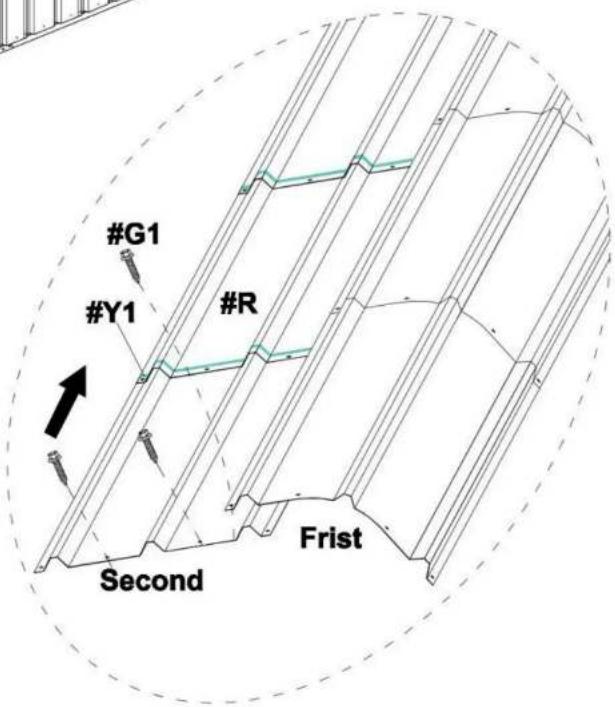
STEP 5: Connect Legs
1) Install Leg Pole(#4) and Top Reinforcing pole(#5)
to the Connector(#7).
2) The linking screws in this step are all: Hex Head Cap Bolt (#G2).

| #4 | X12 | |
| #5 | X12 | |
| #G2 | X96 |
STEP 6: Reinforce the Frame
1) Connect all the Leg Pole(#4) to Ground bar 1(#6) and Ground bar 2(#6a) 2) The linking screws in this step are all: Hex Head Cap Bolt (#G2) and Expansion screws (#G3).
| #6 | X8 | |
| #6a | X2 | |
| #8 | X4 | |
| #G2 | X88 |

natural_image
Architectural line drawing of a large arched structure with vertical supports and horizontal beams (no text or symbols)
STEP 7: Reinforce the Frame
Secure 5 wall cloths (#Y3) to the frame with rope beads (#Y4)
| #Y3 | X5 | |
| #Y4 | X60 |
STEP 8: Install the Side Roof
After installing the Leg Pole(#4), continue to install the Roof Cover (#R) in the 4 rows on the left and right sides.
1) First install the Roof Cover (#R) in the left row, as shown in the picture.
| #R | X5 | |
| #Y1 | ||
| #G1 | X24 |

Notice:
- Make sure that the screw holes are aligned, and then press the Waterproof Tape (#Y1)
- Make sure there are no gaps between the two roof covers to prevent water leakage
- The second Roof Cover (#R) needs to be placed on the first Roof Cover (#R)
2) Follow the previous steps and continue to install the Roof Cover (#R) in the remaining 1 rows on the right.

natural_image
Isometric line drawing of a steel truss structure with grid pattern (no text or symbols)| #R | | X5 |
| #Y1 | | |
| #G1 | | X24 |
| #Y2 | |
STEP9: Install the Anti-cut Tape (#Y2)
1) Wrap the Anti-cut Tape (#Y2) around the outer edge of the Roof Coveers(#R).

natural_image
Line drawing of a steel-framed industrial structure with grid pattern (no text or symbols)
Notice:
Be careful not to start from the 4 corners when wrapping the tape. Right angles are sharp and need to be avoided.
STEP10: Side-side defense pole
After installing I the Roof Cover (#R).on the left and right sides. 1) Install the Side-side defense pole(#9) in the left and right row, as shown in the picture.
| #9 | X10 | |
| #G1a | X20 |

STEP11 : Anchor the Carport
Install the Anchor the Carport on the ground.
Notice:
The linking screws in this step are all: Expansion screws
| #G3 | X24 |
natural_image
Architectural line drawing of a large industrial structure with hatched walls and support beams (no text or symbols)

Technical Support and E-Warranty Certificate
www.vevor.com/support
CARPORT INSTALLATION INSTRUCTION
Modello : KD - TPQC -007-20x24 piedi

natural_image
Architectural line drawing of a two-story building with hatched walls and arched entrance (no text or symbols)- Have at least two adults during installation. Readall instructions carefully and follow it accordingly. Failure to do so may result to injury or damage to the carport.
- Never set-up the product in rainy, windy or stormy conditions, especially lighting storms.
- Keep your carport off of thesteep sloppes and inclination.
- After installation, the carport should be anchored to prevent damage and possible injury. It is the user's responsibility to properly anchor the product.
- Aleays inspect the carport and each part before use. Make sure that everything isthighely secured. Replace any worn, defective missing parts.
- For abetter installation and use experience, it is recommended to bring your own ladder, scissors, wlect-ic drill and glass glue.
SICUREZZA ISTRUZIONI
AVVERTIMENTO :
natural_image
Illustration of a wooden ladder with three yellow shelves (no text or symbols)Scala
natural_image
Line drawing of a pair of scissors (no text or symbols)Forbici

natural_image
Simple line drawing of a handheld electric drill (no text or symbols)Trapano elettrico
PACKAGE CONTENTS
This carport is packed in 5 boxes. Before the installation, please check all the parts according to the part list. If there is any part missing or defective, please contact us immediately to get replacement parts.
| Part No. | Part Name | Drawing | Qty |
| #1 | Side pole 1 | | 10PCS |
| #2 | Side pole 2 | | 5 PCS |
| #3 | Straight peak pole | | 12 PCS |
| #4 | Leg pole | | 12 PCS |
| #5 | Top Reinforcing pole | | 18 PCS |
| #6 | Ground bar 1 | | 8 PCS |
| #6a | Ground bar 2 | | 2 PCS |
| #7 | Connector | | 18 PCS |
| #8 | Ground Reinforcing pole | | 4 PCS |
| #9 | Side-side defense pole | | 10 PCS |
| #10 | Side plate 1 | | 3 PCS |
| #11 | Side plate 2 | | 4 PCS |
| #R | Roof cover | | 85 PCS |
| #G1 | M5X20 Self-Tapping screws | | 322PCS |
| #G1a | M5X25 Self-Tapping screws | | 24 PCS |
| #G2 | Socket head bolt | | 314 PCS |
| #G3 | Expansion screws | | 26 PCS |
| #G4 | Socket head bolt & Nut | | 38 PCS |
| #L | Gloves | | 2 pairs |
| #Y1 | Waterproof tape | | 8 PCS |
| #Y2 | Anti-cut tape | | 20 M |
| #Y3 | Enclosure | | 5 PCS |
| #Y4 | Beads of rope | | 60 PCS |
STEP 1: Assemble the Top Frame
| #3 | | X12 |
| #5 | | X6 |
| #7 | | X18 |
| #G2 | X120 |
Notice:
The linking screws in this step are all: Socket Head Bolt (#G2)

flowchart
graph TD
    A["#3"] --> B["#5"]
    B --> C["#7"]
    C --> D["#3"]
    D --> E["#7"]
    F["#2"] --> G["#G2"]
    G --> H["#3"]
    H --> I["#7"]
    style A fill:#f9f,stroke:#333
    style B fill:#f9f,stroke:#333
    style C fill:#f9f,stroke:#333
    style D fill:#f9f,stroke:#333
    style E fill:#f9f,stroke:#333
    style F fill:#f9f,stroke:#333
    style G fill:#f9f,stroke:#333
    style H fill:#f9f,stroke:#333
    style I fill:#f9f,stroke:#333
STEP 2:
| #1 | X10 | |
| #2 | X5 | |
| #10 | X3 | |
| #11 | X4 | |
| #G4 | X36 |
Notice:
The linking screws in this step are all: Socket Head Bolt (#G4)


STEP 3: Install the Top Roof
Install all the Roof Cover (#R) to the top frame. The linking screws in this step are all:Self-Tapping Screws (#G1), as shown in the picture.
Notice:
- The meaning of different coloerd holes in the Roof Cover(#R);
● Blue hole:no screws here right now.
○ Black hole: nonal installation
1) Starting from the top middle of room 1 to room 5, install the first row of Roof Covers(#R).


When installing the first piece of roof covering, place the middle slot of the tile at the gasket #10 bump for easy reinforcement with screws
| #R | | X1 |
| #Y1 | | X8 |
| #G1 | | X2 |
2) When installing each Roof Cover (#R), you need to use Waterproof Tape (#Y1) as shown in the picture.
natural_image
Technical line drawing of a multi-tiered structural frame structure with no text or symbols
STEP 4:
Notice:
- Make sure that the screw holes are aligned, and then press the Waterproof Tape (#Y1)
- Make sure there are no gaps between the two roof covers to prevent water leakage
3.1) The second Roof Cover (#R) needs to be placed on the first Roof Cover (#R)
| #R | | X4 |
| #Y1 | | |
| #G1 | | X10 |
3.2) Follow the previous steps and continue to install the remaining Roof Cover (#R) in the middle row.

natural_image
Technical line drawing of a structural frame with vertical supports and a central vertical component, no text or symbols present.
natural_image
Technical line drawing of a vertical structural frame with horizontal beams and supports (no text or symbols)
natural_image
Structural diagram of a multi-story building frame with horizontal beams and vertical supports, enclosed in an oval boundary (no text or symbols)4.1) After installing the middle row, continue to install the 4 rows on the right. Each newly installed Roof Cover (#R) in a row needs to be placed below the Roof Cover (#R) in the previous row, as shown in the picture.
| #R | X5 | |
| #Y1 | ||
| #G1 | X18 |
4.2) Same as the previous step, after pasting the Waterproof Tape(#Y1) of RoofCovers(#R), install the next Roof Covers(#R).
natural_image
Technical line drawing of a structural frame with vertical supports and a curved dashed oval overlay (no text or symbols)
4.3) Follow the previous steps and continue to install the Roof Cover (#R) in the remaining 6 rows on the right.
| #R | X30 | |
| #Y1 | ||
| #G1 | X108 |

natural_image
Technical line drawing of a multi-tiered metal shelving unit (no text or symbols)
5.2) Same as the installation steps for the 6 rows on the right, please complete the installation of Roof Cover(#R) of the 7 rows on the left.
| #R | | X35 |
| #Y1 | | |
| #G1 | | X126 |

natural_image
Architectural line drawing of a three-tiered structural frame structure (no text or symbols)
STEP 5: Connect Legs
1) Install Leg Pole(#4) and Top Reinforcing pole(#5)
to the Connector(#7).
2) The linking screws in this step are all: Hex Head Cap Bolt (#G2).

| #4 | X12 | |
| #5 | X12 | |
| #G2 | X96 |
STEP 6: Reinforce the Frame
1) Connect all the Leg Pole(#4) to Ground bar 1(#6) and Ground bar 2(#6a) 2) The linking screws in this step are all: Hex Head Cap Bolt (#G2) and Expansion screws (#G3).
| #6 | X8 | |
| #6a | X2 | |
| #8 | X4 | |
| #G2 | X88 |

natural_image
Architectural line drawing of a large arched structure with vertical supports and horizontal beams (no text or symbols)
STEP 7: Reinforce the Frame
Secure 5 wall cloths (#Y3) to the frame with rope beads (#Y4)
| #Y3 | X5 | |
| #Y4 | X60 |

STEP 8: Install the Side Roof
After installing the Leg Pole(#4), continue to install the Roof Cover (#R) in the 4 rows on the left and right sides.
1) First install the Roof Cover (#R) in the left row, as shown in the picture.
| #R | X5 | |
| #Y1 | ||
| #G1 | X24 |

Notice:
- Make sure that the screw holes are aligned, and then press the Waterproof Tape (#Y1)
- Make sure there are no gaps between the two roof covers to prevent water leakage
- The second Roof Cover (#R) needs to be placed on the first Roof Cover (#R)

2) Follow the previous steps and continue to install the Roof Cover (#R) in the remaining 1 rows on the right.

natural_image
Isometric line drawing of a steel truss structure with grid pattern (no text or symbols)| #R | | X5 |
| #Y1 | | |
| #G1 | | X24 |
| #Y2 | |
STEP9: Install the Anti-cut Tape (#Y2)
1) Wrap the Anti-cut Tape (#Y2) around the outer edge of the Roof Coveers(#R).

natural_image
Line drawing of a steel-framed industrial structure with grid pattern (no text or symbols)
Notice:
Be careful not to start from the 4 corners when wrapping the tape. Right angles are sharp and need to be avoided.
STEP10: Side-side defense pole
After installing I the Roof Cover (#R).on the left and right sides. 1) Install the Side-side defense pole(#9) in the left and right row, as shown in the picture.
| #9 | X10 | |
| #G1a | X20 |
STEP11 : Anchor the Carport
Install the Anchor the Carport on the ground.
Notice:
The linking screws in this step are all: Expansion screws
| #G3 | X24 |

natural_image
Architectural line drawing of a large industrial structure with hatched walls and support beams (no text or symbols)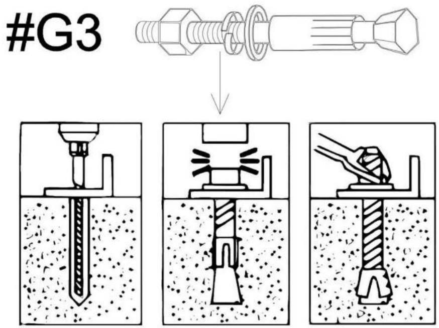

Technical Support and E-Warranty Certificate
www.vevor.com/support
CARPORT INSTALLATION INSTRUCTION
Modelo : KD - TPQC -007-20x24 pies
natural_image
Architectural line drawing of a two-story building with hatched walls and arched entrance (no text or symbols)- Have at least two adults during installation. Readall instructions carefully and follow it accordingly. Failure to do so may result to injury or damage to the carport.
- Never set-up the product in rainy, windy or stormy conditions, especially lighting storms.
- Keep your carport off of thesteep sloppes and inclination.
- After installation, the carport should be anchored to prevent damage and possible injury. It is the user's responsibility to properly anchor the product.
- Aleays inspect the carport and each part before use. Make sure that everything isthighely secured. Replace any worn, defective missing parts.
- For abetter installation and use experience, it is recommended to bring your own ladder, scissors, wlect-ic drill and glass glue.
natural_image
Illustration of a wooden ladder with four yellow steps (no text or symbols)Escalera

natural_image
Line drawing of a pair of scissors (no text or symbols)Tijeras

natural_image
Simple line drawing of a drill bit (no text or symbols)taladro eléctrico
PACKAGE CONTENTS
This carport is packed in 5 boxes. Before the installation, please check all the parts according to the part list. If there is any part missing or defective, please contact us immediately to get replacement parts.
| Part No. | Part Name | Drawing | Qty |
| #1 | Side pole 1 | | 10 PCS |
| #2 | Side pole 2 | | 5 PCS |
| #3 | Straight peak pole | | 12 PCS |
| #4 | Leg pole | | 12 PCS |
| #5 | Top Reinforcing pole | | 18 PCS |
| #6 | Ground bar 1 | | 8 PCS |
| #6a | Ground bar 2 | | 2 PCS |
| #7 | Connector | | 18 PCS |
| #8 | Ground Reinforcing pole | | 4 PCS |
| #9 | Side-side defense pole | | 10 PCS |
| #10 | Side plate 1 | | 3 PCS |
| #11 | Side plate 2 | | 4 PCS |
| #R | Roof cover | | 85 PCS |
| #G1 | M5X20 Self-Tapping screws | | 322 PCS |
| #G1a | M5X25 Self-Tapping screws | | 24 PCS |
| #G2 | Socket head bolt | | 314 PCS |
| #G3 | Expansion screws | | 26 PCS |
| #G4 | Socket head bolt & Nut | | 38 PCS |
| #L | Gloves | | 2 pairs |
| #Y1 | Waterproof tape | | 8 PCS |
| #Y2 | Anti-cut tape | | 20 M |
| #Y3 | Enclosure | | 5 PCS |
| #Y4 | Beads of rope | | 60 PCS |
STEP 1: Assemble the Top Frame
| #3 | | X12 |
| #5 | | X6 |
| #7 | | X18 |
| #G2 | X120 |
Notice:
The linking screws in this step are all: Socket Head Bolt (#G2)

flowchart
graph TD
    A["#3"] --> B["#5"]
    B --> C["#7"]
    C --> D["#3"]
    D --> E["#7"]
    F["#2"] --> G["#G2"]
    G --> H["#3"]
    H --> I["#7"]
    style A fill:#f9f,stroke:#333
    style B fill:#f9f,stroke:#333
    style C fill:#f9f,stroke:#333
    style D fill:#f9f,stroke:#333
    style E fill:#f9f,stroke:#333
    style F fill:#f9f,stroke:#333
    style G fill:#f9f,stroke:#333
    style H fill:#f9f,stroke:#333
    style I fill:#f9f,stroke:#333
STEP 2:
| #1 | X10 | |
| #2 | X5 | |
| #10 | X3 | |
| #11 | X4 | |
| #G4 | X36 |
Notice:
The linking screws in this step are all: Socket Head Bolt (#G4)
STEP 3: Install the Top Roof
Install all the Roof Cover (#R) to the top frame. The linking screws in this step are all:Self-Tapping Screws (#G1), as shown in the picture.
Notice:
- The meaning of different coloerd holes in the Roof Cover(#R);
● Blue hole:no screws here right now.
○ Black hole: nonal installation
1) Starting from the top middle of room 1 to room 5, install the first row of Roof Covers(#R).


When installing the first piece of roof covering, place the middle slot of the tile at the gasket #10 bump for easy reinforcement with screws
| #R | | X1 |
| #Y1 | | X8 |
| #G1 | | X2 |
2) When installing each Roof Cover (#R), you need to use Waterproof Tape (#Y1) as shown in the picture.

natural_image
Technical line drawing of a multi-tiered structural frame structure with no text or symbols
STEP 4:
Notice:
- Make sure that the screw holes are aligned, and then press the Waterproof Tape (#Y1)
- Make sure there are no gaps between the two roof covers to prevent water leakage
3.1) The second Roof Cover (#R) needs to be placed on the first Roof Cover (#R)
| #R | | X4 |
| #Y1 | | |
| #G1 | | X10 |
3.2) Follow the previous steps and continue to install the remaining Roof Cover (#R) in the middle row.

natural_image
Technical line drawing of a structural frame with vertical supports and a central vertical component, no text or symbols present.

natural_image
Technical line drawing of a vertical structural frame with horizontal beams and supports (no text or symbols)
natural_image
Structural diagram of a multi-story building frame with horizontal beams and vertical supports, enclosed in an oval boundary (no text or symbols)4.1) After installing the middle row, continue to install the 4 rows on the right. Each newly installed Roof Cover (#R) in a row needs to be placed below the Roof Cover (#R) in the previous row, as shown in the picture.

| #R | X5 | |
| #Y1 | ||
| #G1 | X18 |
4.2) Same as the previous step, after pasting the Waterproof Tape(#Y1) of RoofCovers(#R), install the next Roof Covers(#R).

natural_image
Technical line drawing of a structural frame with vertical supports and a curved dashed line indicating rotation or alignment (no text or symbols)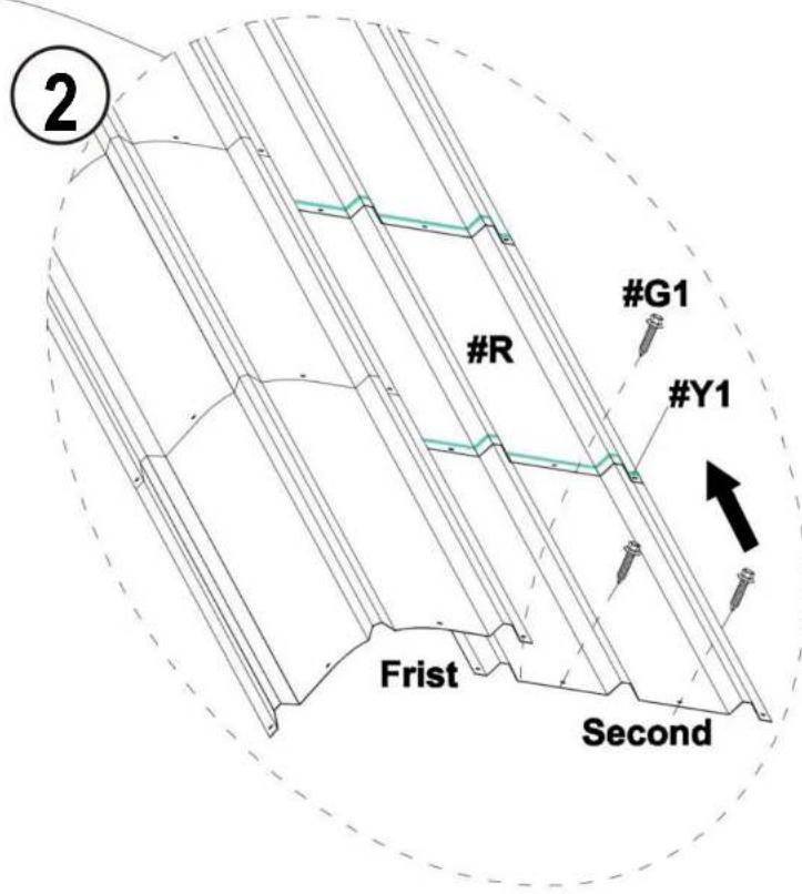
4.3) Follow the previous steps and continue to install the Roof Cover (#R) in the remaining 6 rows on the right.
| #R | X30 | |
| #Y1 | ||
| #G1 | X108 |

natural_image
Technical line drawing of a multi-tiered metal shelving unit (no text or symbols)
5.2) Same as the installation steps for the 6 rows on the right, please complete the installation of Roof Cover(#R) of the 7 rows on the left.
| #R | | X35 |
| #Y1 | | |
| #G1 | | X126 |

natural_image
Architectural line drawing of a three-tiered structural frame structure (no text or symbols)
STEP 5: Connect Legs
1) Install Leg Pole(#4) and Top Reinforcing pole(#5)
to the Connector(#7).
2) The linking screws in this step are all: Hex Head Cap Bolt (#G2).
| #4 | X12 | |
| #5 | X12 | |
| #G2 | X96 |
STEP 6: Reinforce the Frame
1) Connect all the Leg Pole(#4) to Ground bar 1(#6) and Ground bar 2(#6a) 2) The linking screws in this step are all: Hex Head Cap Bolt (#G2) and Expansion screws (#G3).
| #6 | X8 | |
| #6a | X2 | |
| #8 | X4 | |
| #G2 | X88 |

natural_image
Architectural line drawing of a large arched structure with vertical supports and horizontal beams (no text or symbols)
STEP 7: Reinforce the Frame
Secure 5 wall cloths (#Y3) to the frame with rope beads (#Y4)
| #Y3 | X5 | |
| #Y4 | X60 |

STEP 8: Install the Side Roof
After installing the Leg Pole(#4), continue to install the Roof Cover (#R) in the 4 rows on the left and right sides.
1) First install the Roof Cover (#R) in the left row, as shown in the picture.
| #R | X5 | |
| #Y1 | ||
| #G1 | X24 |

Notice:
- Make sure that the screw holes are aligned, and then press the Waterproof Tape (#Y1)
- Make sure there are no gaps between the two roof covers to prevent water leakage
- The second Roof Cover (#R) needs to be placed on the first Roof Cover (#R)

2) Follow the previous steps and continue to install the Roof Cover (#R) in the remaining 1 rows on the right.

natural_image
Isometric line drawing of a steel truss structure with grid pattern (no text or symbols)| #R | | X5 |
| #Y1 | | |
| #G1 | | X24 |
| #Y2 | |
STEP9: Install the Anti-cut Tape (#Y2)
1) Wrap the Anti-cut Tape (#Y2) around the outer edge of the Roof Coveers(#R).

natural_image
Line drawing of a steel-framed industrial structure with grid pattern (no text or symbols)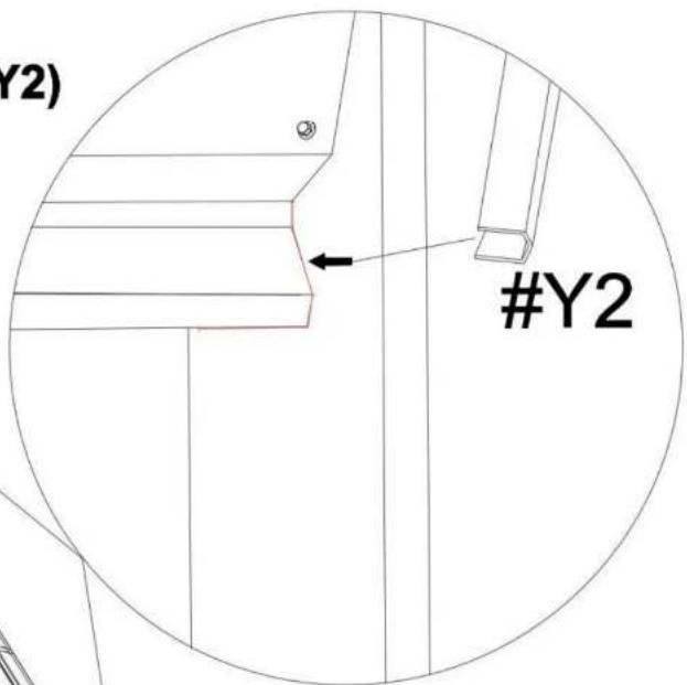
Notice:
Be careful not to start from the 4 corners when wrapping the tape. Right angles are sharp and need to be avoided.
STEP10: Side-side defense pole
After installing I the Roof Cover (#R).on the left and right sides. 1) Install the Side-side defense pole(#9) in the left and right row, as shown in the picture.
| #9 | X10 | |
| #G1a | X20 |

STEP11 : Anchor the Carport
Install the Anchor the Carport on the ground.
Notice:
The linking screws in this step are all: Expansion screws
| #G3 | X24 |

natural_image
Architectural line drawing of a large industrial structure with hatched walls and support beams (no text or symbols)

www.vevor.com/support
VEVOR
Technical Support and E-Warranty Certificate www.vevor.com/support
CARPORT INSTALLATION INSTRUCTION
Modell : KD - TPQC -007-20x24 fot

natural_image
Architectural line drawing of a two-story building with hatched walls and arched entrance (no text or symbols)- Have at least two adults during installation. Readall instructions carefully and follow it accordingly. Failure to do so may result to injury or damage to the carport.
- Never set-up the product in rainy, windy or stormy conditions, especially lighting storms.
- Keep your carport off of thesteep sloppes and inclination.
- After installation, the carport should be anchored to prevent damage and possible injury. It is the user's responsibility to properly anchor the product.
- Aleays inspect the carport and each part before use. Make sure that everything isthighely secured. Replace any worn, defective missing parts.
- For abetter installation and use experience, it is recommended to bring your own ladder, scissors, wlectric drill and glass glue.
SÄKERHET INSTRUKTIONER
WARNING :
natural_image
Illustration of a wooden ladder with yellow shelves (no text or symbols)Stege
natural_image
Line drawing of a pair of scissors (no text or symbols)Sax

natural_image
Simple line drawing of a drill bit (no text or symbols)Elektrisk borr
PACKAGE CONTENTS
This carport is packed in 5 boxes. Before the installation, please check all the parts according to the part list. If there is any part missing or defective, please contact us immediately to get replacement parts.
| Part No. | Part Name | Drawing | Qty |
| #1 | Side pole 1 | | 10PCS |
| #2 | Side pole 2 | | 5 PCS |
| #3 | Straight peak pole | | 12 PCS |
| #4 | Leg pole | | 12 PCS |
| #5 | Top Reinforcing pole | | 18 PCS |
| #6 | Ground bar 1 | | 8 PCS |
| #6a | Ground bar 2 | | 2 PCS |
| #7 | Connector | | 18 PCS |
| #8 | Ground Reinforcing pole | | 4 PCS |
| #9 | Side-side defense pole | | 10 PCS |
| #10 | Side plate 1 | | 3 PCS |
| #11 | Side plate 2 | | 4 PCS |
| #R | Roof cover | | 85 PCS |
| #G1 | M5X20 Self-Tapping screws | | 322PCS |
| #G1a | M5X25 Self-Tapping screws | | 24 PCS |
| #G2 | Socket head bolt | | 314 PCS |
| #G3 | Expansion screws | | 26 PCS |
| #G4 | Socket head bolt & Nut | | 38 PCS |
| #L | Gloves | | 2 pairs |
| #Y1 | Waterproof tape | | 8 PCS |
| #Y2 | Anti-cut tape | | 20 M |
| #Y3 | Enclosure | | 5 PCS |
| #Y4 | Beads of rope | | 60 PCS |
STEP 1: Assemble the Top Frame
| #3 | | X12 |
| #5 | | X6 |
| #7 | | X18 |
| #G2 | X120 |
Notice:
The linking screws in this step are all: Socket Head Bolt (#G2)

flowchart
graph TD
    A["#3"] --> B["#5"]
    B --> C["#7"]
    C --> D["#3"]
    D --> E["#7"]
    F["#2"] --> G["#G2"]
    G --> H["#3"]
    H --> I["#7"]
    style A fill:#f9f,stroke:#333
    style B fill:#f9f,stroke:#333
    style C fill:#f9f,stroke:#333
    style D fill:#f9f,stroke:#333
    style E fill:#f9f,stroke:#333
    style F fill:#f9f,stroke:#333
    style G fill:#f9f,stroke:#333
    style H fill:#f9f,stroke:#333
    style I fill:#f9f,stroke:#333
STEP 2:
| #1 | X10 | |
| #2 | X5 | |
| #10 | X3 | |
| #11 | X4 | |
| #G4 | X36 |
Notice:
The linking screws in this step are all: Socket Head Bolt (#G4)


STEP 3: Install the Top Roof
Install all the Roof Cover (#R) to the top frame. The linking screws in this step are all:Self-Tapping Screws (#G1), as shown in the picture.
Notice:
- The meaning of different coloerd holes in the Roof Cover(#R);
● Blue hole:no screws here right now.
○ Black hole: nonal installation
1) Starting from the top middle of room 1 to room 5, install the first row of Roof Covers(#R).


When installing the first piece of roof covering, place the middle slot of the tile at the gasket #10 bump for easy reinforcement with screws
| #R | | X1 |
| #Y1 |  | X8 |
| #G1 | | X2 |
2) When installing each Roof Cover (#R), you need to use Waterproof Tape (#Y1) as shown in the picture.

natural_image
Technical line drawing of a multi-tiered structural frame structure with no text or symbols
STEP 4:
Notice:
- Make sure that the screw holes are aligned, and then press the Waterproof Tape (#Y1)
- Make sure there are no gaps between the two roof covers to prevent water leakage
3.1) The second Roof Cover (#R) needs to be placed on the first Roof Cover (#R)
| #R | | X4 |
| #Y1 | | |
| #G1 | | X10 |
3.2) Follow the previous steps and continue to install the remaining Roof Cover (#R) in the middle row.
natural_image
Technical line drawing of a structural frame with vertical supports and a central vertical component, no text or symbols present.

natural_image
Technical line drawing of a vertical structural frame with horizontal beams and supports (no text or symbols)
natural_image
Structural diagram of a multi-story building frame with horizontal beams and vertical supports, enclosed in an oval boundary (no text or symbols)4.1) After installing the middle row, continue to install the 4 rows on the right. Each newly installed Roof Cover (#R) in a row needs to be placed below the Roof Cover (#R) in the previous row, as shown in the picture.

| #R | X5 | |
| #Y1 | ||
| #G1 | X18 |
4.2) Same as the previous step, after pasting the Waterproof Tape(#Y1) of RoofCovers(#R), install the next Roof Covers(#R).

natural_image
Technical line drawing of a structural frame with vertical supports and a curved dashed line indicating rotation or alignment (no text or symbols)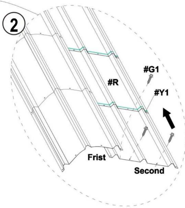
4.3) Follow the previous steps and continue to install the Roof Cover (#R) in the remaining 6 rows on the right.
| #R | X30 | |
| #Y1 | ||
| #G1 | X108 |

natural_image
Technical line drawing of a multi-tiered metal shelving unit (no text or symbols)
5.2) Same as the installation steps for the 6 rows on the right, please complete the installation of Roof Cover(#R) of the 7 rows on the left.
| #R | | X35 |
| #Y1 | | |
| #G1 | | X126 |

natural_image
Architectural line drawing of a three-tiered structural frame structure (no text or symbols)
STEP 5: Connect Legs
1) Install Leg Pole(#4) and Top Reinforcing pole(#5)
to the Connector(#7).
2) The linking screws in this step are all: Hex Head Cap Bolt (#G2).

| #4 | X12 | |
| #5 | X12 | |
| #G2 | X96 |
STEP 6: Reinforce the Frame
1) Connect all the Leg Pole(#4) to Ground bar 1(#6) and Ground bar 2(#6a) 2) The linking screws in this step are all: Hex Head Cap Bolt (#G2) and Expansion screws (#G3).
| #6 | X8 | |
| #6a | X2 | |
| #8 | X4 | |
| #G2 | X88 |

natural_image
Architectural line drawing of a large arched structure with vertical supports and horizontal beams (no text or symbols)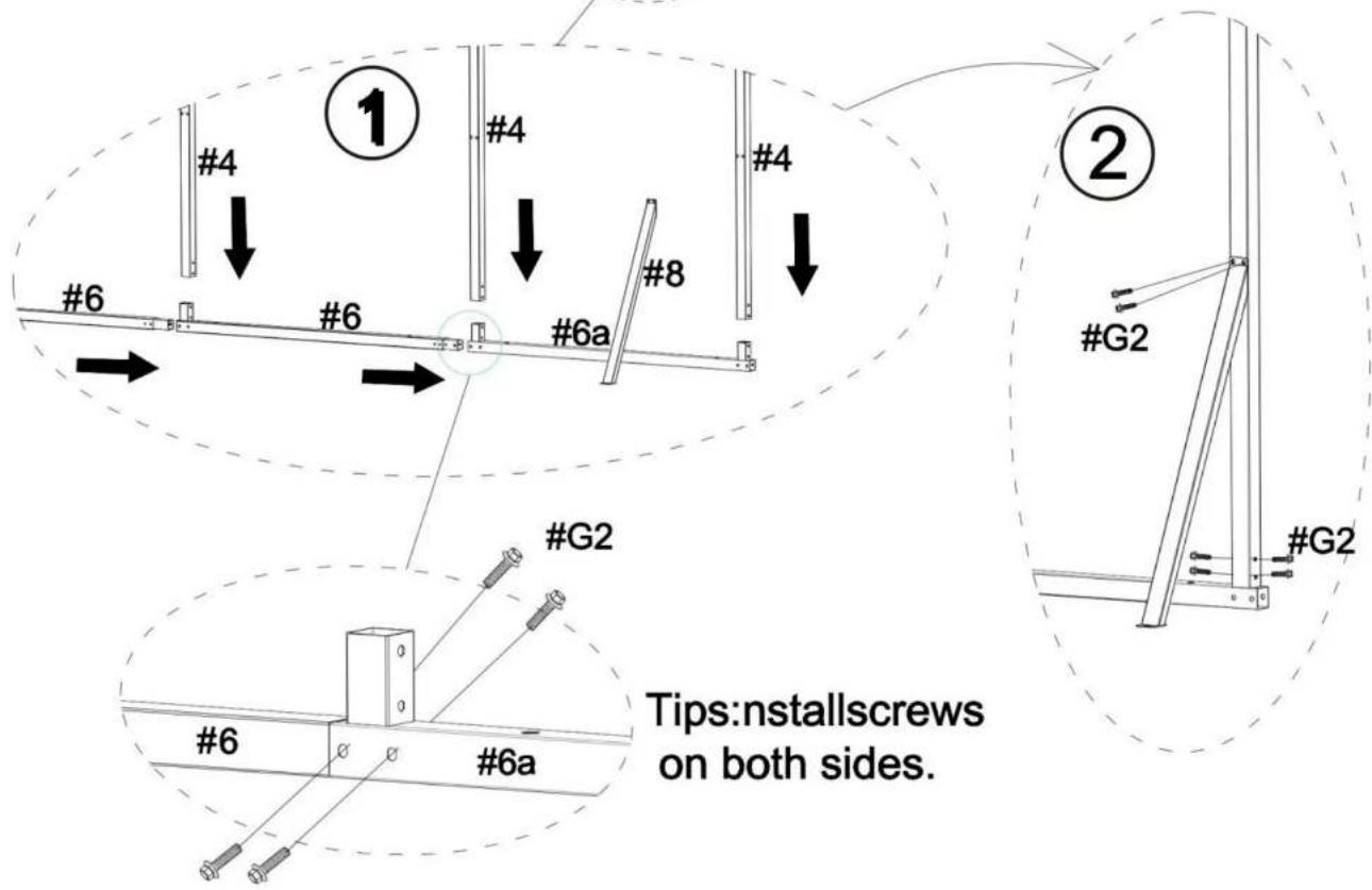
STEP 7: Reinforce the Frame
Secure 5 wall cloths (#Y3) to the frame with rope beads (#Y4)
| #Y3 | X5 | |
| #Y4 | X60 |

STEP 8: Install the Side Roof
After installing the Leg Pole(#4), continue to install the Roof Cover (#R) in the 4 rows on the left and right sides.
1) First install the Roof Cover (#R) in the left row, as shown in the picture.
| #R | X5 | |
| #Y1 | ||
| #G1 | X24 |

Notice:
- Make sure that the screw holes are aligned, and then press the Waterproof Tape (#Y1)
- Make sure there are no gaps between the two roof covers to prevent water leakage
- The second Roof Cover (#R) needs to be placed on the first Roof Cover (#R)

2) Follow the previous steps and continue to install the Roof Cover (#R) in the remaining 1 rows on the right.
natural_image
Isometric line drawing of a steel truss structure with grid pattern (no text or symbols)| #R | | X5 |
| #Y1 | | |
| #G1 | | X24 |
| #Y2 | |
STEP9: Install the Anti-cut Tape (#Y2)
1) Wrap the Anti-cut Tape (#Y2) around the outer edge of the Roof Coveers(#R).

natural_image
Line drawing of a steel-framed industrial structure with grid pattern (no text or symbols)
Notice:
Be careful not to start from the 4 corners when wrapping the tape. Right angles are sharp and need to be avoided.
STEP10: Side-side defense pole
After installing I the Roof Cover (#R).on the left and right sides. 1) Install the Side-side defense pole(#9) in the left and right row, as shown in the picture.
| #9 | X10 | |
| #G1a | X20 |

STEP11 : Anchor the Carport
Install the Anchor the Carport on the ground.
Notice:
The linking screws in this step are all: Expansion screws
| #G3 | X24 |

natural_image
Architectural line drawing of a large industrial structure with hatched walls and support beams (no text or symbols)