GZB88096 - Power tool accessory Vevor - Free user manual and instructions
Find the device manual for free GZB88096 Vevor in PDF.

User questions about GZB88096 Vevor
0 question about this device. Answer the ones you know or ask your own.
Ask a new question about this device
Download the instructions for your Power tool accessory in PDF format for free! Find your manual GZB88096 - Vevor and take your electronic device back in hand. On this page are published all the documents necessary for the use of your device. GZB88096 by Vevor.
USER MANUAL GZB88096 Vevor
Technical Support and E-Warranty Certificate
www.vevor.com/support
MOBILE BASE
MODEL: GZB88096
We continue to be committed to provide you tools with competitive price. "Save Half", "Half Price" or any other similar expressions used by us only represent of savings you might benefit from buying certain tools with us compared top brands and does not necessarily mean to cover all categories of tools offered are kindly reminded to verify carefully when you are placing an order with us actually saving half in comparison with the top major brands.
MODEL: GZB88096
natural_image
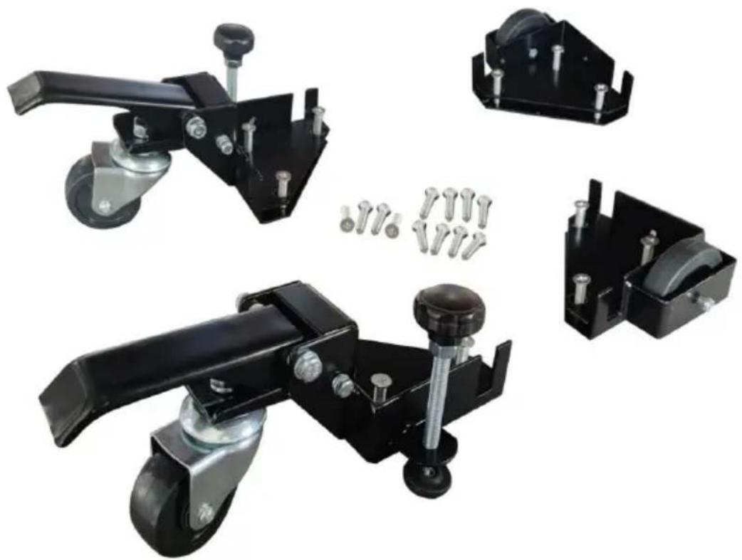
Product assembly of black mechanical clamps with metal hardware and bolted components (no text or symbols visible)Photo for reference
NEED HELP? CONTACT US!
Have product questions? Need technical support? Please feel fr contact us:
Technical Support and E-Warranty Certificate www.vevor.com/support
This is the original instruction, please read all manual instruction carefully before operating. VEVOR reserves a clear interpretation user manual. The appearance of the product shall be subject to product you received. Please forgive us that we won't inform you there are any technology or software updates on our product.
SAFETY INSTRUCTIONS

WARNING: Read and understand this manual before assembling, installing, operating, or servicing this product.
Failure to follow these warnings and instructions can cau
death, personal injury or damage to valuable property.
- While assembling and using this product, keep the work area clean well-lighted, and keep spectators and children out of the work area.
- Wear ANSI-approved safety goggles and heavy-duty work gloves during use.

Warning- Be sure to wear eye protectors when usi product.

Warning- Be sure to wear gloves when using this
- Please do not put it near flammable materials.
- It is forbidden to carry people under any condition.
- This product cannot be used to go up or down stairs.
- Overload is strictly prohibited.
- Don't move too fast when passing pothole areas.
- Electric tools are required for installation. Please pay attention to s operation.
SAVE THESE INSTRUCTIONS
MODEL AND PARAMETERS
Material: Q235
Product size: Minimum 9.5x9.5 inches
Load capacity: 400 lbs max.
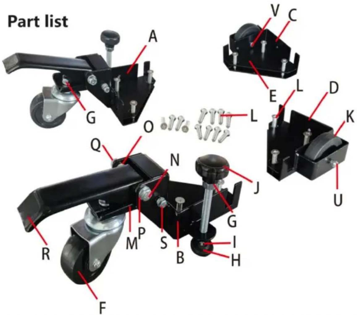
| Parts List | |||||
| S/N | Description | Qty | S/N | Description | Qty |
| A | CORNER, L.H. W/CASTER BRACKET | 1 | L | M8-30 MACHINE SCREW | 12 |
| B | CORNER, R.H. W/CASTER BRACKET | 1 | L | M8-40 MACHINE SCREW | 12 |
| C | CORNER, L.H. W/WHEEL HOUSING | 1 | M | SWIVEL PLATE | 2 |
| D | CORNER, R.H. W/WHEEL HOUSING | 1 | N | 8x75 Carriage Bolt | 2 |
| E | BOLT PLATE | 4 | O | NYLON Foot LEVER BUSHING | 4 |
| F | 3" SWIVEL CASTER WHEEL | 2 | P | M8 LOCK WASHER | 2 |
| G | M10 NUTS, FLANGED/SERRATED | 4 | Q | M-8 NUT SELF-LOCKING | 2 |
| ROUND FEET | 2 | FOOT LEVER | 2 | ||
| M10 JAM NUT | 2 | 6 x 75 CARRIAGE BOLT | 2 | ||
| LONG POLE HANDLE | 2 | M6 NYLON WHEELBUSHING | 4 | ||
| 3" WHEEL | 2 | M6 NUT, SELF-LOCKING | 4 | ||
| 6x 47-10 MACHINESCREW, AXLE | 2 | ||||
Safety Instructions for Mobile Bases
- Be careful when moving to limit any finger pinch points.
- Place base on a level surface and adjust levelers before placing the machi position. This should keep the machine from rocking, while testing it for stabilit
3.3 Test the stability in both the up (on the casters) and the down positions.
Exercise caution when testing the stability of top-heavy machines (drill presses band saws, etc.).
- Unplug any power tool before moving or repositioning your tool.
- Always test your set-up for stability and safety after repositioning.
- Care should be taken when planning the orientation of the machine onto the Universal Mobile Base. Transfer the weight off of the levelers to the casters result in the machine tilting1/2" toward the fixed wheels. When positioning top-heavy tools such as a drill press or bandsaw, take advantage of the cer gravity, and position so that it will remain stable while on casters.
- Never use your machine without engaging the floor locks and foot locks. lower the machine onto the non-skid levelers before operating.
- When moving, always push the base, not the machine.
ASSEMBLY Instructions
- Unpack and identify all components and hardware. Make sure there are no missing parts and that there is no shipping damage.
Note: Read instructions thoroughly before proceeding.
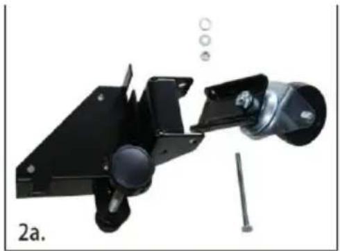
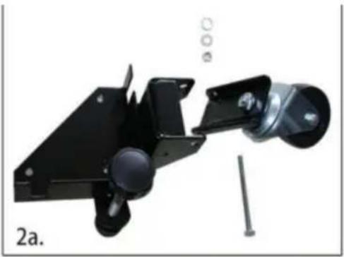
- Assemble the front corners:
a. Thread the rubber glide foot into the bracket, then thread the jam nut onto the top
b. Attach the wheel to the swivel plate.
c. Install the swivel plate using the M8-75 carriage bolt, lock washer, and nut. Tighten.
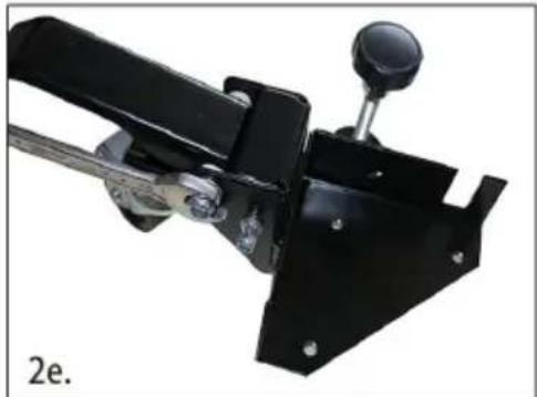
d. Install the foot lever using the M8-75 carriage bolt, nylon washers, lock washer, and nut.
natural_image
Mechanical assembly with black frame, spring, and screw (no visible text or symbols)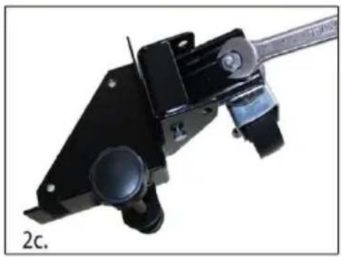
natural_image
Mechanical component with black frame and lever, labeled '2c.' (no text or symbols on the object itself)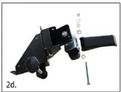
natural_image
Mechanical component with attached lever and screw assembly (no visible text or symbols)2.
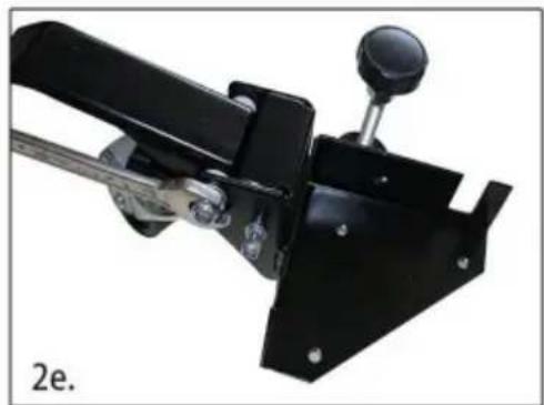
e. Repeat this process for the other swivel bracket
- Assemble the back corners, to the right are the components you will need:
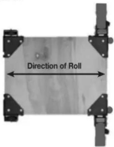
a. Install the back wheel using the M6×47-10 axle bolt, nylon wheel bushing, and M6 lock nut. - Carefully measure the footprint of your machine (or whatever you are mobilizing) and add about 1" to the dimension. (1" allows clearance for the fasteners).
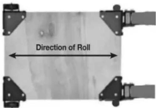
- Review the assembly examples shown below to help you determine the fixed wheel, caster and leveler placement. As these are examples only, you must determine what best suits your particular machine's requirements for stability.
Tighten all hardware securely
natural_image
Mechanical clamp device with black frame and metal lever (no visible text or symbols)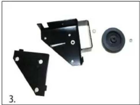
natural_image
Disassembled black metal bracket components including a circular component and two separate views (no text or symbols visible)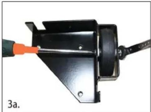
natural_image
Close-up of a black metal bracket being adjusted with a tool, labeled '3a.' (no text or symbols on the object itself)Assembly Examples
Be sure to follow Safety and Assembly Instructions. Keep in mind the actual operation of your machine and the effect it has on overall stability.

A long, narrow base, such as on a jointer, would benefit from this arrangement. Most machines may be arranged to the convenience of the user.
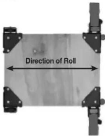
A short, narrow base, such as found on a drill press or bandsaw, may benefit from this arrangement. Due to swivel rotation, base may sit out of level. Rotate swivel wheel away from base to correct.
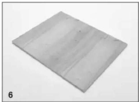
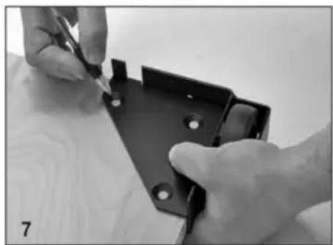
- Cut the plywood you are using down to size.
natural_image
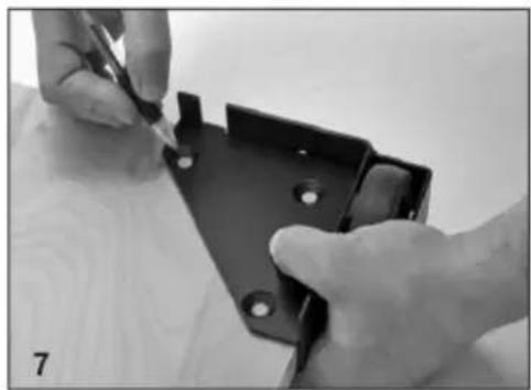
Square gray metal plate with horizontal grooves, labeled '6' in corner (no other text or symbols)- You will now need to attach the corners to the plywood, begin by marking the holes using the corner plates as your template.
natural_image
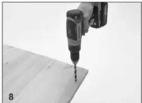
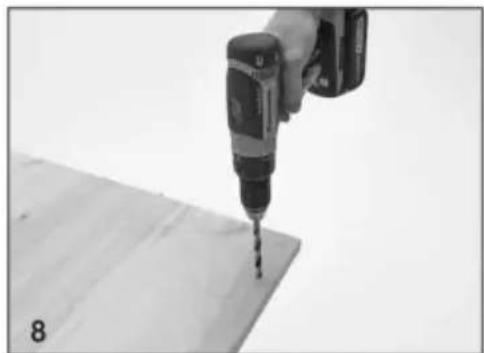
Close-up of hands using a tool to adjust or install a black metal bracket (no visible text or symbols)- Drill the holes using a 12 " drill bit, it is a good idea to check that the holes are lined up to the plate before drilling each hole.
natural_image
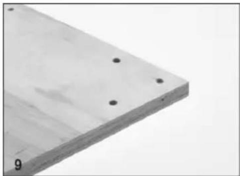
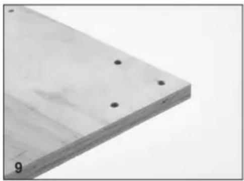
Hand using a drill pen to apply material on a wooden surface (no text or symbols visible)- Each corner should now look like this.
natural_image
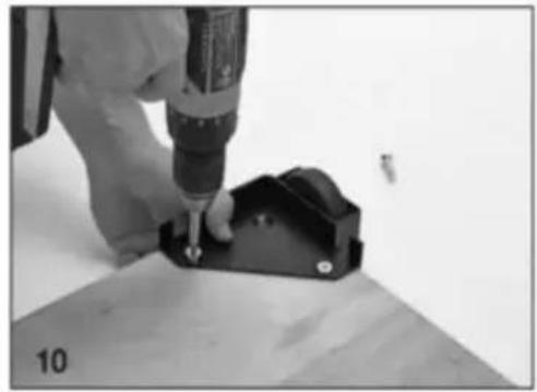
Close-up of a wooden plank with four small holes, labeled '9' in the corner (no other text or symbols)- Attach the corners in the correct positions using the Philips screwdriver, do not tighten the bolts until all three machine screws are partially threaded into the bottom plate.
natural_image
Close-up of a hand using a drill bit to adjust or install a black mechanical component (no visible text or symbols)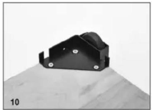
natural_image
Black metal bracket with mounting holes on a textured surface (no text or symbols visible)- Congratulations! You have successfully completed assembly of the GZB88096 mobile base.
MAINTENANCE
- Avoid prolonged exposure to the sun to avoid aging.
- Inspect accessories for wear, cracks and other damage before use, replace defective accessories immediately.
Manufacturer: Shanghaimuxinmuyeyouxiangongsi
Address: Shuangchenglu 803nong11hao1602A-1609shi, baoshanqu, shanghai 200000 CN.
Imported to AUS: SIHAO PTY LTD, 1 ROKEVA STREETEASTWOOD NS 2122 Australia
Imported to USA: Sanven Technology Ltd., Suite 250, 9166 Anaheim Pla Rancho Cucamonga, CA 91730
| EC | REP |
E-CrossStu GmbH
Mainzer Landstr.69, 60329 Frankfurt am Ma
| UK | REP |
YH CONSULTING LIMITED.
C/O YH Consulting Limited Office 147, Centurion H
London Road, Staines-upon-Thames, Surrey, TW18 4
VEVOR®
TOUGH TOOLS, HALF PRICE
Technical Support and E-Warranty Certificate www.vevor.com/support
VEVOR®
TOUGH TOOLS, HALF PRICE
natural_image
Four black mechanical components with various mounting holes and screws, shown from different angles (no text or symbols visible)| Liste des pièces | |||||
| Description du numéro de série | Qté | S/N | Description | Qté | |
| COIN, GAUCHE AVEC ROULETTE SUPPORT | 1 | VIS | MÉCANIQUE M8-30 12 | ||
| COIN DROIT AVEC ROULETTES SUPPORT | 1 | VIS | MÉCANIQUE M8-40 12 | ||
| COIN, LH AVEC ROUE LOGEMENT | 1 | PLAQUE PIVOTANTE | 2 | ||
| COIN DROIT AVEC ROUE LOGEMENT | 1 | boulon | de carrosserie 8x75 | 2 | |
| PLAQUE DE BOULON | 4 | LEVIER À PIED EN NYLON BAGUE | 4 | ||
| ROULETTES PIVOTANTES DE 3" | RONDELLE DE BLOCAGE 2 M8 | 2 | |||
| ÉCROUS M10, BRIDE/DENTELÉ | 4 | ECROU M-8 AUTOBLOQUANT | 2 | ||
| PIEDS RONDS | 2 | LEVIER AU PIED | 2 | |
| CONTRE-ÉCROU M10 | BOULON | DE CHARIOT 2 6 x 75 | 2 | |
| POIGNÉE LONGUE | 2 | ROUE EN NYLON M6BAGUE | 4 | |
| ROUE 3" | 2 | ÉCROU M6 AUTOBLOQUANT | 4 | |
| 6x 47-10 MACHINESVIS D'AXE | 2 | |||
- Unpack and identify all components and hardware. Make sure there are no missing parts and that there is no shipping damage.
Note: Read instructions thoroughly before proceeding.
- Assemble the front corners:
a. Thread the rubber glide foot into the bracket, then thread the jam nut onto the top
b. Attach the wheel to the swivel plate.
c. Install the swivel plate using the M8-75 carriage bolt, lock washer, and nut. Tighten.
d. Install the foot lever using the M8-75 carriage bolt, nylon washers, lock washer, and nut.

natural_image
Mechanical assembly with black frame and mechanical component, labeled '2a.' (no text or symbols on the diagram itself)
natural_image
Mechanical component with black frame and metallic rod, labeled '2c.' (no text or symbols on the object itself)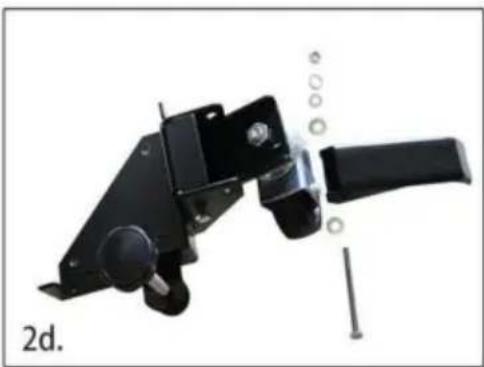
natural_image
Mechanical component with attached lever and screw assembly (no visible text or symbols)2.
e. Repeat this process for the other swivel bracket
- Assemble the back corners, to the right are the components you will need:
a. Install the back wheel using the M6×47-10 axle bolt, nylon wheel bushing, and M6 lock nut.
-
Carefully measure the footprint of your machine (or whatever you are mobilizing) and add about 1" to the dimension. (1" allows clearance for the fasteners).
-
Review the assembly examples shown below to help you determine the fixed wheel, caster and leveler placement. As these are examples only, you must determine what best suits your particular machine's requirements for stability.
Tighten all hardware securely

natural_image
Mechanical clamp device with black frame and metal handle (no visible text or symbols)
natural_image
Disassembled metal bracket components including a circular component and two separate views (no text or symbols visible)
natural_image
Close-up of a black metal mechanical component being adjusted with a tool, labeled '3a.' (no text or symbols on the object itself)Assembly Examples
Be sure to follow Safety and Assembly Instructions. Keep in mind the actual operation of your machine and the effect it has on overall stability.

A long, narrow base, such as on a jointer, would benefit from this arrangement. Most machines may be arranged to the convenience of the user.

A short, narrow base, such as found on a drill press or bandsaw, may benefit from this arrangement. Due to swivel rotation, base may sit out of level. Rotate swivel wheel away from base to correct.
- Cut the plywood you are using down to size.

natural_image
Square metal plate with horizontal grooves, labeled '6' at bottom left (no other text or symbols)- You will now need to attach the corners to the plywood, begin by marking the holes using the corner plates as your template.

natural_image
Close-up of hands installing a black metal bracket with a tool, placed on a wooden surface (no text or symbols visible)- Drill the holes using a 12 " drill bit, it is a good idea to check that the holes are lined up to the plate before drilling each hole.

natural_image
Close-up of a hand using a drill pen to draw a screw on a wooden surface (no text or symbols visible)- Each corner should now look like this.

natural_image
Close-up of a wooden plank with two small holes, labeled '9' in the corner (no other text or symbols)Machine Translated by Google
- Attach the corners in the correct positions using the Philips screwdriver, do not tighten the bolts until all three machine screws are partially threaded into the bottom plate.

natural_image
Close-up of a hand using a drill bit to adjust or install a mechanical component (no visible text or symbols)
natural_image
Black metal bracket with mounting holes on a wooden surface (no text or symbols visible)- Congratulations! You have successfully completed assembly of the GZB88096 mobile base.
ENTRETIEN
C/O YH Consulting Limited Bureau 147, Centurion House, London Road, Staines-upon-Thames, Surrey, TW18 4AX
VEVOR®
TOUGH TOOLS, HALF PRICE
www.vevor.com/support
MOBILE BASIS
MODELL: GZB88096
natural_image
Product assembly of black mechanical clamps with metal hardware and bolted components (no text or symbols visible)Foto als Referenz
- Unpack and identify all components and hardware. Make sure there are no missing parts and that there is no shipping damage.
Note: Read instructions thoroughly before proceeding.
- Assemble the front corners:
a. Thread the rubber glide foot into the bracket, then thread the jam nut onto the top
b. Attach the wheel to the swivel plate.
c. Install the swivel plate using the M8-75 carriage bolt, lock washer, and nut. Tighten.
d. Install the foot lever using the M8-75 carriage bolt, nylon washers, lock washer, and nut.
natural_image
Mechanical device with black frame and attached sensor or camera component, labeled '2a.' (no text or symbols on the device itself)
natural_image
Mechanical component with black frame and metallic rod, labeled '2c.' (no text or symbols on the object itself)
natural_image
Mechanical component with attached lever and screw assembly (no visible text or symbols)2.
e. Repeat this process for the other swivel bracket
- Assemble the back corners, to the right are the components you will need:
a. Install the back wheel using the M6×47-10 axle bolt, nylon wheel bushing, and M6 lock nut.
-
Carefully measure the footprint of your machine (or whatever you are mobilizing) and add about 1" to the dimension. (1" allows clearance for the fasteners).
-
Review the assembly examples shown below to help you determine the fixed wheel, caster and leveler placement. As these are examples only, you must determine what best suits your particular machine's requirements for stability.
Tighten all hardware securely

natural_image
Mechanical clamp device with black frame and metal handle (no visible text or symbols)
natural_image
Disassembled metal bracket components including a circular component and two separate views (no text or symbols visible)
natural_image
Close-up of a black metal bracket being adjusted with a tool, no visible text or symbolsAssembly Examples
Be sure to follow Safety and Assembly Instructions. Keep in mind the actual operation of your machine and the effect it has on overall stability.

A long, narrow base, such as on a jointer, would benefit from this arrangement. Most machines may be arranged to the convenience of the user.

A short, narrow base, such as found on a drill press or bandsaw, may benefit from this arrangement. Due to swivel rotation, base may sit out of level. Rotate swivel wheel away from base to correct.
- Cut the plywood you are using down to size.

natural_image
Square metal plate with horizontal grooves, labeled '6' at bottom left (no other text or symbols)- You will now need to attach the corners to the plywood, begin by marking the holes using the corner plates as your template.

natural_image
Close-up of hands installing a black metal bracket with a tool, placed on a wooden surface (no text or symbols visible)- Drill the holes using a 12 " drill bit, it is a good idea to check that the holes are lined up to the plate before drilling each hole.

natural_image
Close-up of a hand using a drill pen to draw a screw on a wooden surface (no text or symbols visible)- Each corner should now look like this.

natural_image
Close-up of a wooden plank with two small holes, labeled '9' in the corner (no other text or symbols)Machine Translated by Google
- Attach the corners in the correct positions using the Philips screwdriver, do not tighten the bolts until all three machine screws are partially threaded into the bottom plate.

natural_image
Close-up of a hand using a drill bit to adjust or install a mechanical component (no visible text or symbols)
natural_image
Black metal bracket with mounting holes on a wooden surface (no text or symbols visible)- Congratulations! You have successfully completed assembly of the GZB88096 mobile base.
WARTUNG
C/O YH Consulting Limited Office 147, Centurion House, London Road, Staines-upon-Thames, Surrey, TW18 4AX
VEVOR®
TOUGH TOOLS, HALF PRICE
elettronica www.vevor.com/support
BASE MOBILE
MODELLO: GZB88096
natural_image
Four black mechanical clamping devices with various mounting fixtures and metal fasteners, shown from different angles (no text or symbols visible)| Elenco delle parti | |||||
| Descrizione S/N | Qtà | S/N | Descrizione | Qtà | |
| ÿ | ANGOLO SINISTRO CON RUOTA STAFFA | 1 y | VITE | A MACCHINA M8-30 12 | |
| ÿ | ANGOLO DESTRO CON RUOTA STAFFA | 1 y | VITE | A MACCHINA M8-40 12 | |
| ÿ | ANGOLO SX CON RUOTA ALLOGGIO | 1 y | PIASTRA GIREVOLE | 2 | |
| ÿ | ANGOLO DESTRO CON RUOTA ALLOGGIO | 1 y | Bullone di trasporto 8x75 | 2 | |
| ÿ PIA STRA BULLONE | 4 y | LEVA A PEDALE IN NYLON BOCCOLA | 4 | ||
| ÿ RUOTA GIREVOLE DA 3 " | 2 y | RONDELLA DI SICUREZZA M8 | 2 | ||
| ÿ | DADI M10, FLANGIATO/SEGHETTATO | 4 y | DADO M-8 AUTOBLOCCANTE | 2 | |
| ÿ PIEDI ROTONDO | 2ÿ | LEVA | A PIEDE | 2 | |
| ÿ DADO CONTRASTO M10 | 2ÿ | 6 x 75 | BULLONE TRASPORTO | 2 | |
| ÿ MANICO A PALO LUNGO | 2ÿ | RUOTA IN NYLON M6BOCCOLA | 4 | ||
| ÿ RUOTA DA 3". | 2ÿ | DADO M6, AUTOBLOCCANTE | 4 | ||
| ÿ | 6x MACCHINA 47-10VITE ASSE | 2 | |||
- Unpack and identify all components and hardware. Make sure there are no missing parts and that there is no shipping damage.
Note: Read instructions thoroughly before proceeding.
- Assemble the front corners:
a. Thread the rubber glide foot into the bracket, then thread the jam nut onto the top
b. Attach the wheel to the swivel plate.
c. Install the swivel plate using the M8-75 carriage bolt, lock washer, and nut. Tighten.
d. Install the foot lever using the M8-75 carriage bolt, nylon washers, lock washer, and nut.

natural_image
Mechanical device with black frame and attached sensor or camera component, labeled '2a.' (no text or symbols on the device itself)
natural_image
Mechanical component with black frame and metallic rod, labeled '2c.' (no text or symbols on the object itself)
natural_image
Mechanical component with attached lever and screw assembly (no visible text or symbols)2.
e. Repeat this process for the other swivel bracket
- Assemble the back corners, to the right are the components you will need:
a. Install the back wheel using the M6×47-10 axle bolt, nylon wheel bushing, and M6 lock nut. - Carefully measure the footprint of your machine (or whatever you are mobilizing) and add about 1" to the dimension. (1" allows clearance for the fasteners).
- Review the assembly examples shown below to help you determine the fixed wheel, caster and leveler placement. As these are examples only, you must determine what best suits your particular machine's requirements for stability.
Tighten all hardware securely

natural_image
Mechanical clamp device with black frame and metal handle (no visible text or symbols)
natural_image
Disassembled metal bracket components including a circular component and two separate views (no text or symbols visible)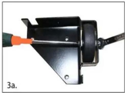
natural_image
Close-up of a black metal bracket being adjusted with a tool, no visible text or symbolsAssembly Examples
Be sure to follow Safety and Assembly Instructions. Keep in mind the actual operation of your machine and the effect it has on overall stability.

A long, narrow base, such as on a jointer, would benefit from this arrangement. Most machines may be arranged to the convenience of the user.

A short, narrow base, such as found on a drill press or bandsaw, may benefit from this arrangement. Due to swivel rotation, base may sit out of level. Rotate swivel wheel away from base to correct.
- Cut the plywood you are using down to size.

natural_image
Square metal plate with horizontal grooves, labeled '6' at bottom left (no other text or symbols)- You will now need to attach the corners to the plywood, begin by marking the holes using the corner plates as your template.
natural_image
Close-up of hands installing or adjusting a black metal bracket on a wooden surface (no text or symbols visible)- Drill the holes using a 12 " drill bit, it is a good idea to check that the holes are lined up to the plate before drilling each hole.

natural_image
Close-up of a hand using a drill pen to draw a screw on a wooden surface (no text or symbols visible)- Each corner should now look like this.

natural_image
Close-up of a wooden plank with two small holes, labeled '9' in the corner (no other text or symbols)- Attach the corners in the correct positions using the Philips screwdriver, do not tighten the bolts until all three machine screws are partially threaded into the bottom plate.

natural_image
Close-up of a hand using a drill bit to adjust or install a mechanical component (no visible text or symbols)
natural_image
Black metal bracket component mounted on a wooden surface, labeled '10' in corner (no other text or symbols)- Congratulations! You have successfully completed assembly of the GZB88096 mobile base.
MANUTENZIONE
Importato in AUS: SIHAO PTY LTD, 1 ROKEVA STREETEASTWOOD NSW 2122 Australia
C/O YH Consulting Limited Ufficio 147, Centurion House, London Road, Staines-upon-Thames, Surrey, TW18 4AX
VEVOR®
TOUGH TOOLS, HALF PRICE
natural_image
Product assembly of black mechanical clamps with metal hardware and bolted components (no text or symbols visible)- Unpack and identify all components and hardware. Make sure there are no missing parts and that there is no shipping damage.
Note: Read instructions thoroughly before proceeding.
- Assemble the front corners:
a. Thread the rubber glide foot into the bracket, then thread the jam nut onto the top
b. Attach the wheel to the swivel plate.
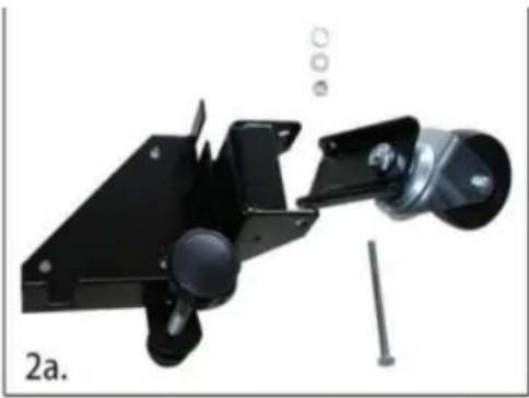
c. Install the swivel plate using the M8-75 carriage bolt, lock washer, and nut. Tighten.
d. Install the foot lever using the M8-75 carriage bolt, nylon washers, lock washer, and nut.
natural_image
Mechanical assembly with black frame and mechanical component, labeled '2a.' (no text or symbols on the diagram itself)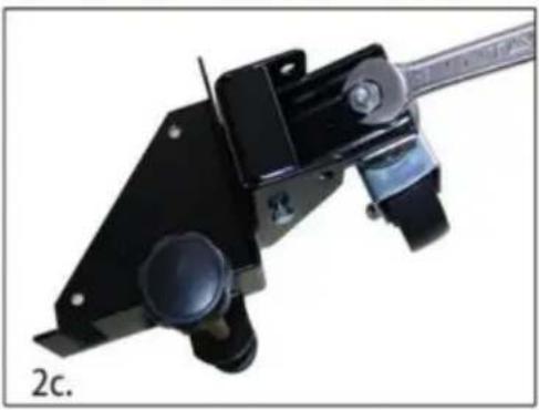
natural_image
Mechanical component with black frame and attached lever, labeled '2c.' (no text or symbols on the object itself)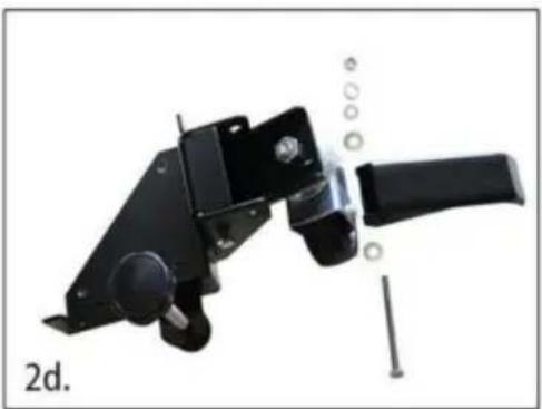
natural_image
Mechanical component with a black handle and bolt, labeled '2d.' (no text or symbols on the object itself)2.
e. Repeat this process for the other swivel bracket
- Assemble the back corners, to the right are the components you will need:
a. Install the back wheel using the M6×47-10 axle bolt, nylon wheel bushing, and M6 lock nut.
-
Carefully measure the footprint of your machine (or whatever you are mobilizing) and add about 1" to the dimension. (1" allows clearance for the fasteners).
-
Review the assembly examples shown below to help you determine the fixed wheel, caster and leveler placement. As these are examples only, you must determine what best suits your particular machine's requirements for stability.
Tighten all hardware securely

natural_image
Mechanical clamp device with black frame and metal handle (no visible text or symbols)
natural_image
Disassembled metal bracket components including a circular component and two separate views (no text or symbols visible)
natural_image
Close-up of a black metal bracket being adjusted with a tool, no visible text or symbolsAssembly Examples
Be sure to follow Safety and Assembly Instructions. Keep in mind the actual operation of your machine and the effect it has on overall stability.

A long, narrow base, such as on a jointer, would benefit from this arrangement. Most machines may be arranged to the convenience of the user.
A short, narrow base, such as found on a drill press or bandsaw, may benefit from this arrangement. Due to swivel rotation, base may sit out of level. Rotate swivel wheel away from base to correct.
- Cut the plywood you are using down to size.

natural_image
Square metal plate with horizontal grooves, labeled '6' at bottom left (no other text or symbols)- You will now need to attach the corners to the plywood, begin by marking the holes using the corner plates as your template.

natural_image
Close-up of hands installing or adjusting a black metal bracket on a wooden surface (no text or symbols visible)- Drill the holes using a 12 " drill bit, it is a good idea to check that the holes are lined up to the plate before drilling each hole.
natural_image
Close-up of a hand using a drill pen to draw a screw on a wooden surface (no text or symbols visible)- Each corner should now look like this.

natural_image
Close-up of a wooden plank with two small holes, labeled '9' in the corner (no other text or symbols)Machine Translated by Google
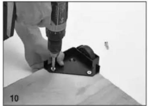
- Attach the corners in the correct positions using the Philips screwdriver, do not tighten the bolts until all three machine screws are partially threaded into the bottom plate.

natural_image
Close-up of a hand using a drill bit to adjust or install a mechanical component (no visible text or symbols)
natural_image
Black metal bracket component mounted on a wooden surface, labeled '10' in corner (no other text or symbols)- Congratulations! You have successfully completed assembly of the GZB88096 mobile base.
MANTENIMIENTO
Importado a AUS: SIHAO PTY LTD, 1 ROKEVA STREETEASTWOOD NSW 2122 Australia
Importado a EE. UU.: Sanven Technology Ltd., Suite 250, 9166 Anaheim Place, Rancho Cucamonga, CA 91730

E-CrossStu GmbH
C/O YH Consulting Limited Oficina 147, Centurion House, London Road, Staines upon Thames, Surrey, TW18 4AX
VEVOR®
TOUGH TOOLS, HALF PRICE
natural_image
Product assembly of black mechanical clamps with metal hardware and bolted components (no text or symbols visible)| Lista części | |||||
| Opis | S/N | Ilość | S/N | Opis | Ilość |
| NAROŻNIK, LEWY Z KÓŁKAMI NAWIAS | 1 | ŚRUBA | MASZYNOWA M8-30 12 | ||
| NAROŻNIK, PRAWY Z KÓŁKAMI NAWIAS | 1 | ŚRUBA | MASZYNOWA M8-40 12 | ||
| NAROŻNIK, LEWY Z KOŁEM MIESZKANIA | 1 | PŁYTA | OBROTOWA | 2 | |
| NAROŻNIK, PRAWY Z KOŁEM MIESZKANIA | Śruba nośna 1 8x75 | 2 | |||
| PŁYTA ŚRUBOWA | 4 | NYLONOWA DŻWIGNIA NOŻNA TULEJA | 4 | ||
| 3-CALOWE KOŁO OBROTOWE | PODKŁADKA BEZPIECZEŃSTWA 2 M8 | 2 | |||
| NAKRĘTKI M10, KOŁNIERZOWE/ZĄBKOWANE | 4 | NAKRĘTKA M-8 SAMOBLOKUJĄCA | 2 | ||
| OKRAGŁE STOPKI | 2 | DŻWIGNIA NOŻNA | 2 |
| NAKRĘTKA ZABEZPIECZAJĄCA M10 | ŚRUBA PODSTAWOWA 2 6 x 75 | 2 | |
| DŁUGI UCHWYT TYPU | 2 | NYLONOWE KOŁO M6TULEJA | |
| 3-calowe KOŁO | 2 | NAKRĘTKA M6, SAMOBLOKUJĄCA | 4 |
| MASZYNA 6x 47-10ŚRUBA, OSI | |||
- Unpack and identify all components and hardware. Make sure there are no missing parts and that there is no shipping damage.
Note: Read instructions thoroughly before proceeding.
- Assemble the front corners:
a. Thread the rubber glide foot into the bracket, then thread the jam nut onto the top
b. Attach the wheel to the swivel plate.
c. Install the swivel plate using the M8-75 carriage bolt, lock washer, and nut. Tighten.
d. Install the foot lever using the M8-75 carriage bolt, nylon washers, lock washer, and nut.

natural_image
Mechanical device with black frame and attached sensor or camera component, labeled '2a.' (no text or symbols on the device itself)
natural_image
Mechanical component with black frame and metallic rod, labeled '2c.' (no text or symbols on the object itself)
natural_image
Mechanical component with attached lever and screw assembly (no visible text or symbols)2.
e. Repeat this process for the other swivel bracket
- Assemble the back corners, to the right are the components you will need:
a. Install the back wheel using the M6×47-10 axle bolt, nylon wheel bushing, and M6 lock nut.
-
Carefully measure the footprint of your machine (or whatever you are mobilizing) and add about 1" to the dimension. (1" allows clearance for the fasteners).
-
Review the assembly examples shown below to help you determine the fixed wheel, caster and leveler placement. As these are examples only, you must determine what best suits your particular machine's requirements for stability.
Tighten all hardware securely

natural_image
Close-up of a black mechanical clamp or lever mechanism with a knob and metal bracket (no visible text or symbols)
natural_image
Disassembled metal bracket components including a circular component and two separate views (no text or symbols visible)
natural_image
Close-up of a black metal bracket being adjusted with a tool, no visible text or symbolsAssembly Examples
Be sure to follow Safety and Assembly Instructions. Keep in mind the actual operation of your machine and the effect it has on overall stability.

A long, narrow base, such as on a jointer, would benefit from this arrangement. Most machines may be arranged to the convenience of the user.

A short, narrow base, such as found on a drill press or bandsaw, may benefit from this arrangement. Due to swivel rotation, base may sit out of level. Rotate swivel wheel away from base to correct.
- Cut the plywood you are using down to size.

natural_image
Square metal plate with horizontal grooves, labeled '6' at bottom left (no other text or symbols)- You will now need to attach the corners to the plywood, begin by marking the holes using the corner plates as your template.

natural_image
Close-up of hands installing or adjusting a black metal bracket on a wooden surface (no text or symbols visible)- Drill the holes using a 12 " drill bit, it is a good idea to check that the holes are lined up to the plate before drilling each hole.

natural_image
Close-up of a hand using a drill pen to draw a screw on a wooden surface (no text or symbols visible)- Each corner should now look like this.

natural_image
Close-up of a wooden plank with two small holes, labeled '9' in the corner (no other text or symbols)Machine Translated by Google
- Attach the corners in the correct positions using the Philips screwdriver, do not tighten the bolts until all three machine screws are partially threaded into the bottom plate.

natural_image
Close-up of a hand using a drill bit to adjust or install a mechanical component (no visible text or symbols)
natural_image
Black metal bracket with mounting holes on a wooden surface (no text or symbols visible)- Congratulations! You have successfully completed assembly of the GZB88096 mobile base.
KONSERWACJA
Import do AUS: SIHAO PTY LTD, 1 ROKEVA STREETEASTWOOD NSW 2122 Australii
Import do USA: Sanven Technology Ltd., Suite 250, 9166 Anaheim Place, Rancho Cucamonga, CA 91730
| REPREZENT KE |
E-CrossStu GmbH
Mainzer Landstr.69, 60329 Frankfurt nad Menem.
C/O YH Consulting Limited Office 147, Centurion House, London Road, Staines-upon-Thames, Surrey, TW18 4AX
VEVOR®
TOUGH TOOLS, HALF PRICE
www.vevor.com/support
VEVOR®
TOUGH TOOLS, HALF PRICE
www.vevor.com/support
MOBIELE BASIS
MODEL: GZB88096
natural_image
Product assembly of black mechanical clamps with metal hardware and bolted components (no text or symbols visible)Foto ter referentie
HULP NODIG? NEEM CONTACT MET ONS OP!
| Onderdelenlijst | |||||
| S/N-beschrijving | Aantal S/N | Beschrijving | Aantal | ||
| ÿ | HOEK, LH MET ZWENKWIEL BEUGEL | 1ÿ | M8-30 | MACHINESCHROEF 12 | |
| ÿ | HOEK, RECHTS MET ZWENKWIEL BEUGEL | 1ÿ | M8-40 | MACHINESCHROEF 12 | |
| ÿ | HOEK, LINKS MET WIEL HUISVESTING | 1ÿ | DRAAIPLAAT | 2 | |
| ÿ | HOEK, RECHTS MET WIEL HUISVESTING | 1ÿ | 8x75 | slotbout | 2 |
| ÿ BOUTPLAAT | 4ÿ | NYLON VoetHENDEL BUS | 4 | ||
| ÿ 3" | ZWENKWIEL | 2ÿ | M8 | BORGRING | 2 |
| ÿ | M10 MOEREN, GEFLENSD/GEKARTELD | 4ÿ | M-8 | MOER ZELFBORGEND | 2 |
| ÿ RONDE VOETEN | 2ÿ | VOETHENDEL | 2 |
| ÿ M10 VASTMOER | 2ÿ | 6 x 75 DRAAGBOUT | 2 |
| ÿ LANGE STEELHENDEL | 2ÿ | M6 NYLON WIELBUS | |
| ÿ 3" WIEL | 2ÿ | M6 MOER, ZELFBORGEND | 4 |
| ÿ | 6x 47-10-MACHINESCHROEF, AS |
- Unpack and identify all components and hardware. Make sure there are no missing parts and that there is no shipping damage.
Note: Read instructions thoroughly before proceeding.
- Assemble the front corners:
a. Thread the rubber glide foot into the bracket, then thread the jam nut onto the top
b. Attach the wheel to the swivel plate.
c. Install the swivel plate using the M8-75 carriage bolt, lock washer, and nut. Tighten.
d. Install the foot lever using the M8-75 carriage bolt, nylon washers, lock washer, and nut.

natural_image
Mechanical assembly with black frame and mechanical component, labeled '2a.' (no text or symbols on the main diagram)
natural_image
Mechanical component with black frame and attached lever, labeled '2c.' (no text or symbols on the object itself)
natural_image
Mechanical component with a black handle and bolt, labeled '2d.' (no text or symbols on the object itself)2.
e. Repeat this process for the other swivel bracket
- Assemble the back corners, to the right are the components you will need:
a. Install the back wheel using the M6×47-10 axle bolt, nylon wheel bushing, and M6 lock nut.
-
Carefully measure the footprint of your machine (or whatever you are mobilizing) and add about 1" to the dimension. (1" allows clearance for the fasteners).
-
Review the assembly examples shown below to help you determine the fixed wheel, caster and leveler placement. As these are examples only, you must determine what best suits your particular machine's requirements for stability.
Tighten all hardware securely
natural_image
Close-up of a black mechanical clamp or lever mechanism with a knob and metal bracket (no visible text or symbols)
natural_image
Disassembled metal bracket components including a circular component and two separate views (no text or symbols visible)
natural_image
Close-up of a black metal bracket being adjusted with a tool, no visible text or symbolsAssembly Examples
Be sure to follow Safety and Assembly Instructions. Keep in mind the actual operation of your machine and the effect it has on overall stability.
A long, narrow base, such as on a jointer, would benefit from this arrangement. Most machines may be arranged to the convenience of the user.

A short, narrow base, such as found on a drill press or bandsaw, may benefit from this arrangement. Due to swivel rotation, base may sit out of level. Rotate swivel wheel away from base to correct.
- Cut the plywood you are using down to size.

natural_image
Square metal plate with horizontal grooves, labeled '6' at bottom left (no other text or symbols)- You will now need to attach the corners to the plywood, begin by marking the holes using the corner plates as your template.

natural_image
Close-up of hands installing a black metal bracket with a tool, placed on a wooden surface (no text or symbols visible)- Drill the holes using a 12 " drill bit, it is a good idea to check that the holes are lined up to the plate before drilling each hole.

natural_image
Close-up of a hand using a drill pen to draw a screw on a wooden surface (no text or symbols visible)- Each corner should now look like this.

natural_image
Close-up of a wooden plank with two small holes, labeled '9' in the corner (no other text or symbols)Machine Translated by Google
- Attach the corners in the correct positions using the Philips screwdriver, do not tighten the bolts until all three machine screws are partially threaded into the bottom plate.

natural_image
Close-up of a hand using a drill bit to adjust or install a mechanical component (no visible text or symbols)
natural_image
Black metal bracket with mounting holes on a wooden surface (no text or symbols visible)- Congratulations! You have successfully completed assembly of the GZB88096 mobile base.
ONDERHOUD
C/O YH Consulting Limited Kantoor 147, Centurion House, London Road, Staines-upon-Thames, Surrey, TW18 4AX
VEVOR®
TOUGH TOOLS, HALF PRICE
Technische ondersteuning en e- garantiecertificaat www.vevor.com/support
VEVOR®
TOUGH TOOLS, HALF PRICE
www.vevor.com/support
MOBIL BAS
MODELL: GZB88096
natural_image
Product assembly of black mechanical clamps with metal hardware and bolted components (no text or symbols visible)Foto för referens
BEHÖVER HJÄLP? KONTAKTA OSS!
| Delarlista | |||||
| S/N | Beskrivning | Antal | S/N | Beskrivning | Antal |
| ÿ | HÖRN, VÄNSTER M/HJUL KONSOL | 1ÿ | M8-30 | MASKINSKRUV 12 | |
| ÿ | HÖRN, RH M/HJUL KONSOL | 1ÿ | M8-40 | MASKINSKRUV 12 | |
| ÿ | HÖRN, LH M/HJUL HUS | 1ÿ | SLUTPLATTA | 2 | |
| ÿ | HÖRN, HÖGER M/HJUL HUS | 1ÿ | 8x75 vagnsbult | 2 | |
| ÿ BULTPLATA | 4ÿ | NYLON FotspakBUSHING | 4 | ||
| ÿ 3" VÄNGLIGT HJUL | 2ÿ | M8 LÅBRICKA | 2 | ||
| ÿ | M10 NÖTTER, FLÄNSAD/TANDIG | 4ÿ | M-8 MUTTER SJÄLVLÅSANDE | 2 | |
| ÿ RUNDA FÖTTER | 2ÿ | FOTSPAK | 2 | ||
| ÿ M10 SLUTMUTTER | 2ÿ | 6 x 75 | BOLTEN | 2 | |
| ÿ LÅNGT STÅP HANDTAG | 2ÿ | M6 NYLON HJUL BUSHING | 4 | ||
| ÿ 3" HJUL | 2ÿ | M6 MUTTER, SJÄLVLÅSANDE | 4 | ||
| ÿ | 6x 47-10 MASKIN SKRUV, AXEL | 2 | |||
- Unpack and identify all components and hardware. Make sure there are no missing parts and that there is no shipping damage.
Note: Read instructions thoroughly before proceeding.
- Assemble the front corners:
a. Thread the rubber glide foot into the bracket, then thread the jam nut onto the top
b. Attach the wheel to the swivel plate.
c. Install the swivel plate using the M8-75 carriage bolt, lock washer, and nut. Tighten.
d. Install the foot lever using the M8-75 carriage bolt, nylon washers, lock washer, and nut.

natural_image
Mechanical assembly with black frame and cylindrical component, labeled '2a.' (no text or symbols on main subject)
natural_image
Mechanical component with black frame and metallic rod, labeled '2c.' (no text or symbols on the object itself)
natural_image
Mechanical component with attached lever and screw assembly (no visible text or symbols)2.
e. Repeat this process for the other swivel bracket
- Assemble the back corners, to the right are the components you will need:
a. Install the back wheel using the M6×47-10 axle bolt, nylon wheel bushing, and M6 lock nut.
-
Carefully measure the footprint of your machine (or whatever you are mobilizing) and add about 1" to the dimension. (1" allows clearance for the fasteners).
-
Review the assembly examples shown below to help you determine the fixed wheel, caster and leveler placement. As these are examples only, you must determine what best suits your particular machine's requirements for stability.
Tighten all hardware securely

natural_image
Close-up of a black mechanical clamp or lever mechanism with a knob and metal bracket (no visible text or symbols)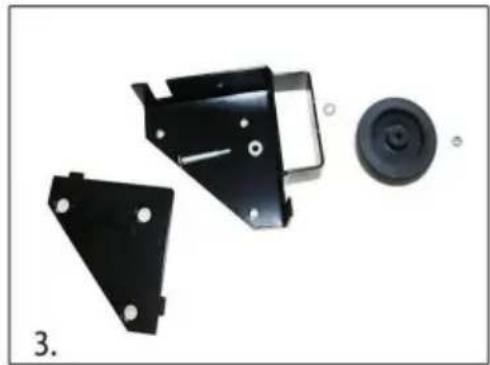
natural_image
Disassembled metal bracket components including a circular component and two separate views (no text or symbols visible)
natural_image
Close-up of a black metal bracket being adjusted with a tool, no visible text or symbolsAssembly Examples
Be sure to follow Safety and Assembly Instructions. Keep in mind the actual operation of your machine and the effect it has on overall stability.

A long, narrow base, such as on a jointer, would benefit from this arrangement. Most machines may be arranged to the convenience of the user.

A short, narrow base, such as found on a drill press or bandsaw, may benefit from this arrangement. Due to swivel rotation, base may sit out of level. Rotate swivel wheel away from base to correct.
- Cut the plywood you are using down to size.

natural_image
Square metal plate with horizontal grooves, labeled '6' at bottom left (no other text or symbols)- You will now need to attach the corners to the plywood, begin by marking the holes using the corner plates as your template.

natural_image
Close-up of hands installing or adjusting a black metal bracket on a wooden surface (no text or symbols visible)- Drill the holes using a 12 " drill bit, it is a good idea to check that the holes are lined up to the plate before drilling each hole.

natural_image
Close-up of a hand using a drill pen to draw a screw on a wooden surface (no text or symbols visible)- Each corner should now look like this.
natural_image
Close-up of a wooden plank with two small holes, labeled '9' in the corner (no other text or symbols)Machine Translated by Google
- Attach the corners in the correct positions using the Philips screwdriver, do not tighten the bolts until all three machine screws are partially threaded into the bottom plate.
natural_image
Close-up of a hand using a drill bit to adjust or install a mechanical component (no visible text or symbols)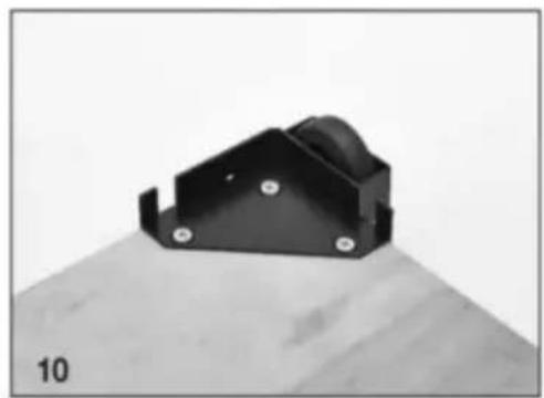
natural_image
Black metal bracket with mounting holes on a wooden surface (no text or symbols visible)- Congratulations! You have successfully completed assembly of the GZB88096 mobile base.
UNDERHÅLL
C/O YH Consulting Limited Office 147, Centurion House, London Road, Staines-upon-Thames, Surrey, TW18 4AX
VEVOR®
TOUGH TOOLS, HALF PRICE