
BCH5300BP - String Trimmer SCHEPPACH - Free user manual and instructions
Find the device manual for free BCH5300BP SCHEPPACH in PDF.

| Product type | Gasoline grass trimmer / brushcutter |
| Brand | Scheppach |
| Model | BCH5300BP |
| Engine | 2-stroke, air-cooled, 51.7 cm³, 2.3 kW |
| Displacement | 51.7 cm³ |
| Fuel tank | 1000 cm³ |
| Fuel mixture | Unleaded gasoline + 2-stroke oil, ratio 40:1 |
| Cutting diameter (trimmer) | 450 mm |
| Cutting diameter (brushcutter) | 255 mm |
| Maximum speed (trimmer) | 7500 min⁻¹ |
| Maximum speed (brushcutter) | 7800 min⁻¹ |
| Blade thickness | 1.4 mm |
| Weight | 11.47 kg |
| Sound pressure level | 100.4 dB(A) |
| Sound power level | 115.71 dB(A) |
| Vibration (trimmer) | Front 6.66 m/s², rear 7.68 m/s² |
| Vibration (brushcutter) | Front 5.26 m/s², rear 5.08 m/s² |
| Line type | Nylon, diameter 2 x 2.8 mm, length 4 m |
| Included accessories | Backpack, mixing bottle, keys, collars |
| Usage | Cutting grass, weeds, brush, small wood |
| Safety | Harness with emergency release, protections |
Frequently Asked Questions - BCH5300BP SCHEPPACH
User questions about BCH5300BP SCHEPPACH
0 question about this device. Answer the ones you know or ask your own.
Ask a new question about this device
Download the instructions for your String Trimmer in PDF format for free! Find your manual BCH5300BP - SCHEPPACH and take your electronic device back in hand. On this page are published all the documents necessary for the use of your device. BCH5300BP by SCHEPPACH.
USER MANUAL BCH5300BP SCHEPPACH
natural_image
Scheppch precision tool with metal angle and power supply (no visible text or symbols)| DE | Benzin Freischneider / GrastrimmerOriginalbetriebsanleitung | 10 - 21 |
| GB | Brush Cutter / Grass trimmerTranslation from the original instruction manual | 22 - 32 |
| FR | Débroussailleuse / coupe-herbe à essenceTraduction des instructions d'origine | 33 - 44 |


ACHTUNG!:
CAUTION!
ATTENTION!:
Read the manual carefully before operating this machine!

natural_image
Black plastic swimmer device with attached grip and screw base (no text or symbols visible)
natural_image
Close-up of a hand using a tool to adjust a black cable or cable with a rotating knob (no text or symbols visible)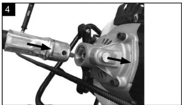
natural_image
Close-up of a mechanical assembly with a tool and connector (no visible text or symbols)
natural_image
Close-up of a hand adjusting a mechanical component with wires and connectors (no visible text or symbols)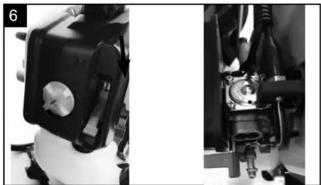
natural_image
Close-up of mechanical components with no visible text or symbols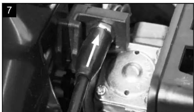
natural_image
Close-up of a mechanical component with a white arrow pointing to a cylindrical component (no visible text or symbols)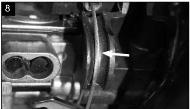
natural_image
Close-up mechanical component with a white arrow pointing to a specific part (no visible text or symbols)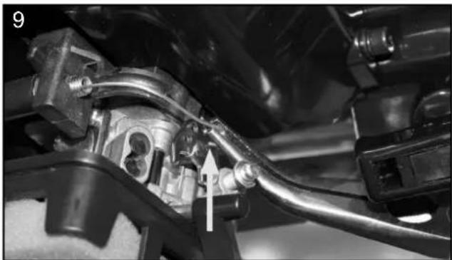
natural_image
Close-up of a mechanical assembly with a curved pipe and valve, no visible text or symbols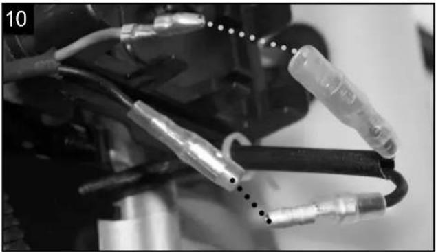
natural_image
Close-up of mechanical components with wires and connectors (no visible text or symbols)
natural_image
Close-up of a mechanical component with multiple metallic clamps and wires, no visible text or symbols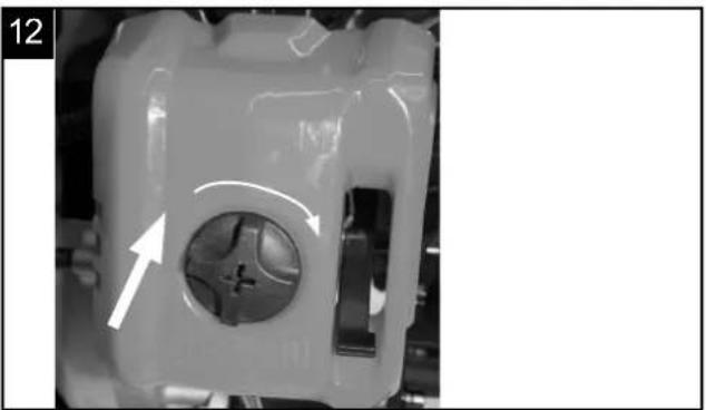
natural_image
Close-up of a mechanical component with a circular hole and directional arrows indicating motion (no text or symbols)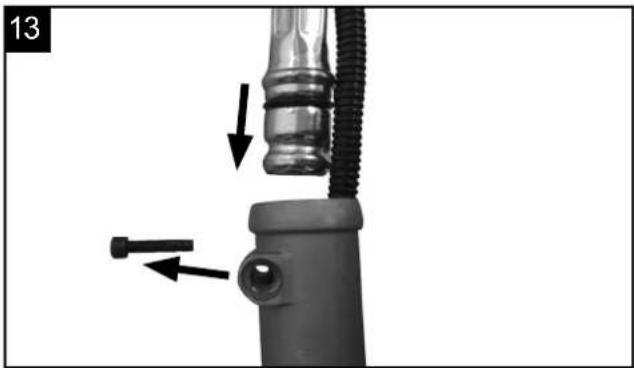
natural_image
Close-up of a mechanical component with arrows indicating movement or assembly (no text or symbols visible)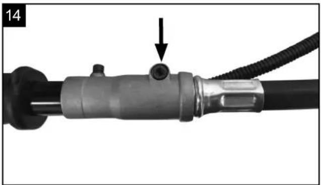
natural_image
Close-up of a mechanical component with a black cylindrical body and coiled cable, showing a small circular feature and an arrow pointing to it (no text or symbols present)
natural_image
Two black-and-white diagrams showing a cable or connector with arrows indicating direction, no text or symbols present.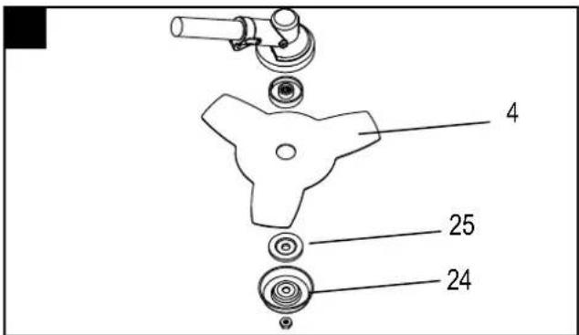
natural_image
Close-up of hands operating a propeller with a rotating knob (no text or symbols visible)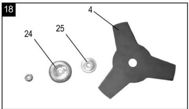

natural_image
Close-up of hands performing a mechanical assembly with a tool, no visible text or symbols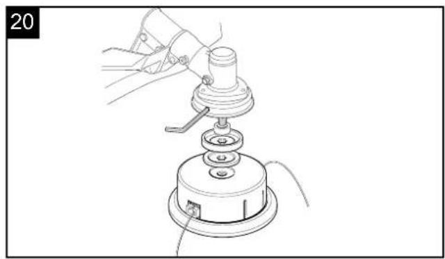
natural_image
Line drawing of a mechanical assembly with a hand operating a tool on a base (no text or symbols)
natural_image
Close-up of a metallic pipe fitting with bolts and clamps (no visible text or symbols)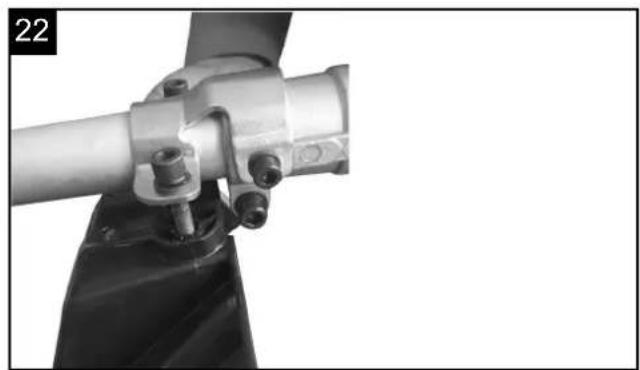
natural_image
Close-up of a mechanical assembly with a metallic pipe and black fabric (no visible text or symbols)
natural_image
Close-up of hands using a screwdriver to adjust a mechanical component (no visible text or symbols)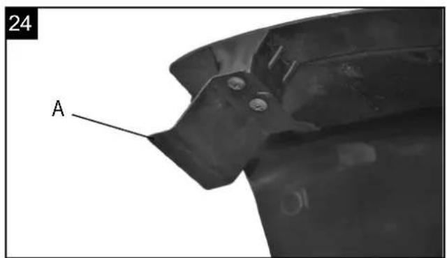

natural_image
Person wearing a black athletic harness with a circular button, shown in side profile (no text or symbols visible)
natural_image
Person wearing a black athletic vest with straps, standing in a relaxed pose (no text or symbols visible)
natural_image
Close-up of a person's backrest with black straps and a white arrow indicating a specific location (no text or symbols)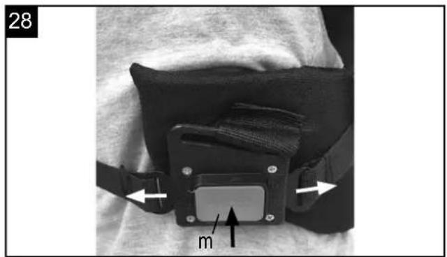

natural_image
Black tactical vest with attached straps and straps, no visible text or symbols
natural_image
Close-up of a mechanical component with a tool and part number 10, no visible text or symbols
natural_image
Close-up of hands using a sewing machine to adjust or install a component, no visible text or symbols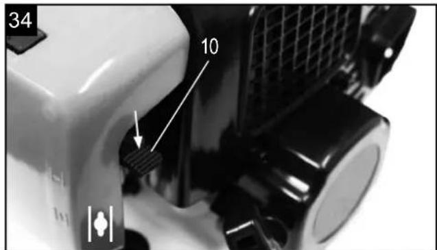

natural_image
Two black-and-white photos showing a hand holding a bag and a close-up of the device with arrows indicating motion (no text or symbols)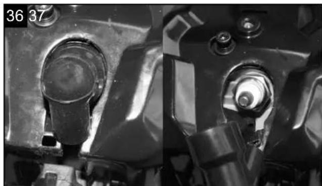
natural_image
Close-up of mechanical components with no visible text or symbols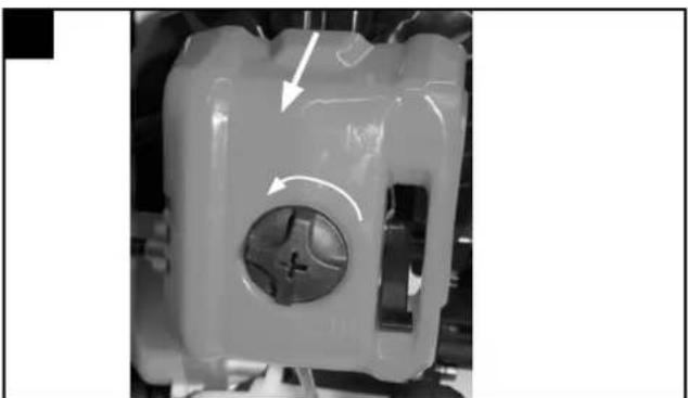
natural_image
Close-up of a mechanical component with a central hole and directional arrows indicating motion (no text or symbols)38
natural_image
Close-up of a mechanical component with a black circular feature and an arrow pointing to it (no visible text or symbols)39

natural_image
Close-up of a mechanical component with bolts and mounting holes (no visible text or symbols)40
natural_image
Close-up of hands adjusting a mechanical component with hoses and a small component (no visible text or symbols)41

natural_image
Close-up of a hand holding a circular mechanical component with concentric rings and a central hole (no text or symbols visible)
natural_image
Two hands holding a mechanical component, showing internal components and a close-up of the interior (no text or symbols visible)
natural_image
Two hands holding a mechanical component with internal springs, showing a close-up of the interior (no text or symbols visible)44
natural_image
Technical line drawing of a mechanical component with gears and a central hub (no text or symbols)45

46

natural_image
Line drawing of a simple chair with a circular top and four legs (no text or symbols)m = 311

natural_image
Close-up of a hand inserting a plastic component into a cylindrical tube (no text or symbols visible)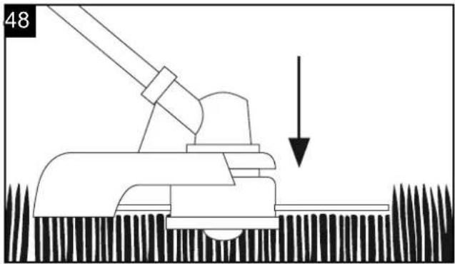
natural_image
Diagram of a mechanical device with a downward arrow indicating motion or force (no text or symbols present)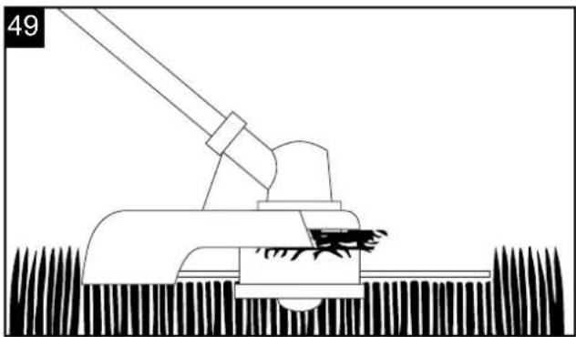
natural_image
Line drawing of a mechanical tool interacting with a textured surface (no text or symbols)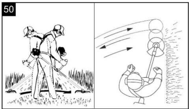
natural_image
Close-up mechanical assembly showing a gear and shaft assembly (no visible text or symbols)Inhaltsverzeichnis:
Seite:
Günzburger Straße 69
D-89335 Ichenhausen
VEREHRTER KUNDE,
- Introduction 24
- Device description 24
- Scope of delivery 24
- Intended use 25
- Important information 25
- Technical data 26
- Before starting the equipment 27
-
Attachment and operation 27
-
Working instructions 29
-
Maintenance 30
-
Storage 31
-
Disposal and recycling 32
-
Troubleshooting 32
Explanation of the symbols on the equipment
 | Read the instruction manual. |
 | Warning! Gasoline is very flammable. Avoid smoking or bringing any flame or sparks near fuel. |
 | Warning! Denotes risk of personal injury, loss of life, or damage to the tool in case of non-observance. |
 | Warning! Risk of injury! Do not let your hands or feet come in contact with the blades when the motor is running.. |
 | Warning! Keep all children, bystanders and helpers 15 meters away from the brush cutter! |
 | Wear robust footwear when using the device! |
 | Wear protective helmet, ear and eye protection. |
 | Wear protective gloves when using the device! |
 | Warning! The exhaust and other parts of the engine will get very hot during use, do not touch! |
 | Symbol for refuelling the "MIX GASOLINE" on fuel tank cap. |
 | Warning! Beware of thrown objects hit by cutting attachments. Never use without properly mounted blade guard. |
 | The product complies with the applicable European directives and an evaluation method of conformity for this directives was done. |
 | Caution kickback! |
 | Caution,use no saw blades or multipart metal cutting tools! |
 | Brush cutter |
 | Grass trimmer |
 | Guaranteed sound power |
 | Fuel tank capacity |
 | Petrol pump, Primer |
| Start lever (choke) "cold start"Start lever (choke) "warm start and work" | |
1. Introduction
MANUFACTURER:
scheppach
Günzburger Straße 69
D-89335 Ichenhausen
DEAR CUSTOMER,
We hope your new tool brings you much enjoyment and success.
NOTE:
According to the applicable product liability laws, the manufacturer of the device does not assume liability for damages to the product or damages caused by the product that occurs due to:
- Improper handling,
- Non-compliance of the operating instructions,
- Repairs by third parties, not by authorized service technicians,
• Installation and replacement of non-original spare parts,
• Application other than specified, - A breakdown of the electrical system that occurs due to the non-compliance of the electric regulations and VDE regulations 0100, DIN 57113 / VDE0113.
WE RECOMMEND:
Read through the complete text in the operating instructions before installing and commissioning the device. The operating instructions are intended to help the user to become familiar with the machine and take advantage of its application possibilities in accordance with the recommendations. The operating instructions contain important information on how to operate the machine safely, professionally and economically, how to avoid danger, costly repairs, reduce downtimes and how to increase reliability and service life of the machine.
In addition to the safety regulations in the operating instructions, you have to meet the applicable regulations that apply for the operation of the machine in your country. Keep the operating instructions package with the machine at all times and store it in a plastic cover to protect it from dirt and moisture. Read the instruction manual each time before operating the machine and carefully follow its information. The machine can only be operated by persons who were instructed concerning the operation of the machine and who are informed about the associated dangers. The minimum age requirement must be complied with.
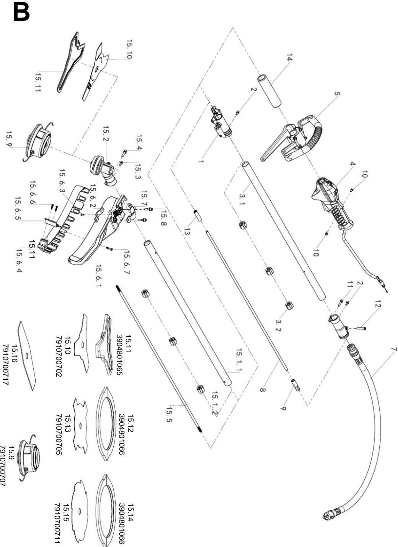
2. Layout (Fig. 1)
Scope of delivery
- Line spool with cutting line
- Safe guard
- Long handle with drive shaft
- Cutting blade (2-/3-/4- and 8-teeth)
- Steady grip
- Switch On/Off
- Throttle lock
- Throttle lever
- Flexible shaft
- Choke lever
- Starter cable
- Spark plug boot
- Air filter housing cover
- Petrol tank
- Housing for engine cooler
- Fuel pump
- Backpack
- Combined oil/petrol cylinder
- Spark plug wrench
- Allen key (size 4)
- Allen key (size 5)
- 5 x cable ties
3. Scope of delivery
- Open the packaging and take out the equipment with care.
- Remove the packaging material and any packaging and/or transportation braces (if available).
- Check to see if all items are present.
- Inspect the equipment and accessories for transport damage. In case of complaints the supplier is to be informed immediately. Complaints received at a later date will not be acknowledged.
- If possible, keep the packaging until the end of the guarantee period.
- Read the operating instructions to make yourself familiar with the device prior to using it.
• After that, please dispose of it in an environmentally friendly way. - Only use original parts for accessories as well as for wearing and spare parts. Spare parts are available from your specialized dealer.
- Specify our part numbers as well as the type and year of construction of the device in your orders.
⚠️ Important!
The equipment and packaging material are not toys. Do not let children play with plastic bags, foils or small parts. There is a danger of swallowing or suffocating!
• Motor drive unit with backpack
- Power scythe
- Grasstrimmer
- Flexible shaft (9)
- Spark plug wrench (19)
- Open-ended spanner (8 mm / 10 mm) (20)
- Allen key (size 4) (21)
- Allen key (size 5) (22)
- 5 x cable ties (23)
• Combined oil/petrol cylinder (18) - Front handle (Fig. 2)
• 4 screws M5 x 35 (Fig. 2) - Cover (Fig. 2)
• 4 nuts M5 (Fig. 2)
4. Intended use
The power scythe (using the cutting blade) is designed for cutting young trees, strong weeds and undergrowth.
The power trimmer (using the line spool with cutting line) is designed for cutting lawns, grassed areas and small weeds. The operating instructions as supplied by the manufacturer must be obeyed to ensure that the equipment is used properly. Any use which is not expressly permitted in the manual may result in damage to the equipment and place the user in serious danger. Be sure to observe the restrictions in the safety instructions.
Please note that our equipment has not been designed for use in commercial, trade or industrial applications. Our warranty will be voided if the equipment is used in commercial, trade or industrial businesses or for equivalent purposes.
Important. Due to the high risk of bodily injury to the user, the petrol power scythe must not be used to carry out the following work: to clean dirt and debris off walkways, or to chop up tree or hedge clippings. Similarly, the petrol power scythe must not be used to level out high areas such as molehills. For safety reasons, the petrol power scythe must not be used as a drive unit for other work tools or toolkits of any kind.
The equipment is allowed to be used only for its prescribed purpose. Any other use is deemed to be a case of misuse. The user/operator and not the manufacturer will be liable for any damage or injuries of any kind resulting from such misuse.
Non-permitted users:
Persons who are not familiar with the operating manual, children, young people under the age of 16 as well as persons under the influence of alcohol, drugs or medication must not operate the unit.
Working hours for gasoline brush cutter
While it is permitted to use a brush cutter at any time, operators should always show due consideration to others living nearby.
5. Important information
Safety instructions
This appliance is not intended for use by persons (including children) with reduced physical, sensory or mental capabilities, or lack of experience and knowledge, unless they have been given supervision or instruction concerning use of the appliance by a person responsible for their safety.
Children should be supervised to ensure that they do not play with the appliance.
1. Training
- Read the instructions carefully. Be familiar with the controls and the proper use of the appliance.
- Never allow children or people unfamiliar with these instructions to use the appliance. Local regulations may restrict the age of the operator.
- Never mow while people, especially children, or pets are nearby.
- The operator or user is responsible for accidents of hazards occurring to other people or their property.
- Avoid running the engine indoors. The exhaust gases contain harmful carbon monoxide.
2. Preparation
- While cutting, always wear substantial footwear and long trousers.
- Do not operate the appliance when barefoot or wearing open sandals.
- Thoroughly inspect the area where the appliance is to be used and remove all stones, sticks, wires, bones, and other foreign objects.
- Before using, always visually inspect to see that the blades, blade bolts and cutter assembly are not worn or damaged. Replace worn or damaged blades and bolts in sets to preserve balance.
- On multi-bladed appliances, take care as rotating one blade can cause other blades to rotate.
3. Operation
- Operate only in daylight or in good artificial light.
- Avoid operating the appliance in wet grass, where feasible.
• Always be sure of your footing on slopes. - Walk, never run.
- Exercise extreme caution when changing direction on slopes.
- Do not cutting excessively steep slopes.
- Use extreme caution when reversing or pulling the appliance towards you.
- Never operate the appliance with defective guards or shields, or without safety devices.
- Switch on the motor according to instructions and with feet well away from the blade(s).
-
In this case, do not tilt it more than absolutely necessary and lift only the part which is away from the operator. Always ensure that both hands are in the operating position before returning the appliance to the ground.
-
Do not put hands or feet near or under rotating parts.
- Never pick up or carry an appliance while the motor is running.
- Pull the spark from the socket:
– whenever you leave the machine;
– before clearing a blockage;
– before checking, cleaning or working on the appliance;
– after striking a foreign object. Inspect the appliance for damage and make repairs as necessary; -
if the appliance starts to vibrate abnormally (check immediately).
-
Maintenance and storage
-
Keep all nuts, bolts, and screws tight to be sure the appliance is in safe working condition.
- Check the grass catcher frequently for wear or deterioration.
- Replace worn or damaged parts for safety.
- For rotary mowers, ensure that only replacement cutting means of the right type are used.
– Never store the equipment with petrol in the tank inside a building where fumes can reach an open flame or spark; - Allow the engine to cool before storing in any enclosure;
- To reduce the fire hazard, keep the engine, silencer, battery compartment and petrol storage area free of grass, leaves, or excessive grease;
- If the fuel tank has to be drained, this should be done outdoors.
Special safety warning
- Grip the handles of the brush cutter firmly with both hands. If you suspend the work, place the throttle into the idling position.
- Always be sure to maintain a steady, even posture while working
- Maintain the speed of the engine at the level required to perform cutting work and never raise the speed of the engine above the necessary level.
- If the grass gets caught in the blade during operation, or if you need to check the unit or refuel the tank always be sure to turn off the engine.
- If the blade touches a hard object like a stone immediately stop the engine and check if something is wrong with the blade. If so, replace the blade with a new one.
- If someone calls out while working, always be sure to turn off the engine before turning around.
- Never touch the spark plug or plug cord while the engine is in operation. Doing so may result in being subjected to an electrical shock.
-
Never touch the muffler, spark plug or other metallic parts of the engine while the engine is in operation or immediately after shutting down the engine. Doing so may result in serious burns.
-
When you finish cutting in one location and wish to continue working in another spot, turn off the engine and turn the machine to have the blade facing away from your body.
-
Check that the cutting attachment stopped turning under the engine idle before starting to use the machine.
Residual risks
- There will always be residual risks, even if you use this equipment according to instructions. The following hazards can occur in connection with the construction and design of this tool.
- Health hazards resulting from swinging of hand and arm if the equipment is used for an extended period and if it is not operated or maintained properly.
- Injuries and material damage caused by ejection of tool attachments which are unexpectedly thrown from the equipment because of sudden damage, wear and tear or improper attachment.
- Warning! This tool generates an electromagnetic field during operation. Under certain circumstances, this field can affect active or passive medical implants. In order to reduce the risk of severe or fatal injuries, we recommend that people with medical implants consult their doctor and the manufacturer of the medical implant before operating the machine.
Before working on the tool itself (e.g. transport, set-up, retooling, cleaning and maintenance), disconnect the spark plug cap!
6. Technical data
| BCH5300BP | |
| Technical data | |
| Cutting data grass trimmer | |
| Cutting circle diameter of line mm | 450 |
| Cutting line diameter mm | 2 x 2.8 |
| Cutting line length m | 4 |
| Max. cutting speed max. min ^-1 | 7500 |
| Cutting data brush cutter | |
| Cutting circle diameter of blade mm | 255 |
| Cutter balde thickness mm | 1.4 |
| Teeth quantity | 3 |
| Max. cutting speed max. min ^-1 | 7800 |
| Power unit | |
| Displacement cm ^3 | 51.7 |
| Max. engine output kW | 1.3 |
| Fuel tank capacity cm ^3 | 1000 |
| Engine type | 2-stroke engine, air-cooled |
| Weight kg | 11,47 |
Subject to technical changes!
Information concerning noise emission measured according to relevant standards:
Sound pressure L_pA = 100,4dB(A)
Sound power L_WA = 115,71 dB(A)
Uncertainty K_PA = 3 dB(A)
Wear ear-muffs.
The impact of noise can cause damage to hearing.
Vibration:
Grass trimmer: A_hv = Front 6,66 m/s ^2 Rear 7,68 m/s ^2
Brush cutter: A_hw = Front 5,26 m/s ^2 Rear 5,08 m/s ^2
Uncertainty K_PA = 1.5 m/s^2
Reduce noise generation and vibration to a minimum!
- Use only equipment that is in perfect condition.
- Maintain and clean the equipment regularly.
- Adopt your way of working to the equipment.
- Do not overload the equipment.
- Have the equipment checked if necessary.
- Switch off the equipment when not in use.
- Wear gloves.
In these operating instructions we have marked the places that have to do with your safety with this sign: △
7. Before starting the equipment
Each time before use, check the following:
- That there are no leaks in the fuel system.
- That the equipment is in perfect condition and that the safety devices and cutting devices are complete.
- That all screws are securely fastened.
- That all moving parts move smoothly.
1 Fuel and oil
Recommended fuels
Use only a mixture of unleaded petrol and special 2-stroke engine oil. Mix the fuel mixture as indicated in the fuel mixing table.
Important: Do not use a fuel mixture which has been stored for longer than 90 days.
Important: Never use 2-stroke oil with a recommended mixing ratio of 100:1. The manufacturer's warranty will be voided in case of engine damage due to inadequate lubrication.
Important: Only use containers designed and approved for the purpose to transport and store fuel.
Pour the correct quantities of petrol and 2-stroke oil into the mixing bottle (see scale printed on the bottle). Then shake the bottle well.
Never use oil for 4-cycle engine or use water cooled 2-cycle engine. It can cause spark plug fouling exhaust part blocking or piston ring sticking.
Mixed fuels, which have been left unused for a period of one month or more, may clog the carburetor or result in the engine foiling to operate property. Put remained fuel into an airtight container and keep it in the dark and cool room.
Fuel mixing table
Mixing procedure: 40 parts petrol to 1 part oil
Example:
1 | Petrol : 0,025 | 2-stroke oil
5 | Petrol : 0,125 | 2-stroke oil
Warning!
Take care of the emission of exhaust gases.
Always shut off engine before fueling. Never add fuel to a machine with a running or hot engine. Take care of fire!
8. Attachment and operation
ASSEMBLY
When assembling this machine, please follow the instructions for assembly printed.
1 Assemble the handle on the machine. Fig. 2-3
• Install the front handle as shown on the image 2.
- Make sure that you align the pin with the hole. Tighten the screws only loosely before you have the most comfortable working position set to the risers. The front handle should be aligned as in pictures 2+3 shown, then tighten the screws.
2 Mounting the flexible shaft Fig. 4-15
- Pull the locking bolt out and affix the flexible shaft to the motor until the locking bolt locks in. Fig. 4, 5
- Open the air filter cover, screw the accelerator cable in as shown and attach to the throttle valve. Fig. 6 - 9
- Secure with a counter nut. The accelerator cable must be able to move from idle to full acceleration freely.
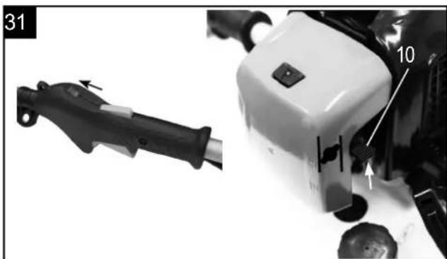
- Connect the ignition interruption cables as shown in figure 10 + 11.
- Secure the air filter cover with a screw again. Fig. 12
- Remove the screw from the handle, insert the other side of the flexible shaft into the handle and use the screw to affix it to the handle. Fig. 13 + 14
- Use cable ties to affix the accelerator cable to the flexible shaft. Fig. 15
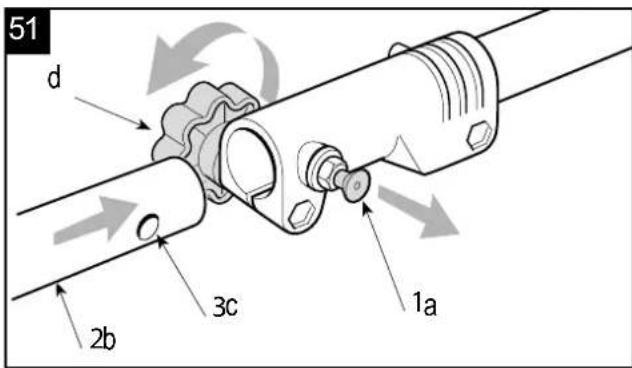
3. Mounting the shaft Fig. 51
- Pull out the locking pin (a) and press the lower part of the shaft (b) downward until the locking pin engages. The bolt (a) is in the right position when it is fully seated in the bore.
- Lastly, tighten the knob (d) securely.
4. Assemble and disassemble the cutting head grass trimmer / nylon cutting head. Fig. 19 - 20
- Release the nut.
Line up the two holes of flange and shield, use one screw driver to hold the flange as below and turn the socket wrench clockwise, the nut will be released.
• Fit the Nylon cutting head.
Remove another shield after release the nut. Still hold the flange, take the Nylon cutting head on the shaft and rotate counter-clockwise, the Nylon cutting head is fitted. Fig. 20 - Release the Nylon cutting head.
Use screw driver to hold flange and then rotate the Nylon cutting head clockwise, it will be replaced.
Brush cutter / Cutter blade
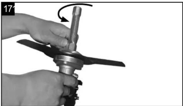
• Fit the blade. Fig. 16 - 18
Take the outer flange off after release the nut, then put the blade (4), outer flange (25), shield (24) and nut according to priority as below picture. Note the blade rotation direction needs be same as below picture. Use screw driver to hold flange and tighten nut counter-clockwise, ensure the nut is tightened enough.
- Release blade. Use screw driver to hold flange and release nut, the blade can be took off.
5. Assemble the safe guard. Fig. 21 23
- Fix the safe guard with hex key and wrench enclosed as standard accessories for tightening the nuts enough. Please see the below pictures showing.
⚠ Warning! Use only original manufacturer's replacement parts, accessories and attachments. Failure to do so can cause poor performance, possible injury and may void your warranty. Never use the machine without the guard assembled!
⚠ Warning!
Please make sure the cutting head has been assembled correctly before use!
Note: The packaging material is made of recycle materials. Dispose of packaging materials in accordance with regulations.
6. Fit the belt. Fig. 25 - 29
- Wear the shoulder strap. Fig. 25 - 27
• Balance the machine when the tool is switched off. - When standing in a normal working posture, the blade should touch the ground during normal working position.
- To fit the backpacks to your body size adjust the straps at the carrying strap. Fig. 29
- Safety button at the carrying strap Fig. 28 ATTENTION! In an emergency, the safety button (m) can be pressed from the harness. The machine then detaches immediately from the carrying strap and falls to the ground.
OPERATION
When working with the equipment, the appropriate plastic guard hood for cutting blade mode or cutting line mode must be fitted to prevent objects being thrown out by the equipment.
The integrated blade in the cutting line guard hood automatically cuts the line to the optimum length.
Fig. 24
Filling with fuel
△ Danger of injury! Fuel is explosive! Turn off and cool the motor down before filling the tank with fuel. You must observe all safety instructions relating to handing fuel.
⚠️ Risk of device damage!
The device is supplied without motor or gearbox oil.
ATTENTION! Before operating, you must fill it with fuel.
- Unscrew the tank cap (B) and remove it. Fig. 32
- Pour in the fuel carefully. Avoid spilling!
- Screw the tank cap on firmly by hand.
Draining fuel. Fig. 47
- Hold a collection container beneath the fuel drain bolt.
- Unscrew the tank cap (B) and remove it.
- Allow the fuel to run out completely.
- Screw the tank cap on firmly by hand.
Start on the unit
Do not start the unit until it has been completely assembled.
⚠ Danger of injury!
Do not operate the device unless you did not find any faults. If a part has become defective, make sure to replace it before you use the device again.
Check before use!
- Check the safe condition of the device:
- Check the device for leaks.
- Check the device for visual defects.
- Check that all parts of the device have been securely fitted.
- Check that all safety devices are in proper condition.
⚠ Danger of injury!
Before starting work, always check the ground and remove all objects which could be thrown by the device.
Start Fig. 30 - 34 + 48
Once the machine has been set up properly, start the engine as follow:
-
Set the equipment down on a hard, level surface.
-
Turn the engine switch (6) to the ON position. Fig. 30, 31
- Put the choke lever on the position. Fig. 31
- Press the fuel pump more than 5 times. Fig. 32
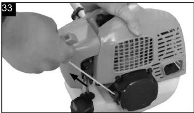
- Pull the recoil starter handle (11) 3-5 times to start the engine. Fig. 33
- Pull the rope until engine starts. Fig. 33
- Press the throttle control lock (7) and the throttle control (8) simultaneously. The choke automatically jumps to the "warm start" operating position.

-
To start the cutting tools, operate the release lever (7) with the palm of your hand, and the throttle lever (8) with your fingers. The further you push the throttle lever, the higher the motor speed. When releasing the throttle lever, the motor becomes idle and the cutting tools stop. Fig. 30. The cutting tools should not continue turning and should not move when the motor is idle. Fig. 30
-
Adjusting line length when working: This machine is fitted with a "Tap & Go" head. To release more line, tap the cutting line head against the round with engine at top speed: the line will be released automatically and the knife cut off the excess length. Fig. 48
-
If meet any problems, press the engine switch to off position, the machine will stop running. If need stop cutting head working, release the throttle lever (8). Fig. 30
-
In an emergency, the safety button (m) can be pressed from the harness. The machine then detaches immediately from the carrying strap and falls to the ground. Fig. 28
-
If the machine is hot, the throttle level can be adjusted to ON position directly when re start the machine.
Note: If the engine does not start up even after several attempts, read the section „Engine troubleshooting“.
Note: Always pull the starter cord out in a straight line. If it is pulled out at an angle, then friction will occur on the eyelet. As a result of this friction, the cable will become frayed and will wear away faster. Always hold the starter handle when the cable retracts.
Never allow the cable to snap back when it has been pulled out.
Note: Do not start the motor in tall grass.
⚠ Attention: When the engine has been switched off, the cutter continues running for several seconds therefore do not close to cutting head of brush cutter until the cutter has come to a standstill!
9. Working instructions
Extending the cutting line
Caution! Do not use any kind of metal wire or metal wire encased in plastic in the line spool. This may cause serious injuries to the user. To extend the cutting line, run the engine at full speed and tap the line spool on the ground. This will automatically extend the line. Fig. 48
The blade (A) on the safety shield will cut the line to the appropriate length. Fig. 24
△ Important: Remove all grass and weed remnants at regular intervals to prevent the shaft tube overheating. Lawn, grass and weed remnants become trapped under the safety shield and prevent the shaft tube from receiving adequate ventilation. Remove the remnants carefully using a screwdriver or the like. Fig. 49
Different cutting methods
When the equipment is correctly assembled it will cut weeds and long grass in places which are difficult to access, e.g. along fences, walls and foundations and also around trees. It can also be used for „mowing“ down vegetation so that a garden can be better prepared or a certain area cleared down to the soil. Fig. 50
⚠ Attention: Even if it is used carefully, cutting around foundations, stone or concrete walls, etc. will result in the line suffering more than normal wear.
Trimming/mowing
Swing the trimmer from side to side in a scything motion. Always keep the line spool parallel to the ground. Check the site and decide which cutting height you require. Guide and hold the line spool at the required height to obtain an even cut. Fig. 50
Low trimming
Hold the trimmer right in front of you at a slight angle so that the underside of the line spool is above the ground and the line strikes the correct target. Always cut away from yourself. Never draw the trimmer towards yourself.
Cutting along fences/foundations
Approach wire mesh fences, lath fences, natural stone walls and foundations slowly so that you can cut close to them without striking the obstacle with the line. If, for example, the line strikes stones, stone walls or foundations, it will wear or fray. If the line strikes wire fencing, it will break.
Trimming around trees
When trimming around tree trunks, approach slowly so that the line does not strike the bark. Walk around the tree, cutting from left to right. Approach grass or weeds with the tip of the line and tilt the line spool forwards slightly.
Warning! Take extreme care during mowing work. When doing such work keep a distance of 30 meters between yourself and other people or animals.
Mowing
When mowing, you want to cut all the vegetation down to the ground. To do this, set the line spool at an angle of 30^ to the right. Place the handle in the required position. Remember the increased risk of injury to the user, watchers and animals, and the danger of damaging property due to objects (for example stones) being thrown.
Warning! Do not use the equipment to remove objects from footpaths, etc. The equipment is a powerful tool and can throw small stones and other objects a distance of 15 meters or more, causing injuries and damage to cars, houses and windows.
Jamming
If the cutting blade jams as a result of attempting to cut vegetation that is too dense, switch off the engine immediately. Remove the grass and scrub from the equipment before you restart it. Fig. 49
Preventing recoil
When you work with the blade, there is a risk of recoil if it strikes solid objects such as tree trunks, branches, tree stumps, stones or the like. This will throw the equipment backwards in the direction opposite to the rotation of the tool. This can cause you to lose control of the equipment. Do not use the blade near fences, metal posts, boundary stones or foundations.
10. Maintenance
Before performing any maintenance or cleaning work, always turn off the engine and pull out the spark boot plug.
-
Do not spray the unit with water. It damages the engine.
-
Clean the unit with a cloth, hand brush, etc.
| Maintenance schedule | |||
| 12 hours of use | 24 hours of use | 36 hours of use | |
| Air filter clean | clean replace | ||
| Spark plug check | clean replace | ||
Expert inspection is required:
- If the brush cutter strikes an object.
• If the motor stops suddenly - If the blade is bent (do not align!)
- If the gears are damaged.
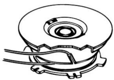
Replacing the line spool/cutting line Fig. 41 - 46
- Dismantle the line spool (1) as described in section 8.3 Assembly. Press the spool together and remove one half of the housing. Fig. 42
-
Take the spool plate out of the line spool housing. Fig. 43
-
Remove any remaining cutting line.
- Place the new cutting line in the center and hang the loop which has formed into the recess in the spool splitter. Fig. 44
- Wind the line onto the spool counter-clockwise and under tension. The spool splitter will separate the two halves of the line. Fig. 45
- Hook the last 15cm of the two ends of the line onto the opposite lying line holders of the spool plate. Fig. 46
- Thread the two ends of the line through the metal eyelets in the line spool housing.
- Press the spool plate into the line spool housing. Fig. 43
- Pull the two line ends sharply to release them from the line holders.
- Join the housing parts together again. Fig. 42
- Cut the excess line to a length of around 13cm. This will reduce the load on the engine when starting and warming up.
- Remount the line spool (see section 8.3). If you are replacing the complete line spool, skip points 3-6.
Grinding the safety hood blade Fig. 24 (A)
The safety hood blade can become blunt over time.
- When you notice this, undo the screw holding the safety hood blade on the safety hood.
- Clamp the blade in a vise.
- Sharpen the blade with a flat file and make sure that the angle of the cutting edge is not altered in the process. File in one direction only.
- Important! Reassemble the cutting knife.
Replacing and resharpening the cutting blade at the end of the mowing season always resharpen the cutting blade or, if required, replace the cutting blade with a new one.
Grinding cutter blade (4)
If the blade is only slightly dull, they can re-sharpen themselves.
- Clamp the blade in a vise.
- Sharpen the blade with a flat file and make sure that the angle of the cutting edge is not altered in the process. (\~25°) File in one direction only.
Replace the blade at the latest after five times sharpening.
Replace the blade with heavy wear or broken blade.
Unbalanced blades will cause the brush cutter to vibrate violently-risk of accident!
Change and clean the spark plug Fig. 35 - 36
- Once the engine has cooled, remove the spark plug using the socket spanner supplied.
- Clean the plug with a wire brush.
- Using a feeler gauge; set the gap to 0.5-0.7 mm.
- Install the spark plug carefully by hand, to avoid cross-threading.
- After the spark plug is seated, tighten with spanner to compress the washer.
Clean the air filter Fig. 37 - 40
Soiled air filters reduce the engine power by supplying too little air to the carburetor. Regular checks are therefore essential.
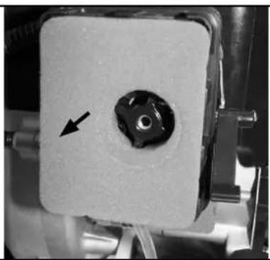
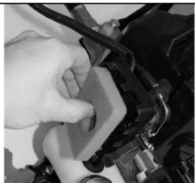
- Unclip the air filter cover and remove the sponge filter element.
- To avoid objects falling into the air tank, replace the air filter cover.
- Wash the filter element in warm soap water, rinse and allow drying naturally.
Important: Never clean the air filter with petrol or inflammable solvents.
⚠ Warning!
Never run the engine without the air filter element installed.
Lubricate angle transmission
Lubricate with lithium-based grease. Remove the screw and put in the grease, turning the shaft manually until grease emerges, then replace the screw.
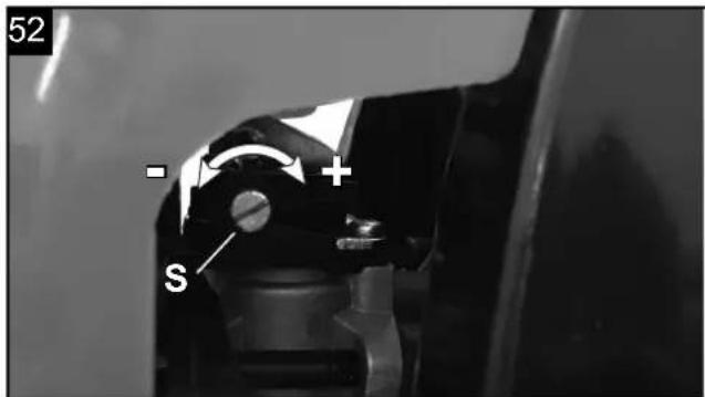
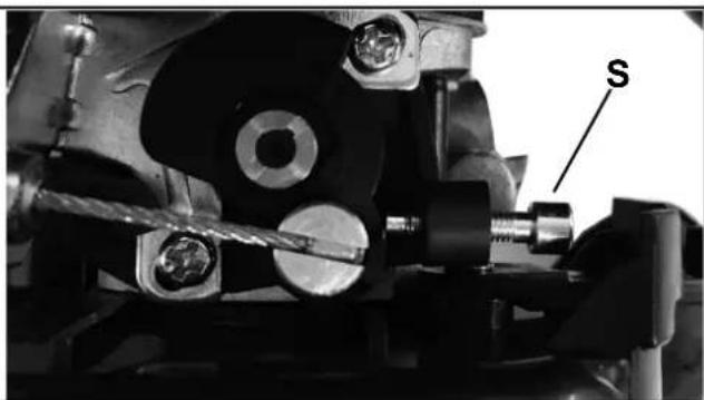
Adjusting the idle speed Fig. 52
If the cutting device runs idle, correct the idle speed.
- Allow the engine to warm for 3-5 minutes (No high speeds!).
- Turn the adjusting screw (S): clockwise
- idle speed increases (+) counterclockwise
- Idling speed decreases (-)
The idle speed is 3000 min-1
Contact the manufacturer if the cutter continues to run at idle.
Do not continue to operate the unit!
Storing the unit
After cutting, clean the unit thoroughly. Store the unit in a dry room allow the motor to cool down beforehand.
Important hint in case of sending the equipment to a service station:
Due to security reasons please see to it that the equipment is sent back free of oil and gas!
Ordering replacement parts
Please quote the following data when ordering replacement parts:
- Type of machine
• Article number of the machine
•
Service information
Please note that the following parts of this product are subject to normal or natural wear and that the following parts are therefore also required for use as consumables. Wear parts*: Line spool, cutting blade, spark plug, air filter
* Not necessarily included in the scope of delivery!
Replacement parts / accessories:
For the cutting equipment listed here, you can always use the safety guards provided with the unit.
Grass trimmer/brush cutter:
Spool with ∅ 450 7910700707
Blade with 2 teeth 7910700717
Blade with 3 teeth ∅ 255 x 1.4 7910700702
Transport guard for blade 3 teeth 3904801065
Blade with 4 teeth ∅ 255 x 1.5 7910700705
Transport guard for blade 4 teeth 3904801066
Blade with 8 teeth ∅ 255 x 1.5 7910700711
Transport guard for blade 8 teeth 3904801066
Safety shield for grass trimmer 3904803034
11. Storage
Cleaning
- Keep handles free of oil, so you always have a secure hold.
- Clean the equipment as required with a damp cloth and, if necessary, mild washing up liquid.
⚠️ Important!
- Always pull out the spark boot plug each time before carrying out any cleaning.
- Never immerse the equipment in water or other liquids in order to clean it.
- Store the chainsaw in a safe and dry place out of the reach of children.
Storage
Important: Never put the equipment into storage for longer than 30 days without carrying out the following steps.
Storing the equipment
If you intend to store the equipment for longer than 30 days, the equipment must be prepared accordingly. Otherwise the fuel still remaining in the carburetor will evaporate and leave a rubbery sediment. This can cause problems when starting up the equipment and may require expensive repairs.
1 Slowly remove the fuel tank cap to release any pressure that may have formed in the tank. Carefully empty the tank.
2 To remove the fuel from the carburetor, start the engine and let it run until the equipment stops.
3 Leave the engine to cool (approx. 5 minutes).
4 Remove the spark plug (see section 10 Change and clean the spark plug).
5 Add one teaspoon of 2-stroke engine oil into the combustion chamber. Slowly pull the starter cord several times to apply a layer of oil to all internal components. Fit the spark plug again.
Note: Store the equipment in a dry place and far away from possible ignition sources such as an oven, a gas-fi red hot water boiler, a gas-fi red dryer, etc.
Putting the equipment back into operation
1 Remove the spark plug (see section 10 Change and clean the spark plug).
2 Quickly tug on the starter cord to remove excess oil from the combustion chamber.
3 Clean the spark plug and check that the electrode gap is correct, or insert a new spark plug with the correct electrode gap.
4 Prepare the equipment for operation.
5 Fill the tank with the relevant mixture of fuel and oil. See the section „Fuel and oil“.
Transport
To transport the machine, empty the petrol tank as described in section 8 draining fuel. Clean coarse dirt
off the equipment with a brush or hand brush.
12. Disposal and recycling
The equipment is supplied in packaging to prevent it from being damaged in transit. The raw materials in this packaging can be reused or recycled. The equipment and its accessories are made of various types of material, such as metal and plastic. Defective components must be disposed of as special waste. Ask your dealer or your local council.
13. Troubleshooting
The table below contains a list of fault symptoms and explains what you can do to remedy the problem if your equipment fails to work properly. If the problem still persists after working through the list, please contact your nearest service workshop.
Important hint in case of sending the equipment to a service station:
Due to security reasons please see to it that the
equipment is sent back free of oil and gas!
| Fault Possible cause Remedy | ||
| The equipment does not start | Correct starting procedure not followedSooted or damp spark plugIncorrect carburetor settingBlade or nylon cutter mounted incorrectlyNo fuel in the tank | Follow the instructions for startingClean the spark plug or replace it with a new oneContact an authorized customer service outletReassemble the blade or nylon cutterCheck the fuel level |
| The equipment starts but does not develop its full power | Incorrect choke lever settingSoiled air fi IterIncorrect carburetor settingCutting blade blunt | Set the choke lever on the positionClean the air filterContact an authorized customer service outletHave cutting blade resharpened /replaced |
| The engine does not run smoothly | Incorrect electrode gap on the spark plugIncorrect carburetor setting | Clean the spark plug and adjust the electrode gap, or fi t a new spark plugContact an authorized customer service outlet |
| Engine smokes excessively | Incorrect fuel mixIncorrect carburetor setting | Use the correct fuel mix (see fuel mixing table)Contact an authorized customer service outlet |
| If the temperature of machines is too high | Engine is overloaded | Insure the machines have rest at regular time |
Table des matières:
Günzburger Straße 69
D-89335 Ichenhausen
CHER CLIENT,
7910702702 TRICORD
CE - Declaration of Conformity
Standard references:
EN ISO 11806-1:2011; EN ISO 11806-2:2011; EN ISO 14982:2009
This declaration of conformity is issued under the sole responsibility of the manufacturer.
Apparent defects must be notified within 8 days from the receipt of the goods. Otherwise, the buyer's rights of claim due to such defects are invalidated. We guarantee for our machines in case of proper treatment for the time of the statutory warranty period from delivery in such a way that we replace any machine part free of charge which provably becomes unusable due to faulty material or defects of fabrication within such period of time. With respect to parts not manufactured by us
we only warrant insofar as we are entitled to warranty claims against the upstream suppliers. The costs for the installation of the new parts shall be borne by the buyer. The cancellation of sale or the reduction of purchase price as well as any other claims for damages shall be excluded. The saw blade is a consumable item and explicitly excluded from any warranty.
Garantie FR


- Inhaltsverzeichnis:
- Seite:
- VEREHRTER KUNDE,
- Introduction
- MANUFACTURER:
- DEAR CUSTOMER,
- NOTE:
- WE RECOMMEND:
- Layout (Fig. 1)
- Scope of delivery
- Scope of delivery
- ⚠️ Important!
- Intended use
- Non-permitted users:
- Working hours for gasoline brush cutter
- Important information
- Safety instructions
- Training
- Preparation
- Operation
- Special safety warning
- Residual risks
- Technical data
- Before starting the equipment
- Fuel and oil
- Fuel mixing table
- Warning!
- Attachment and operation
- ASSEMBLY
- Mounting the shaft Fig. 51
- Assemble and disassemble the cutting head grass trimmer / nylon cutting head. Fig. 19 - 20
- Brush cutter / Cutter blade
- Assemble the safe guard. Fig. 21 23
- ⚠ Warning!
- Fit the belt. Fig. 25 - 29
- OPERATION
- Filling with fuel
- ⚠️ Risk of device damage!
- Draining fuel. Fig. 47
- Start on the unit
- ⚠ Danger of injury!
- Check before use!
- Start Fig. 30 - 34 + 48
- Working instructions
- Extending the cutting line
- Different cutting methods
- Trimming/mowing
- Low trimming
- Cutting along fences/foundations
- Trimming around trees
- Mowing
- Jamming
- Preventing recoil
- Maintenance
- Expert inspection is required:
- Replacing the line spool/cutting line Fig. 41 - 46
- Grinding the safety hood blade Fig. 24 (A)
- Grinding cutter blade (4)
- Change and clean the spark plug Fig. 35 - 36
- Clean the air filter Fig. 37 - 40
- Lubricate angle transmission
- Adjusting the idle speed Fig. 52
- Storing the unit
- Important hint in case of sending the equipment to a service station:
- Ordering replacement parts
- Service information
- Replacement parts / accessories:
- Storage
- Cleaning
- Storage
- Storing the equipment
- Putting the equipment back into operation
- Transport
- Disposal and recycling
- Troubleshooting
- Table des matières:
- CHER CLIENT,
- CE - Declaration of Conformity
- Standard references:
- Garantie FR
Brand : SCHEPPACH
Model : BCH5300BP
Category : String Trimmer