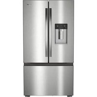
USER MANUAL WRFC5236RZ WHIRLPOOL
FRENCH DOOR BOTTOM MOUNT OWNER'S MANUAL
MANUEL D'UTILISATION DE RÉFRIGÉRATEUR À PORTE À DOUBLE BATTANT ET CONGÉLATEUR EN BAS
Table of Contents/Table des matières
REFRIGERATOR SAFETY....2
Refrigeration Safety....2
Proper Disposal of Your Old Refrigerator....3
REFRIGERATOR CARE 3
Cleaning 3
Changing the Lights 4
Refrigerator Shelves....5
Opening and Closing Doors 8
Vacation and Moving Care 8
INSTALLATION INSTRUCTIONS 9
Unpack the Refrigerator 9
Location Requirements 10
Electrical Requirements 11
Water Supply Requirements.... 11
Connect the Water Supply 11
Complete the Installation 13
Install Produce Preserver (available as an accessory only) ...
REFRIGERATOR FEATURES.... 14
Using the Controls 14
Internal Pantry Temperature Control (on some models) ......
External Pantry Temperature Control (only on 4 Door French
Door models) 16
Water and Ice Dispensers (on some models) 17
Ice Maker and Storage Bin.... 17
Water Filtration System 18
DOOR AND HANDLE INSTRUCTIONS 20
Door and Drawers.... 20
Remove and Replace Handles.... 20
Remove Refrigerator Doors and Hinges.... 21
Replace Refrigerator Doors and Hinges.... 23
Remove and Replace Refrigerator Drawer 23
Door Closing and Alignment 24
TROUBLESHOOTING.... 26
Refrigerator Operation 26
Temperature and Moisture 27
Ice and Water 27
PERFORMANCE DATA SHEET 29
Performance Data Sheet 29
SÉCURITÉ DU RÉFRIGÉRATEUR 34
Your safety and the safety of others are very important.
We have provided many important safety messages in this manual and on your appliance. Always read and obey all safety messages.

This is the safety alert symbol.
This symbol alerts you to potential hazards that can kill or hurt you and others.
All safety messages will follow the safety alert symbol and either the word "DANGER" or "WARNING." These words mean:
DANGER
WARNING
You can be killed or seriously injured if you don't immediately follow instructions.
You can be killed or seriously injured if you don't follow instructions.
All safety messages will tell you what the potential hazard is, tell you how to reduce the chance of injury, and tell you what can happen if the instructions are not followed.
IMPORTANT SAFETY INSTRUCTIONS
WARNING: To reduce the risk of fire, electric shock, or injury to persons when using your appliance, follow basic precautions, including the following:
■ Children should be supervised to ensure that they do not play with the appliance.
This appliance is not intended for use by persons (including children) with reduced physical, sensory, or mental capabilities, or lack of experience and knowledge, unless they have been given supervision or instruction concerning use of the appliance by a person responsible for their safety.
■ Do not use an extension cord.
If power supply cord is damaged, it must be replaced by manufacturer, its service agent, or a similarly qualified person in order to avoid a hazard.
■ Connect to potable water supply only.
■ This appliance is intended to be used in household and similar applications such as: staff kitchen areas in shops, offices, and other working environments; farm houses and by clients in hotels, motels, and other residential-type environments; bed and breakfast-type environments; and catering and similar non-retail applications.
■ Do not store explosive substances such as aerosol cans with a flammable propellant in this appliance.
■ Use the new hose-sets supplied with the appliance and that old hose-sets should not be reused.
Do not use replacement parts that have not been recommended by the manufacturer (e.g., parts made at home using a 3D printer).
- Keep ventilation openings, in the appliance enclosure or in the built-in structure, clear of obstruction.
■ Do not use mechanical devices or other means to accelerate the defrosting process, other than those recommended by the manufacturer.
■ Do not damage the refrigerant circuit.
■ Do not use electrical appliances inside the food storage compartments of the appliance, unless they are of the type recommended by the manufacturer.
■ Ice maker kit can be added to some models. See serial tag inside the food compartment of appliance for ice maker kit model information.
■ A qualified service technician must install the water line and ice maker. See installation instructions supplied with ice maker kit for complete details.
■ Do not locate multiple portable socket-outlets or portable power supplies at the rear of the appliance.
■ When positioning the appliance, ensure the supply cord is not trapped or damaged.
■ Do not locate multiple portable socket-outlets or portable power supplies at the rear of the appliance.
SAVE THESE INSTRUCTIONS
Proper Disposal of Your Old Refrigerator
WARNING
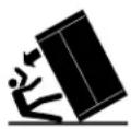
Tip Over Hazard
Refrigerator is top heavy and tips easily when not completely installed.
Keep doors taped closed until refrigerator is completely installed.
Use two or more people to move and install refrigerator
Failure to do so can result in death or serious injury.
REFRIGERATOR CARE Cleaning
WARNING
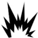
Explosion Hazard
Risk of Fire or Explosion.
Flammable Refrigerant Used.
Do Not Use Mechanical Devices to Defrost Refrigerator.
Do Not Puncture Refrigerant Tubing.
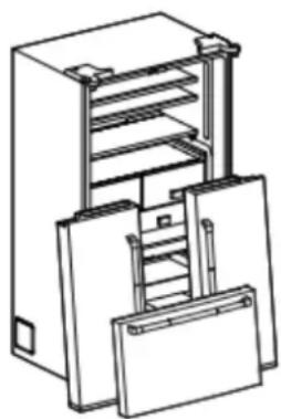
WARNING: Risk of child entrapment. Before you throw away your old refrigerator or freezer:
■ Take off the doors.
■ Leave the shelves in place so that children may not easily climb inside.
WARNING
Suffocation Hazard
Remove doors or lid from your old appliance.
Failure to do so can result in death or brain damage.
IMPORTANT: Child entrapment and suffocation are not problem of the past. Junked or abandoned refrigerators are still dangerous even if they will sit for "just a few days." If you are getting rid your old refrigerator, please follow these instructions to help prevent accidents.
Important information to know about disposal of refrigerants
Dispose of refrigerator in accordance with federal and local regulations. Refrigerants must be evacuated by a licensed, EPA certified refrigerant technician in accordance with established procedures.
natural_image
Technical line drawing of a multi-tiered mechanical device with internal compartments and mounting base (no text or symbols)
Both the refrigerator and freezer sections defrost automatically. However, clean both sections about once a month to avoid odor buildup. Wipe up spills immediately.
IMPORTANT:
Because air circulates between all sections, any odors formed in one section will transfer to the other. You must thoroughly clean all sections to eliminate odors. To avoid odor transfer and drying out of food, wrap or cover foods tightly.
- Do not use abrasive or harsh cleaners such as window sprays, scouring cleansers, flammable fluids, muriatic acid, cleaning waxes, concentrated detergents, bleaches or cleansers containing petroleum products on doors and cabinet, plastic parts, interior and door liners or gaskets. Do not use paper towels, scouring pads, or other harsh cleaning tools.
- For stainless steel models, stainless steel is corrosionous resistant and not corrosion-proof. To help avoid corrosion of your stainless steel, keep your surfaces clean by using the following cleaning instructions.
Cleaning the Touch Screen Display on the Dispenser Panel/Door (on some models):
A1. Make sure the refrigerator is unplugged or the power is disconnected before wiping the screen to avoid unintentionally changing the settings.
-
Mix a solution of mild detergent in warm water. Dampen a soft lint-free cloth with the solution and gently wipe the screen.
NOTE: Do not spray or wipe liquids directly onto the screen o over-saturate the cloth.
-
Plug in the refrigerator or reconnect power.
Cleaning the Interior:
IMPORTANT: Refrigerator shelves with under-shelf, LED lighting are not dishwasher safe.
- Unplug the refrigerator or disconnect power.
- Hand wash, rinse, and dry removable parts and interior surfaces thoroughly. Use a clean sponge or soft cloth and a mild detergent in warm water.
- Plug in the refrigerator or reconnect power.
Cleaning the Exterior:
IMPORTANT: Damage to smooth finish due to improper use of cleaning products or using non-recommended cleaning products is not covered under the warranty. Sharp or blunt instruments mar the finish.
- Unplug the refrigerator or disconnect power.
- Using a clean sponge or soft cloth and a mild detergent in warm water, wash, rinse, and thoroughly dry stainless steel and painted metal exteriors.
To keep your stainless steel refrigerator looking like new air to remove minor scuffs or marks, it is suggested that you the manufacturer's approved stainless steel cleaner and polish. This cleaner is for stainless steel parts only. Refer the Quick Start Guide for ordering information.
NOTE: When cleaning stainless steel, always wipe in the direction of the grain to avoid cross-grain scratching.
Do not allow the stainless steel cleaner and polish to come into contact with any plastic parts such as the trim pieces, dispenser covers, or door gaskets. If unintentional contact does occur, clean plastic part with a sponge and mild detergent in warm water. Dry thoroughly with a soft cloth.
3. Plug in refrigerator or reconnect power.
Style 1: Smooth Door/Painted Metal
| DO USE DO NOT USE | |
| ■ Soft, clean cloth ■ Abrasive cloths■ Paper towels or newsprint■ Steel-wool pads | |
| ■ Warm, soapy water with a mild detergent | ■ Abrasive powders or liquids■ Window sprays■ Ammonia■ Acidic or vinegar-based cleaners■ Oven cleaners■ Flammable fluids |
NOTE: Paper towels scratch and may dull the clear coat of the painted door. To avoid possible damage, use only soft, clean cloths to polish and wipe the door.
Style 2: Stainless Steel
| DO USE DO NOT USE | |
| ■ Soft, clean cloth ■ Abrasive cloths■ Paper towels or newsprint■ Steel-wool pads | |
| ■ Warm, soapy water with mild detergent | ■ Abrasive powders or liquids■ Ammonia■ Citrus-based cleaners■ Acidic or vinegar-based cleaners■ Oven cleaners |
| DO USE DO NOT USE | |
| ■ For heavy soil, use only a will manufacturer's approved stainless steel cleaner and polish | ■ Abrasive powders or liquids■ Ammonia■ Citrus-based cleaners■ Acidic or vinegar-based cleaners■ Oven cleaners■ Abrasive cloths■ Paper towels or newsprint■ Steel-wool pads |
| nd use |
NOTES:
If unintentional contact does occur, clean plastic part with a sponge and mild detergent in warm water. Dry thoroughly with a soft cloth.
Avoid exposing stainless steel appliances to caustic or corrosive elements such as high-salt, high-moisture, or high-humidity environments. Damage due to exposure to these elements is not covered under the warranty.
■ Just because a cleaner is a liquid does not mean it is nonabrasive. Many liquid cleansers formulated to be gentle on tile and smooth surfaces still damage stainless steel.
■ When cleaning stainless steel, always wipe in the direction of the grain to avoid cross-grain scratching.
■ Citric acid permanently discolors stainless steel. To avoid damaging the finish of your stainless steel refrigerator:
Do not allow these substances to remain on the finish:
- Mustard
- Citrus-based sauces
- Tomato juice
- Citrus-based products
- Marinara sauce
Condenser Cleaning
| AWARNING |
 |
| Explosion HazardRisk of Fire or Explosion due to Puncture of Refrig Tubing;Follow Handling Instructions Carefully.Flammable Refrigerant Used. |
There is no need for routine condenser cleaning in normal home operating environments. If the environment is particularly greasy or dusty or there is significant pet traffic in the home, the condenser should be cleaned every 6 months to ensure maximum efficiency.
If you need to clean the condenser, please call for service.
Changing the Lights
IMPORTANT: The LED lights in both the refrigerator and freezer compartments use LED technology. If the lights do not illuminate when the door or drawer is opened, call for assistance or service. Refer to the "Quick Start Guide" for contact information.
Refrigerator Shelves
Important information to know about glass shelves and covers:
Do not clean glass shelves or covers with warm water when are cold. Shelves and covers may break if exposed to sudden temperature changes or impact, such as bumping. Tempered glass is designed to shatter into many small, pebble-size piec
This is normal. Glass shelves and covers are heavy. Use both hands when removing them to avoid dropping.
The shelves in your refrigerator are adjustable to match your individual storage needs.
Storing similar food items together in your refrigerator and adjusting the shelves to fit different heights of items will make finding the exact item you want easier. It will also reduce the amount of time the refrigerator door is open, and save energy.
Full-Width Shelf (on some models)
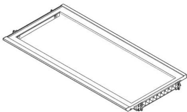
To remove and replace the Full width shelf:
- Remove items from the shelf.
- Lift the shelf gently using both hands until it is out of the side supports.
- Slide the shelf gently out of the Refrigerator. Do not let the shelf touch the side walls of the Refrigerator or the doors.
natural_image
Isometric line drawing of a rectangular frame with internal truss structure (no text or symbols)
Half-Width Shelf (on some models)
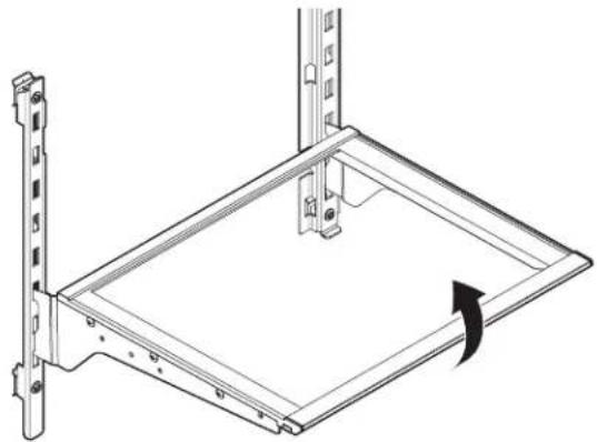
To remove and replace a half width shelf:
- Remove items from the shelf.
- Tilt the front of the shelf up. Lift the shelf out of the shelf supports.
- Reinstall the shelf by guiding the rear shelf hooks into the shelf supports. Tilt the front of the shelf up until the rear shelf hooks go into the shelf supports.
- Lower the front of the shelf. Make sure the shelf is in the correct position.
natural_image
Technical line drawing of a metal frame assembly with mounting bracket and rotation arrow (no text or symbols)
Nesting Shelf (On some models)
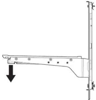
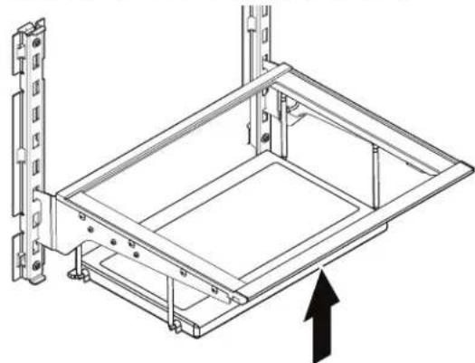
This shelf will expand creating an additional storage area under the shelf.
To expand the shelf: they
Pull down the lower part of the shelf using your fingers until is complete down the lower part of the shelf.
natural_image
Technical line drawing of a mechanical lever or bracket with a downward arrow indicating force or motion (no text or symbols present)
To contract/close the shelf:
- Remove any food item placed in the lower surface.
- Push up the lower part of the shelf using your fingers until is folded back and secured together with the main shelf body.
- There is a magnet to keep shelf secured in the upper position, the shelf will be secured in place by itself.
natural_image
Technical line drawing of a mechanical assembly with mounting brackets and a central frame (no text or symbols)
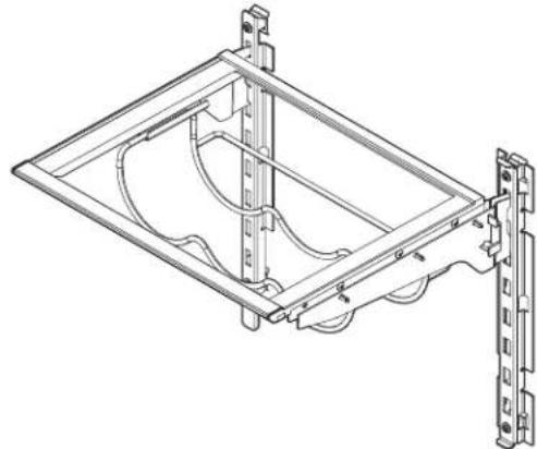
Wine Rack (on some models)
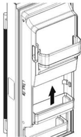
Refrigerator Door Bins
Under one shelf, there are brackets installed to the supports (the bins on your refrigerator door are adjustable to meet your bracket on each support). The wine rack rests in these brackets: individual storage needs.
To remove and replace the wine rack:
- Remove the wine rack by lifting it up off the brackets. Press the right-hand side of the rack inward until it is free of its bracket. Lower the right-hand side slightly and disengage the left-hand side from its bracket.
- Replace the wine rack by inserting the left-hand side into its bracket. Press inward on the right-hand side until it will slide past the bracket edge and set it into its bracket.
natural_image
Technical line drawing of a mechanical frame assembly with mounting brackets (no text or symbols)
natural_image
Technical line drawing of a door panel with an arrow indicating direction (no text or symbols present)
Crisper and Pantry Drawers
To remove and replace the drawers:
- Grasp the handle at the bottom of the drawer and slide the drawer straight out to the stop. Lift the drawer off the bottom guide.
- Replace the drawer by placing it on the bottom drawer guide and pushing it past the drawer stop into position.
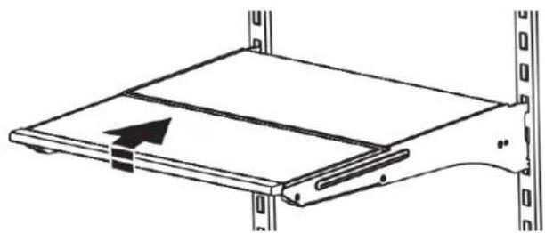
Tuck/Slide Away Shelf (on some models)
Some shelves will tuck/slide away to create room for taller objects.
To retract and extend the front section of the shelf:
- To retract the front-section of the shelf, slightly lift up on the front edge and push the adjustable portion of the shelf back toward the rear of the refrigerator.
- Extend the front of the shelf by pulling the retracted portion of the shelf outward until it is fully extended.
natural_image
Diagram of a mechanical assembly with a rectangular plate and vertical supports, no text or symbols present
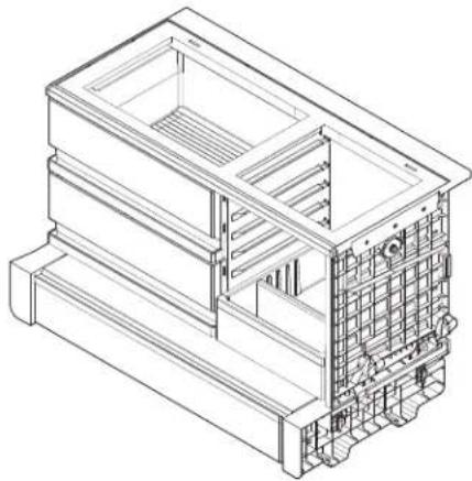
natural_image
Isometric line drawing of a multi-level industrial or construction structure with internal compartments and structural elements (no text or symbols)
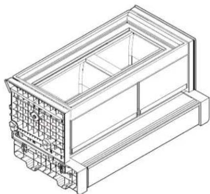
natural_image
Isometric line drawing of a rectangular electronic device with internal components and mounting brackets (no text or symbols)
Pull Out Tray (available on some models)
To remove and replace the pull-out tray:
- Pull the tray to the fully open position or when it stops.
- Lift up and out of gliders or rollers toward the front of the refrigerator.
- Replace the tray by placing it on the bottom tray guide and pushing it past the tray stop into position.
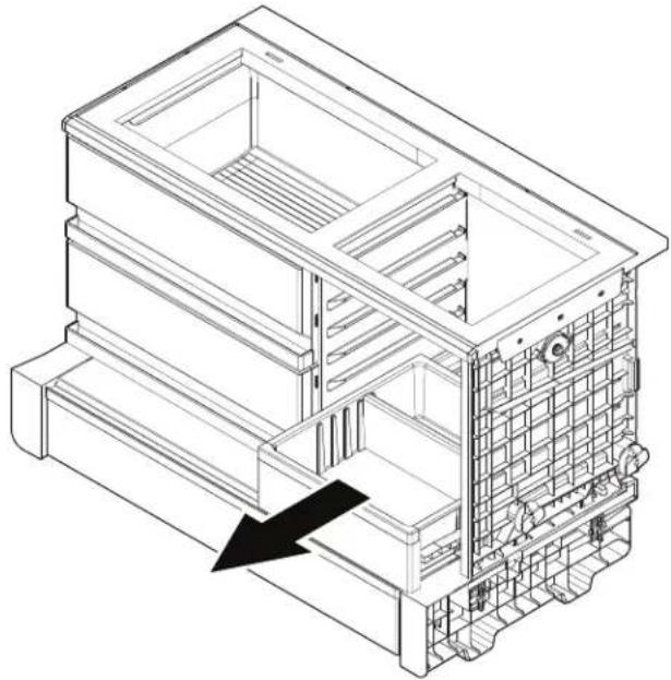
natural_image
Isometric line drawing of a multi-story building interior with structural details and a black arrow indicating a location or feature (no text or symbols present)
To remove or replace pull out tray divider:
- The tray divider can be removed or replaced in different positions.
- Lift the divider to remove it from the locating ribs.

A. Divider
B. Pull out tray
- Put the divider in the new position. Push the divider down until it is secure.
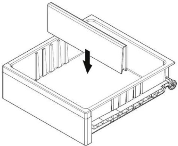
natural_image
Isometric line drawing of a mechanical device with internal components and a downward arrow indicating force or movement (no text or symbols)
A. Divider
B. Pull out tray
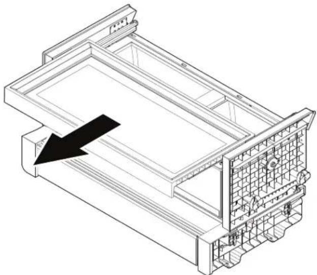
Pull Out Tray (available on some models):
To remove and replace the pull-out tray:
- Pull the tray to the fully open position or when it stops.
- Lift up and out of gliders or rollers toward the front of the refrigerator.
- Replace the tray by placing it on the bottom tray guide and pushing it past the tray stop into position.
natural_image
Technical line drawing of a mechanical assembly with no visible text or symbols
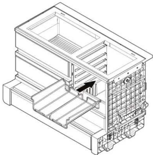
Pull Out Tray Can Rack (available for some models as accessory only):
To remove and replace the pull out tray can rack:
- The crisper tray has supports on its side walls for the can rac
-
Put the can rack on the side supports.
-
Make sure the can rack is secure. You can now put cans The refrigerator compartment door switch is located in the top left and right hinge cover. The freezer compartment door switch is
natural_image
Technical line drawing of a multi-level industrial or mechanical assembly with internal components and a black arrow indicating a specific section (no text or symbols present)
Crisper(s) Cover
To Remove the Crisper(s) Cover:
- Remove the crisper pan, platter pocket, and crisper glass before removing the crisper.
- Hold the glass, insert firmly with one hand, and press up center of the glass insert until it rises above the plastic Slowly slide the glass insert forward to remove.
- Lift the cover frame and remove it.
To replace crisper(s) cover:
- Fit the back of the cover frame into the supports on the six walls of the refrigerator. Lower the front of the cover frame place.
- Slide the rear of the glass insert into the cover frame and lower the front into place.
Opening and Closing Doors
There are two refrigerator compartment doors. The doors can be opened and closed either separately or together. On some models, there is a, automatic closing mechanism so the door(s) will not unintentionally be left open. If a door is open at a 40° smaller angle, the door will automatically, softly close.
There is a vertically-hinged seal on the left refrigerator door.
■ When the left-hand door is opened, the hinged seal automatically folds inward so that it is out of the way.
■ When both doors are closed, the hinged seal automatically forms a seal between the two doors.

natural_image
Technical line drawing of a door with handle and internal structure, labeled 'A' (no text or symbols beyond label)
A. Hinged seal
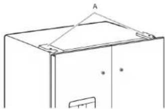
The refrigerator compartment door switch is located in the top left and right hinge cover. The freezer compartment door switch is located in the right side of freezer side adapter.
■ The door switch uses magnet to sense door opening/closing.
■ Ensure there are no magnet or electronic devices (Speaker, CoolVox ^® , etc) within 3 inches of the hinge cap and freezer right side adapter.
NOTE: The light and internal user interface (UI) will not turn on if the door opening is not detected.
natural_image
Simple line drawing of a cabinet or enclosure with a triangular roof and door (no text or symbols)
A. Hinged cover
Vacation and Moving Care
Vacation mode
If You Choose to Leave the Refrigerator On While You're Away:
-
Use up any perishables and freeze other items.
in. the your refrigerator has an automatic ice maker, and is am connected to the household water supply, turn off the water supply to the refrigerator. Property damage can occur if the water supply is not turned off.
-
If you have an automatic ice maker, turn off the ice maker.
side NOTE: Depending on your model, automatic ice maker might be located in the freezer compartment and/or in the refrigerator left door.
■ To turn off the ice maker in the freezer compartment, press Off switch.
■ To turn off automatic ice maker in refrigerator door, turn it off using HMI. See "Water and Ice Dispensers."
- Empty the ice bin.
Models with Vacation Mode Feature
■ Turn on Vacation mode. See the "Quick Start Guide" for details.
NOTE: Activating Vacation mode does not turn off the ice maker.
If You Choose to Turn Off the Refrigerator Before You Leave
- Remove all food from the refrigerator.
-
If your refrigerator has an automatic ice maker:
■ Turn off the water supply to the ice maker at least one day ahead of time.
■ When the last load of ice drops, press the switch to OFF position, either on the ice maker or UI control, depending on your model.
-
Empty the ice bin.
- Turn off the Temperature control(s). See the "Quick Start Guide."
- Clean refrigerator, wipe it, and dry well.
- Tape rubber or wood blocks to the tops of both doors to prop them open far enough for air to get in. This stops odor and mold from building up.
Moving
When you are moving your refrigerator to a new home, follow these steps to prepare it for the move.
- If your refrigerator has an automatic ice maker:
■ Turn off the water supply to the ice maker at least one ahead of time.
■ Disconnect the water line from the back of the refrigerator.
■ When the last load of ice drops, press the switch to OFF position, either on the ice maker or UI control, depending on your model.
- Remove all food from the refrigerator and freezer.
- Empty the ice bin.
- Turn off the Temperature control(s). See the "Quick Start Guide."
- Unplug refrigerator.
- Clean, wipe, and dry thoroughly.
- Take out all removable parts, wrap them well, and tape the together so they don't shift and rattle during the move.
- Depending on the model, raise the front of the refrigerator rolls more easily or raise the leveling screws so they don't scrape the floor. See "Adjust the Door(s)" or "Door Closing Door Alignment."
- Tape the doors closed and tape the power cord to the back the refrigerator.
When you get to your new home, put everything back and refer the "Installation Instructions" section for preparation instructions. Also, if your refrigerator has an automatic ice maker, remember reconnect the water supply to the refrigerator.
Sabbath Mode
Your refrigerator is equipped with the Sabbath Mode feature, which is designed for those whose religious observances require turning off the lights and ice maker.
By selecting this feature:
■ The temperature set points and Deli Pan settings remain unchanged.
■ LEDs from the electronic controls will not display.
■ The Sabbath button will be the only light displaying.
■ Ice and Water will not dispense.
■ No alarm will ring.
■ Interior lights will turn off.
■ The product will not change its behavior by opening the d
For most efficient refrigerator operation, it is recommended to Sabbath mode when it is no longer required.
To fully activate Sabbath Mode, you must follow the instruction below for the control panel.
IMPORTANT: If you do not activate Sabbath Mode in both ways listed below, some functions you wish to disable will remain active.
CONTROL PANEL
In Sabbath Mode, the temperature set points remain unchanged and the interior lights turn off.
- To turn ON the Sabbath Mode, Press the Sabbath button on the dispensing or internal controls and hold for 3 seconds.
- Press the Sabbath button again for 3 seconds to turn OFF Sabbath Mode. Turn Ice Maker back ON.
NOTE: If a power outage occurs while in Sabbath Mode the appliance will remain in Sabbath Mode when power returns.
INSTALLATION INSTRUCTIONS
Unpack the Refrigerator
WARNING
Excessive Weight Hazard
Use two or more people to move and install or uninstall appliance.
Failure to do so can result in back or other injury.
Refrigerator Delivery
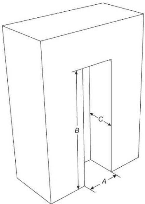
A minimum door opening of 30" (762 mm) is required. If door opening is 36" (914 mm) or less, then removal of doors, drawer, and hinges is required.
Cart the refrigerator from the side for all door openings.
Remove the Packaging
The product is in the cardboard box. It has written instructions how to unpack the refrigerator. Follow these instructions.
■ Remove tape and glue residue from surfaces before turning on the refrigerator. Rub a small amount of liquid dish soap over the adhesive with your fingers. Wipe with warm water and dry.
■ Do not use sharp instruments, rubbing alcohol, flammable fluids, or abrasive cleaners to remove tape or glue. These products can damage the surface of your refrigerator. For more information, see "Refrigerator Safety."
■ Dispose of/recycle all packaging materials.
When Moving Your Refrigerator:
Your refrigerator is heavy. When moving the refrigerator for cleaning or service, be sure to cover the floor with cardboard or hardboard to avoid floor damage. Always pull the refrigerator straight out when moving it. Do not wiggle or "walk" the refrigerator when trying to move it, as floor damage could occur.
Clean Before Using
After you remove all of the packaging materials, clean the inside of your refrigerator before using it. See the cleaning instructions in "Refrigerator Care."
Do not clean glass shelves or covers with warm water when they exist cold. Shelves and covers may break if exposed to sudden temperature changes or impact, such as bumping. Tempered glass is designed to shatter into many small, pebble-size pieces. This is normal. Glass shelves and covers are heavy. Use both hands when removing them to avoid dropping.
Location Requirements
WARNING
Explosion Hazard
Keep flammable materials and vapors, such as gasoline, away from appliance.
Use nonflammable cleaner.
Failure to do so can result in death, explosion, or fire.
IMPORTANT: This appliance is intended to be used indoor for household and similar applications such as:
■ Farm houses and by clients in hotels, motels and other residential type environments.
■ Bed and breakfast type environments.
■ Catering and similar non-retail applications.
NOTE: If the manufacturer wants to limit the use of the appliance to less than the above, this has to be clearly stated in the instructions.
To ensure proper ventilation for your refrigerator, allow for 3/16 (4.8 mm) of space on each side and 1/4" (6.4 mm) at the to Allow for 1" (25.4 mm) of space behind the refrigerator. If you refrigerator has an ice maker, allow extra space at the back f water line connections. When installing your refrigerator next to fixed wall, leave 14 "3 (95 mm) minimum space between the refrigerator and wall to allow for the door to swing open.
NOTE: This refrigerator is intended for use in a location where temperature ranges from a minimum of 50°F (10°C) to a maximum of 110°F (43°C). The preferred room temperature range for optimum performance, which reduces electricity usage and provides superior cooling, is between 60°F (15°C) and 90°F (32°C). It is recommended that you do not install the refrigerator near a heat source, such as an oven or radiator.
natural_image
Isometric line drawing of a rectangular prism with internal door and labeled dimensions A, B, C (no text or symbols beyond labels)
| SKU | Width (A) | Height (B) Depth (C) |
| KRFC236S*;WREC3036R*;WRFC5036R*;WRFC5236R*;WRMC5036R*;WRMC7036R*;WRFC7036R*;KRFC636S*;KRFC536S* | 36"(914.6 mm) | 70^3/_16 "(1782.4 mm) |
| KRFC336S*;JFFCCI72S*;KRFC936S*;KRFC736S*;JFFCCE72S* | 72^1/_8 "(1832.4 mm) |
Electrical Requirements
WARNING
Electrical Shock Hazard
Plug into a grounded 3 prong outlet.
Do not remove ground prong.
Do not use an adapter.
Do not use an extension cord.
Failure to follow these instructions can result in death, fire, or electrical shock.
Before you move your refrigerator into its final location, it is important to make sure you have the proper electrical connec
If the supply cord is damaged, it must be replaced by the manufacturer or its service agent or a similarly qualified person. Do not use a cord that shows cracks or abrasion damage along length or at either the plug or connector end.
Recommended Grounding Method
A 115 V, 60 Hz AC-only 15 A or 20 A fused, grounded elect supply is required. It is recommended that a separate circuit serving only your refrigerator and approved accessories be provided. Use an outlet that cannot be turned off by a switch, not use an extension cord.
IMPORTANT: If this product is connected to a GFCI (Ground Circuit Interrupter) protected outlet, nuisance tripping of the power supply may occur, resulting in loss of cooling. Food quality and flavor may be affected. If nuisance tripping has occurred, and if the condition of the food appears poor, dispose of the food.
NOTE: Before performing any type of installation or cleaning, disconnect the refrigerator from the electrical source. When you are finished, reconnect the refrigerator to the electrical source set to the desired setting. See the "Quick Start Guide".
Water Supply Requirements
Gather the required tools and parts before starting installation. Read and follow the instructions provided with any tools listed here.
■ Flat-blade screwdriver
■ 1/4" Nut driver
■ 7/16" and 1/2" Open-end or adjustable wrenches
v☐ 1/4" Drill bit
■ Cordless drill
■ Connect to potable water supply only.
Do not use with water that is microbiologically unsafe or of unknown quality without adequate disinfection before or after the system. Systems certified for cyst reduction may be used on disinfected waters that may contain filterable cysts.
■ All installations must meet local plumbing code requirements.
■ Do not use a piercing-type or 3/16" (4.76 mm) saddle valve which reduces water flow and clogs more easily.
■ Use copper or PEX tubing and check for leaks. Install copper or PEX tubing only in areas where the household temperature will remain above freezing.
■ For models with water filters, the disposable water filter should be replaced at least every 6 months.
Water Pressure
A cold water supply with water pressure of between 20 psi and 145 psi (138 kPa and 1000 kPa) is required to operate the water dispenser and ice maker. If you have questions about your water pressure, call a licensed, qualified plumber.
NOTE: If the water pressure is less than what is required, the flo of water from the water dispenser could decrease or ice cubes could be hollow or irregular shaped.
Reverse Osmosis Water Supply
IMPORTANT: The pressure of the water supply coming out of a reverse osmosis system going to the water inlet valve of the refrigerator needs to be between 20 psi and 145 psi (138 kPa and 1000 kPa).
If a reverse osmosis water filtration system is connected to your cold water supply, the water pressure to the reverse osmosis system needs to be a minimum of 40 psi to 60 psi (276 kPa to 414 kPa).
If the water pressure to the reverse osmosis system is less than 40 psi to 60 psi (276 kPa to 414 kPa):
Check to see whether the sediment filter in the reverse osmosis system is blocked. Replace the filter if necessary.
Allow the storage tank on the reverse osmosis system to refill after heavy usage. The tank capacity could be too small to keep up with the requirements of the refrigerator.
NOTE: Faucet-mounted reverse osmosis systems are not recommended.
If your refrigerator has a water filter, it may further reduce the water pressure when used in conjunction with a reverse D80smosis system. Remove the water filter. See "Filters And Accessories."
Fault
If you have questions about your water pressure, call a licensed,
qualified plumber.
Connect the Water Supply
Read all directions before you begin.
IMPORTANT:
and Plumbing shall be installed in accordance with the International Plumbing Code and any local codes and ordinances.
■ The gray water tubing on the back of the refrigerator (which is used to connect to the household water line) is a PEX (cross-linked polyethylene) tube. Copper and PEX tubing connections from the household water line to the refrigerator are acceptable, and will help avoid off-taste or odor in your ice or water. Check for leaks. If PEX tubing is used instead of copper, we recommend the following part numbers: W10505928RP (7 ft [2.14 m] jacketed PEX), 8212547RP (5 ft [1.52 m] PEX), or W10267701RP (25 ft [7.62 m] PEX).
■ Install tubing only in areas where temperatures will remain above freezing.
■ Connect to a potable water supply only.
ed Do not use with water that is microbiologically unsafe or of unknown quality without adequate disinfection before or after the system. Systems certified for cyst reduction may be used on disinfected waters that may contain filterable cysts.
Gather the required tools and parts before starting installation.
■ Flat-blade screwdriver
■ 7/16" and 1/2" Open-end or adjustable wrenches
■ 1/4" Nut driver
v☐ 1/4" Drill bit
■ Cordless drill
NOTE: Your refrigerator dealer has a kit available with a 1/4" (6.35 mm) saddle-type shut-off valve, a union, and copper or tubing. Before purchasing, make sure a saddle-type valve complies with your local plumbing codes. Do not use a piercing-type or 3/16" (4.76 mm) saddle valve which reduces water flow and clogs more easily.
Connect to Water Line
IMPORTANT: If you turn on the refrigerator before the water connected, turn off the ice maker.
- Unplug refrigerator or disconnect power.
- Turn off main water supply. Turn on nearest faucet long enough to clear line of water.
- Use a quarter-turn shut-off valve or the equivalent, served by a 1/2" copper or PEX household supply line.
NOTE: To allow sufficient water flow to the refrigerator, a minimum 1/2" size copper or PEX household supply line is recommended.
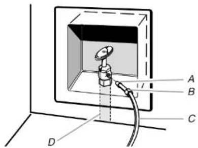
A. Bulb
C. Copper or PEX tubing (to refrigerator)
B. Nut
D. Household supply line (1/2" minimum)
- Now you are ready to connect the copper or PEX tubing to shut-off valve. Use 1/4" (6.35 mm) O.D. (Outside Diameter) soft copper or PEX tubing to connect the shut-off valve and the refrigerator.
■ Ensure that you have the proper length needed for the job. Be sure both ends of the copper tubing are cut square 3
- Slip compression sleeve and compression nut onto copper tubing as shown. (PEX tubing has compression sleeves and compression nuts preinstalled.) Insert end of tubing into outlet end squarely as far as it will go. Screw compression nut onto outlet end with adjustable wrench. Do not overtighten.

A. Compression sleeve
C. Copper or PEX tubing
B. Compression nut
- Place the free end of the tubing into a container or sink, and turn on main water supply to flush out tubing until water is clear. Turn off shut-off valve on the water pipe.
NOTE: Always drain the water line before making the final 5. connection to the inlet of the water valve, to avoid possible 6. water valve malfunction.
- Bend the copper or PEX tubing to meet the water line inlet, which is located on the back of the refrigerator cabinet. Leave a coil of copper or PEX tubing to allow the refrigerator to be pulled out of the cabinet or away from the wall for service.
Connect to Refrigerator
Depending on your model, the water line may come down from the top or up from the bottom. Follow the connection instructions for your model.
Style 1
- Remove plastic cap from water valve inlet port. Attach the copper or PEX tube to the valve inlet using a compression nut and sleeve as shown. Tighten the compression nut. Do not overtighten. Confirm copper or PEX tubing is secure by pulling on tubing.
- Create a service loop with the copper tubing. Avoid kinks when coiling the tubing. Secure copper or PEX tubing to refrigerator cabinet with a "P" clamp.
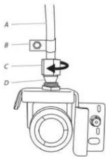
A. Copper or PEX tubing
B. "P" clamp
C. Compression nut
D. Compression sleeve
- Turn on water supply to refrigerator and check for leaks. Correct any leaks.
- If ice is desired, turn on the ice maker.
NOTE: Allow 24 hours to produce the first batch of ice. Discard the first three batches of ice produced. Allow three days to completely fill the ice storage bin.
to the Style 2
- Unplug refrigerator or disconnect power.
- Remove and discard the short, black plastic part from the end job of the water line inlet.
- Thread the nut onto the end of the tubing. Tighten the nut by hand. Then tighten it with a wrench two more turns. Do not overtighten.
NOTE: To avoid rattling, be sure the copper tubing does not touch the cabinet's side wall or other parts inside the cabinet.
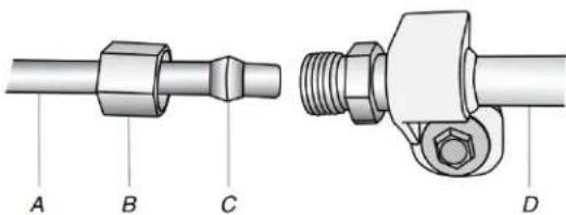
A. Household water line C. Ferrule (purchased)
B. Nut (purchased) D. Refrigerator water tubing
-
Install the water supply tube clamp around the water supply line to reduce strain on the coupling.
-
Turn shut-off valve on.
-
Check for leaks. Tighten any connections (including connections at the valve) or nuts that leak.
-
On some models, the ice maker is equipped with a built-in water strainer. If your water conditions require a second water strainer, install in the 1/4" (6.35 mm) water line at either tube connection. Obtain a water strainer from your appliance dealer.
Complete the Installation
WARNING
Electrical Shock Hazard
Plug into a grounded 3 prong outlet.
Do not remove ground prong.
Do not use an adapter.
Do not use an extension cord.
Failure to follow these instructions can result in death, fire, or electrical shock.
- Plug into a grounded 3 prong outlet.
NOTE: Allow 24 hours to produce the first batch of ice. Discard the first three batches of ice produced. Allow 3 completely fill the ice storage bin.
- Flush the water system. See "Water and Ice Dispensers."
Install Produce Preserver (available as an accessory only)
Your refrigerator's accessory packet includes a Produce Preserver, which should be installed prior to use. On some models, the Produce Preserver is already installed at the factory. To order a replacement produce preserver, use part number W10346771.
The Produce Preserver absorbs ethylene, allowing the ripening process of many produce items to slow down. As a result, certain produce items will stay fresh longer.
Ethylene production and sensitivity varies depending on the type of fruit or vegetable. To preserve freshness, it is best to separate produce with sensitivity to ethylene from fruits that produce 2. Moderate to high amounts of ethylene.
| Water tube | Sensitivity to Ethylene | Ethylene Production |
| Apples High Very High | | |
| Asparagus Medium Very Low | | |
| Berries Low Low | | |
| Broccoli High Very Low | | |
| Cantaloupe Medium High | | |
| Carrots Low | Very Low | |
| Citrus Fruit Medium Very Low | | |
| Grapes Low | Very Low | |
| Lettuce High Very Low | | |
| Pears High Very High | | |
| Spinach High Very Low | | |
Installing the Produce Preserver
CAUTION: IRRITANT MAY IRRITATE EYES AND SKIN.
DANGEROUS FUMES FORM WHEN MIXED WITH OTHER
PRODUCTS.
Do not mix with cleaning products containing ammonia, bleach, or acids. Do not get in eyes, on skin or clothing. Do not breathe dust to keep out of reach of children.
FIRST AID TREATMENT: Contains potassium permanganate. If swallowed, call a Poison Control Center or doctor immediately. Do not induce vomiting. If in eyes, rinse with water for 15 minutes. If on skin, rinse with water.
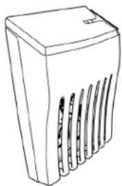
Style 1-Located Inside the Refrigerator:
- Find the Produce Preserver housing inside the refrigerator.
natural_image
Line drawing of a rectangular electronic device with ventilation slots and a lid (no text or symbols)
- Lift up on the housing to remove it from the mounting tab.
- Open the housing by pulling up and out on the back of the to of the housing.
- Remove the Produce Preserver pouches from the packaging. Place them into the housing then snap housing back together.
NOTE: For best performance, always use two pouches.
- Adhere the Produce Preserver housing to the back wall of the crisper drawer according to the instructions included in the package.
- Place housing back on mounting tab.
Style 2-Located in Crisper or Refrigerator Drawers:
For your convenience, the suction-mounted produce preserver can be installed in either the crisper or the refrigerated drawers.
- Wash the interior of a drawer with a solution of mild dish soap and warm water and dry thoroughly.
- Find the package containing the Produce Preserver inside the refrigerator and install the Produce Preserver into the drawer, according to the instructions provided in the package.
Installing the Status Indicator
The Produce Preserver comes with a status indicator, which should be activated and installed at the same time the pouch installed.
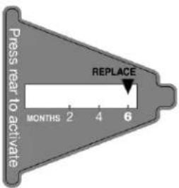
- Place the indicator facedown on a firm, flat surface.
- Apply pressure to the bubble on the back of the indicator, the bubble pops to activate the indicator.
- Slide open the cap on the Produce Preserver housing.
- Place the indicator in the top of the housing, facing outward
- Slide the cap closed, and check that the indicator is visible through the rectangular hole in the cap.
NOTE: The cap will not close easily if the indicator's rear bubble has not been popped.
Replacing the Produce Preserver Pouches
The disposable pouches should be replaced every 6 months, when the status indicator has completely changed from white to red.
To order replacements, see the contact information in the Quick Start Guide. Order part number W10346771A or FRESH1.
- Remove the used pouches from the produce preserver housing.
- Remove the used status indicator.
- Install the new pouches and status indicator using the instructions in the previous sections or instructions included the replacement packets.
REFRIGERATOR FEATURES
Using the Controls
WARNING
Electrical Shock Hazard
Plug into a grounded 3 prong outlet.
until Do not remove ground prong.
Do not use an adapter.
Do not use an extension cord.
Failure to follow these instructions can result in death, fire, or electrical shock.
WARNING
Explosion Hazard
Keep flammable materials and vapors, such as gasoline, away from appliance.
Use nonflammable cleaner.
Failure to do so can result in death, explosion, or fire.
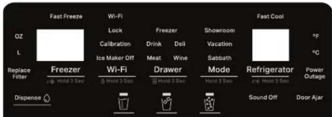
Turn Sound Notifications On/Off
This feature controls the audible notifications for the product.
To Turn Sound Notifications On/Off:
■ Press and hold the Cubed Ice and Crushed Ice buttons simultaneously for 3 seconds.
Change Water Dispense Volume Unit
This feature lets you change the unit for the water dispense volume display between ounces (oz) and liters (L).
The factory default unit for water dispense volume is ounces (oz).
To change from ounces (oz) to liters (L):
■ Press and hold the Mode button and the Refrigerator button at the same time for 3 seconds.
The water dispense volume unit display will change from oz to L.
Calibrate Measured Fill
Household water pressure may affect the accuracy of the Measured Fill feature. For optimum performance of your water dispenser, you must first calibrate Measured Fill.
NOTE: Flush the water system before you calibrate Measured
Calibration Procedure
- Place a measuring cup on the dispenser tray in the center front of the water dispenser paddle.
- Press and hold the water cup icon button for 3 seconds.
-
The system enters calibration mode. The Calibration icon illuminates and stays lit while you calibrate the Measured Fill feature.
-
Press and release the water dispenser paddle to dispense water to the cup fill line in the measuring cup.
NOTE: If the cup overfills or water spills, empty the cup. Press Back to start the calibration procedure again.
-
When you have dispensed 1 cup of water correctly, press the water cup icon button. This confirms the calibration.
-
When the calibration is confirmed, the icons will turn off. The display will return to the home screen.
Change Temperature Unit
This feature lets you change the displayed temperature unit between Fahrenheit (°F) and Celsius (°C).
The factory default temperature unit is Fahrenheit (°F).
To change from Fahrenheit (°F) to Celsius (°C):
■ Press and hold the Freezer button and the Mode button at the same time for 3 seconds.
The temperature unit display will change from ^ F to ^ C.
Showroom Mode
Showroom Mode turns off the cooling system in the product. The mode also stops the ice maker and the water dispenser.
NOTE: Do not use showroom mode for normal household use This mode is for retail display only. When showroom mode is active, the product will not cool, make ice, or dispense water.
To turn showroom mode On/Off:
■ Press and hold the Freezer button and the Refrigerator button at the same time for 3 seconds.
■ When Showroom Mode is active, the "Showroom" icon will light up.
■ When Showroom Mode is not active, the "Showroom" icon turn off.
Wi-Fi
Wi-Fi connectivity allows your Smart Refrigerator to connect to Internet and interact with the refrigerator from your smartphone mobile device. This connection opens up several Smart options you — options intended to save you valuable time and energy
■ Press the Wi-Fi button to activate the Wi-Fi feature.
Whirlpool App Installation and Setup:
- Download the Whirlpool app from your device's app store.
- Install the app.
- Open the app and follow the steps in the app to make a account.
- Follow the steps in the app to connect your appliance
NOTE: App features and functionality subject to change. Data charges can apply. Subject to Terms of Service available on website www.whirlpool.com/connect.
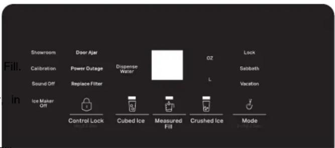
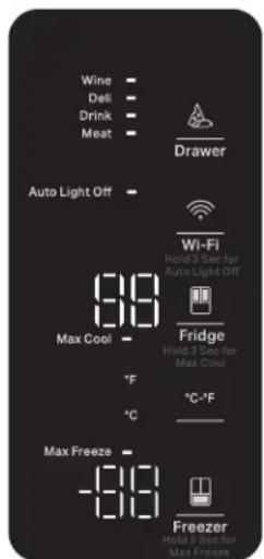
Turn Sound Notifications On/Off
This feature controls the audible notifications for the product.
To Turn Sound Notifications On/Off:
■ Press and hold the Cubed Ice and Mode buttons simultaneously for 3 seconds.
Change Water Dispense Volume Unit
This feature lets you change the unit for the water dispense volume display between ounces (oz) and liters (L).
The factory default unit for water dispense volume is ounces (oz).
To change from ounces (oz) to liters (L):
Will Press and hold the Mode button and the Crushed Ice button at the same time for 3 seconds.
The water dispense volume unit display will change from
theoz to L.
Calibrate Measured Fill
Household water pressure may affect the accuracy of the Measured Fill feature. For optimum performance of your water dispenser, you must first calibrate Measured Fill.
NOTE: Flush the water system before you calibrate Measured Fill.
Calibration Procedure
- Place a measuring cup on the dispenser tray in the center, in user front of the water dispenser paddle.
- Press and hold the Measure Fill button for 3 seconds.
- The system enters calibration mode. The Calibration icon illuminates and stays lit while you calibrate the Measured Fill feature.
- Press and release the water dispenser paddle to dispense water to the cup fill line in the measuring cup.
NOTE: If the cup overfills or water spills, empty the cup. Pres Back to start the calibration procedure again.
-
When you have dispensed 1 cup of water correctly, press the Measure Fill button. This confirms the calibration.
-
After the Measure Fill calibration is confirmed, the icons will turn off. The display will return to the home screen.
Change Temperature Unit
This feature lets you change the displayed temperature unit between Fahrenheit (°F) and Celsius (°C).
The factory default temperature unit is Fahrenheit (°F).
To change from Fahrenheit (°F) to Celsius (°C):
■ On the side of the refrigerator door control panel, tap the button. This will change the temperature display between Celsius and Fahrenheit.
■ The icon for the selected temperature unit will light up next the button.
Door In Door - Auto Lights (on some models)
The Auto light feature automatically turns on the lights in the (Refrigerator Compartment). The lights turn on when the senso
detects a person or a pet near the product. The sensor make distinction between a person and a pet.
The Auto light feature is ON by default when you receive the product.
To Turn the Auto light Feature On/Off:
■ Press and hold the Drawer button for 3 seconds.
■ Observe the Auto light indicator to know the current state:
When the Auto light feature is OFF, the Auto light indicator RED.
When the Auto light feature is ON, the RED Auto light ind is OFF. (The indicator turns off when the feature is active.)
Showroom Mode
Showroom Mode turns off the cooling system in the product. mode also stops the ice maker and the water dispenser.
NOTE: Do not use showroom mode for normal household use This mode is for retail display only. When showroom mode is active, the product will not cool, make ice, or dispense water.
To turn showroom mode On/Off:
■ Press and hold the Control Lock button and the Mode button the same time for 3 seconds.
■ When Showroom Mode is active, the "Showroom" icon will light up.
■ When Showroom Mode is not active, the "Showroom" icon turn off.
Wi-Fi
Wi-Fi connectivity allows your Smart Refrigerator to connect to Internet and interact with the refrigerator from your smartphone mobile device. This connection opens up several Smart options you — options intended to save you valuable time and energy
■ Press the Wi-Fi button to activate the Wi-Fi feature.
KitchenAid / JennAir App Installation and Setup:
- Download the KitchenAid or JennAir app from your device's app store.
- Install the app.
- Open the app and follow the steps in the app to make a account.
- Follow the steps in the app to connect your appliance
NOTE: App features and functionality subject to change. Data charges can apply. Subject to Terms of Service available on website:
■ KitchenAid brand models: www.kitchenaid.com/connect.
■ JennAir brand models: www.jennair.com/connect.
Measured Fill Dispense
KitchenAid / JennAir App Installation and Setup:
- Tap the Measured Fill button. This will open the measured fill menu.
- The screen will show the volume options you can dispense.
- Tap the button to change the dispense volume to 8, 12, 16, 2 or 32 oz.
- Finally, tap the "Dispense Water" button to start dispensing. °C-°F
Internal Pantry Temperature Control (on some models)
To activate Temperature mode for Pantry, touch Pantry and toggle through 4 optional temperature settings: Meat, Drink, Deli, and Wine. The display will show the temperature set point (Meat/Drink/Deli/Wine) of the selected setting for the Pantry.
■ MEAT setting is coldest setting and can be used for defrosting frozen items that need defrosting in the refrigerator.
■ Drink setting is used to store drinks like soda, water bottles, etc.
■ DELI setting is used for Deli items and cheeses or non produce items.
■ Wine setting is warmest setting ideal for wine storage.
External Pantry Temperature Control (only on 4 Door French Door models)
This External Pantry compartment is a convertible compartment that can be used either as Fresh food storage or Frozen food storage.
To activate Temperature mode for Pantry, touch Pantry and toggle through 4 optional temperature settings: Meat, Drink, Deli, and Wine. The display will show the temperature set point (Meat/Drink/Deli/Wine) of the selected setting for the Pantry.
MEAT setting is coldest setting and can be used for defrosting frozen items that need defrosting in the refrigerator.
■ Drink setting is used to store drinks like soda, water bottles, etc.
will DELI setting is used for Deli items and cheeses or non produce items.
■ Wine setting is warmest setting ideal for wine storage.
Using the External Pantry compartment as a Freezer you can store frozen food. Only one temperature setting is available when using the External Pantry compartment as a "Freezer". This setting will change the temperature of the Pantry to match the Freezer compartment temperatures.
To convert drawer into the freezer, press and hold the Drawer button for 3 seconds. To convert the drawer back to refrigerator, again press and hold the Drawer button for 3 seconds.
NOTE: While changing the convertible compartment from Refrigerator to Freezer, or Freezer to Refrigerator, the conversion might take several hours. Wait for a 12 hours to stabilize the temperature before placing the desired food items in that comportment.
Water and Ice Dispensers (on some cleaning the Ice Dispenser Chute models) Humidity causes ice to naturally clump toget build up until the ice dispenser chute becom
For additional information on how to use your water and ice dispensers, see the online "Dispensing Guide."
IMPORTANT:
■ After connecting the refrigerator to a water source or replace the water filter, flush the water system. Use a sturdy con
to depress and hold the water dispenser pad for 5 seconds then release it for 5 seconds. Repeat until water begins t Once water begins to flow, continue depressing and releas
the dispenser pad (5 seconds on, 5 seconds off) until a 4 gallons (15 L) has been dispensed. This will flush air for the filter and water dispensing system, and prepare the w
filter for use. Additional flushing may be required in some households. As air is cleared from the system, water may out of the dispenser.
■ Allow 24 hours for the refrigerator to cool down and chill Dispense enough water every week to maintain a fresh su
- Allow 24 hours to produce the first batch of ice. Discard first three batches of ice produced.
■ The dispenser will dispense either water or ice.
■ The dispensing system will not operate when the left refrigerator door is open.
On some models, the display screen on the dispenser control panel will turn off automatically and enter "sleep" mode when the control buttons and dispenser levers have not been used for 2 minutes or more. While in "sleep" mode, the first press a control button will only reactivate the display screen without changing any settings. After reactivation, changes to any settings can then be made. If no changes are made within 2 minutes, the display will re-enter "sleep" mode.
Flush the Water System
Air in the water dispensing system can cause the water disp to drip. After connecting the refrigerator to a water source or replacing the water filter, flush the water system.
Flushing the water dispensing system forces air from the water line and filter and prepares the water filter for use. Additional flushing may be required in some households.
NOTE: As air is cleared from the system, water may spurt of the dispenser.
- Using a sturdy container, depress and hold the water dispenser paddle for 5 seconds.
- Release the dispenser paddle for 5 seconds. Repeat steps 1 and 2 until water begins to flow.
- Once water begins to flow, continue depressing and releasing the dispenser pad (5 seconds on, 5 seconds off) until a total of 3 gallons (12 Liter)) has been dispensed.
The Water Dispenser
IMPORTANT:
Dispense at least 1 quartz (1 Liter) of water every week to maintain a fresh supply.
If the flow of water from the dispenser decreases, it could be caused by low water pressure.
■ With the water filter removed, dispense 1 cup (237 mL) of water. If 1 cup of water is dispensed in 8 seconds or less, the water pressure to the refrigerator meets the minimum requirement.
If it takes longer than 8 seconds to dispense 1 cup (237 mL) of water, the water pressure to the refrigerator is lower than recommended. See "Water Supply Requirements" and online "Troubleshooting" for more information.
Humidity causes ice to naturally clump together. Ice particles can build up until the ice dispenser chute becomes blocked.
If ice is not dispensed regularly, it may be necessary to empty the ice storage bin and clean the ice delivery chute, the ice storage bin and the area beneath the storage bin every 2 weeks.
If necessary, remove the ice clogging the storage bin and innerdelivery chute, using a plastic utensil.
■ Clean the ice delivery chute and the bottom of the ice storage flow in using a warm, damp cloth and dry thoroughly.
Ice Maker and Storage Bin
tIMPORTANT:
To avoid low ice production and poor quality ice, flush the water source system before turning on the ice maker. See "Water and Ice Dispenser" for details.
Following installation, allow 24 hours to produce the first batch of ice. Allow 2 to 3 days to fill the ice storage bin.
For models with a water filter, after connecting the refrigerator to a water source or replacing the water filter, fill and discard three full containers of ice to prepare the water filter for use.
■ The quality of your ice will be only as good as the quality of water supplied to your ice maker. Avoid connecting the ice rol maker to a softened water supply. Water softener chemicals (such as salt) can damage parts of the ice maker and lead to red poor quality ice. If a softened water supply cannot be avoided, less make sure the water softener is operating properly and is well out maintained.
If the ice in the storage bin clumps together, place the entire bin in a sink and run warm water over the ice until melted. O break up ice using a plastic utensil and discard ice.
■ Do not store anything on top of the ice maker or in the ice storage bin.
Ice Production Rate
Allow 24 hours to produce the first batch of ice. Discard the first three batches of ice produced.
Allow 3 days to completely fill the ice storage bin. The ice maker should produce approximately 3 lbs (1.4 kg) (8 to 12 batches) of ice of in a 24 hour period.
To increase ice production, lower the freezer and refrigerator temperature, or see "Control Panel Descriptions" in the Quick Start Guide for details. Wait 24 hours between adjustments.
Remove and Replace the Ice Storage Bin
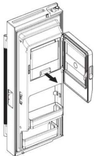
■ Remove the ice storage bin by inserting your fingers into a hole at the base of the bin and squeezing the latch to re the bin from the compartment. Lift the storage bin up and straight out.
natural_image
Technical line drawing of an open refrigerator with internal compartments and door opening (no text or symbols)
■ Replace the storage bin inside the ice compartment and push down to make sure it is firmly in place.
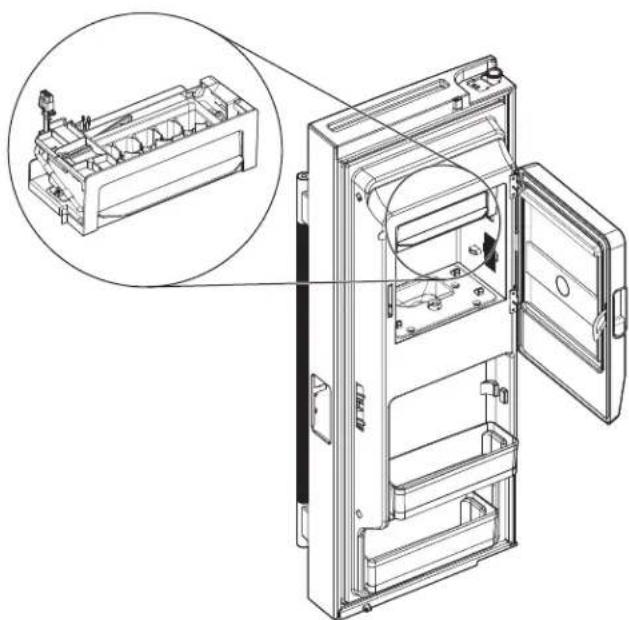
In-Door Ice Maker On/Off (Refrigerator Left Door)
The ice maker is located on the left door behind the bins. Ice cubes are ejected into the ice storage bin located on the left-hand refrigerator door.
■ You
natural_image
Technical line drawing of an open refrigerator internal compartments, showing internal structure and part assembly (no text or labels)
Freezer Ice Maker On/Off
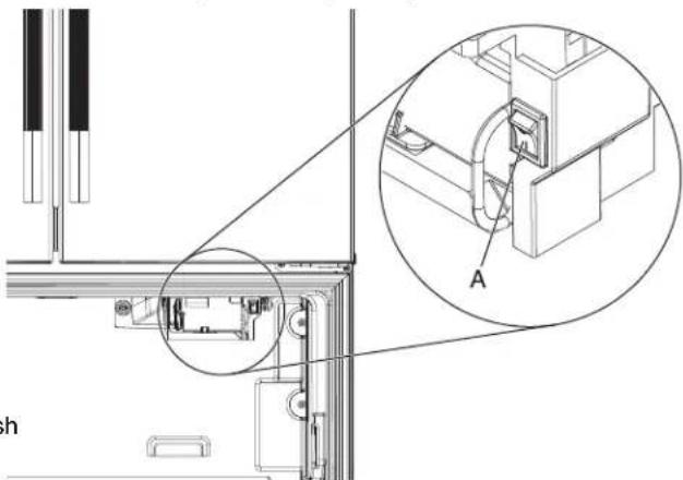
The Freezer ice maker is in the top right area of the Freezer easepartment.
PHI Freezer ice maker is ON by default when you receive the product.
To Turn the Freezer Ice Maker On/Off:
Locate the switch on the ice maker frame.
■ The 'I' icon (or switch position) indicates the ice maker is ON.
■ The 'o' icon (or switch position) indicates the ice maker is OFF
natural_image
Technical line drawing of a mechanical assembly with an inset showing a close-up view of a component labeled 'A' (no text or symbols present)
A. Freezer ice maker switch
NOTE:
■ You do not need to turn the Freezer ice maker OFF when the ice bin is full.
■ The ice maker has an automatic sensor that stops ice production when the ice bin is full.
If the Freezer ice maker is ON, it will make ice until the ice b is full. It will start to make ice again after you remove ice from the ice bin.
Water Filtration System
Do not use with water that is microbiologically unsafe or of unknown quality without adequate disinfection before or after the system. Systems certified for cyst reduction may be used on disinfected waters that may contain filterable cysts.
IMPORTANT: The disposable water filter should be replaced at least every 6 months. If the water flow to the water dispenser or ice maker decreases noticeably before 6 months have passed, replace the water filter more often.
Install the Water Filter
To order a replacement filter, contact us at www.whirlpool.com/owners. See the "Quick Start Guide" for details.
NOTE: If the filter is not installed correctly, water may dispense a lower flow rate and there will be slower ice production. Improve filter installation may also cause the water filter housing to leak.
The ice maker in the refrigerator's left door is ON by default when you receive the product.
To Turn the In-Door Ice Maker OFF:
■ Press and hold the Water dispense button and the Refrigerator button at the same time for 3 seconds. (applicable only for Whirlpool external water and ice dispenser models)
■ Press and hold the Cubed Ice button and the Crushed Ice button at the same time for 3 seconds. (applicable only for KitchenAid and JennAir models)
Left Hand Side of Refrigerator Ceiling
-
Locate the accessory packet in the refrigerator and remove the water filter.
-
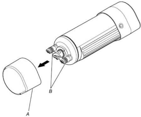
Take the water filter out of its packaging and remove the co from the O-rings. Be sure the O-rings are still in place after cover is removed.
-
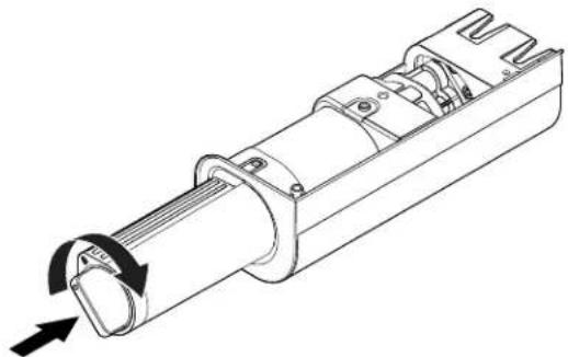
Turn the filter clockwise 90° (1/4 turn), until it locks into the housing.
NOTE: If the filter is not correctly locked into the housing, the
water dispenser will not operate. Water will not flow from the dispenser.
natural_image
Technical line drawing of a mechanical device with labeled parts A and B, showing internal components and an arrow indicating assembly (no text or symbols beyond labels)
A. O-ring cover
B. O-rings
-
The other cover with water drop icon that comes together the filter should be kept, that will be required later on the Water filter installation.
-
The water filter compartment is located in the left side of refrigerator ceiling.
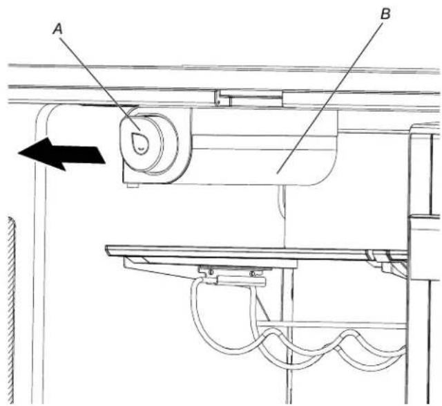
A. Water filter
B. Water filter housing
natural_image
Technical line drawing of a mechanical component with directional arrows indicating rotation (no text or symbols)
-
Add the filter housing cover from step 3 in the front of the water filter.
-
Flush the water system. See "Water and Ice Dispensers" for details.
IMPORTANT: If you do not flush the water system, you may experience dripping and/or decreased flow from the water dispenser.
Replacing the Water Filter
To purchase a replacement water filter, use model number EDRARXD1/EDRARXD1B, contact your dealer, or call
1-800-442-9991 in the U.S.A. or 1-800-807-6777 in Canada.
IMPORTANT: Air trapped in the water system may cause water and filter to eject. Always dispense water for at least 2 minutes before removing the filter or blue bypass cap.
-
Remove the water filter cover and save that for your replacement filter that will be installed later.
-
Turn filter counterclockwise, and pull straight out to remove.
NOTE: There may be some water in the filter. Some spilling may occur. Use a towel to wipe up any spills.
-
The water filter compartment is located in the left side of the refrigerator ceiling.
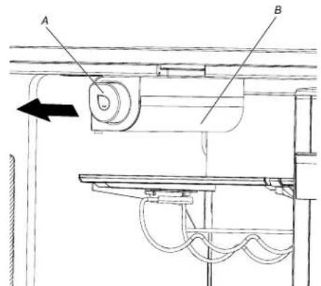
A. Water filter
B. Water filter housing
-
Align the water filter in the filter housing, insert filter until it touches the back of the housing.
-
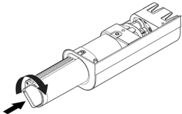
Turn the filter clockwise 90° (1/4 turn), until it locks into the housing.
NOTE: If the filter is not correctly locked into the housing, water dispenser will not operate. Water will not flow from a dispenser.
natural_image
Technical line drawing of a mechanical component with directional arrows indicating rotation (no text or symbols)
- Add the filter housing cover from step 3 in the front of the water filter.
- Flush the water system. See "Water and Ice Dispensers" for details.
IMPORTANT: If you do not flush the water system, you experience dripping and/or decreased flow from the water dispenser.
NOTE: The dispenser feature may be used without a water filter installed. Your water will not be filtered.
Reset Water Filter Status
After replacing the water filter, press and hold Reset Filter or Reset (depending on your model) for 3 seconds. See the "Quick Start Guide" for more information.
Style 1: Water filter reset on side door panel control
Displays the status of the water filter. To reset the water press Pantry and Control Lock for 3 seconds. See "Water Filtration System".
■ Order a replacement filter, icon blinks 3 times while dispensing water.
■ Replace the water filter, silicon blinks and alert tone will sound 3 times while dispensing water.
Touch Pantry and Control Lock at the same time on the temperature control display for 3 seconds to reset water filter.
Style 2: Water filter reset on the front door panel control
The Water Filter Status indicator displays the status of the water filter.
■ The “Replace Filter” icon will illuminate and blink continuously during dispensing when the rated volume of water has passed through the filter or 6 months have passed since the filter was installed.
A new water filter should be installed immediately when the "Replace Filter" light is illuminated.
■ After 14 days at Replace Filter stage, the "Replace Filter" and "water" icons will glow at all times and blink continuously during dispensing. Also, an alert chime will sound three times following dispensing. The water filter should be replaced at least every 6 months.
After changing the water filter, the user needs to reset the filter status light. Press and hold the "Freezer" and "Drawer" button for 3 seconds to reset the Water filter status. After that, the icon "Replace Filter" will turn OFF. (applicable only for Whirlpool external water and ice dispenser models)
After changing the water filter, the user needs to reset the filter status light. Press and hold the "Control Lock" and "Measure Fill" button for 3 seconds to reset the Water filter status. After that, the icon "Replace Filter" will turn OFF. (applicable only for KitchenAid and JennAir models)
DOOR AND HANDLE INSTRUCTIONS
Door and Drawers
Depending on the width of your doorway, you may need to remove the doors to move the refrigerator into your home. Also, the door hinges are factory installed on the right-hand side.
IMPORTANT:
If the refrigerator was previously installed and you are moving it out of the home, before you begin, turn the refrigerator or control Off, and unplug the refrigerator or disconnect power. Remove food and any adjustable door or utility bins from hay doors.
- Keep the refrigerator doors closed until you are ready to lift them free from the cabinet. Provide additional support for the refrigerator door while the hinges are being removed. Do not depend on the door gasket magnets to hold the door in place while you are working.
Tools Needed: 5/16", 3/8", and 1/4" hex head socket wrenches, FORX+ T25 screwdriver, #2 Phillips screwdriver, and a flat-blade
Remove and Replace Handles
rREFRIGERATOR DOOR HANDLES
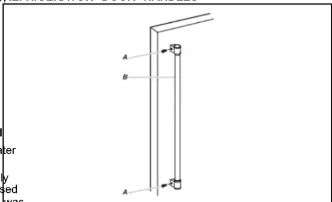
A. Flat-Head Handle Screws B. Refrigerator Door Handle
■ Using a 3/32" or 1/8" hex key, loosen the two setscrews located on the side of each handle. Pull the handle straight out from the drawer. Make sure you keep the screws for reattaching the handles.
To replace the handles, reverse the directions.
FREEZER DOOR HANDLES
Freezer Door Handle Style 1

■ Using a 3/32" or 1/8" hex key, loosen the two setscrews located on the side of each handle. Pull the handle straight from the drawer. Make sure you keep the screws for reattaching the handles.
■ To replace the handles, reverse the directions.
Freezer Door Handle Style 2
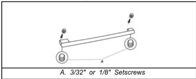
■ Using a 3/32" or 1/8" hex key, loosen the two setscrews located on the side of each handle. Pull the handle straight from the drawer. Make sure you keep the screws for reattaching the handles.
■ To replace the handles, reverse the directions.
Remove Refrigerator Doors and Hinges
Remove Right-Hand Refrigerator Door
- Unplug refrigerator or disconnect power.
- Starting with the right-hand side door, remove the top hinge cover using two hinge cover screws.
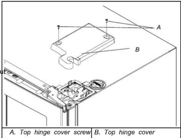
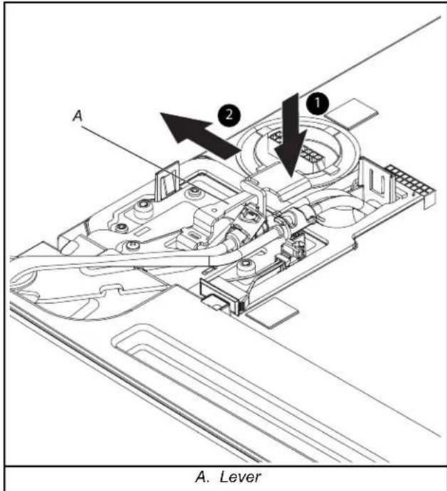
- Push the hinge lever and pull it as shown below. Remove and keep the hinge lever aside for replacing the doors later.
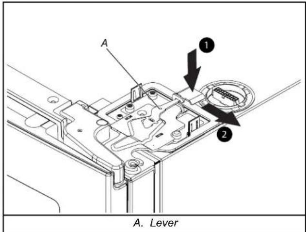
NOTE: Do not remove the two locator screws. These screws will help you align the hinge when you replace the door.
WARNING
Excessive Weight Hazard
Use two or more people to lift the appliance door.
Failure to do so can result in back or other injury.
- Lift the refrigerator door from the bottom hinge pin. The top hinge will come away with the door.
Remove Left-Hand Refrigerator Door
IMPORTANT: On models with a water dispenser, the tubing and wiring for the water dispenser run through the left-hand door hinge, so they must be disconnected before removing the door.
- Starting with the right-hand side door, remove the top hinge cover using two hinge cover screws.
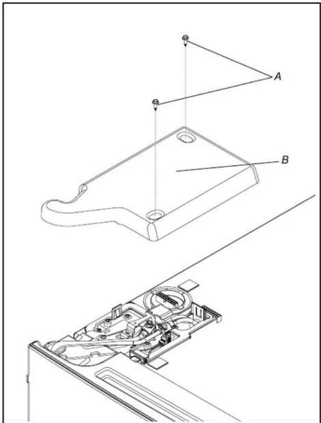
A. Top hinge cover screw B. Top hinge cover
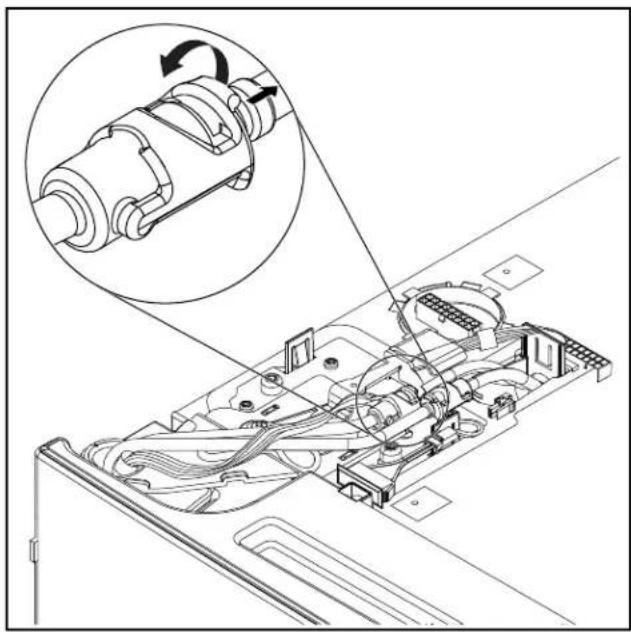
- Disconnect the water dispenser tubing located on top of the door hinge (if applicable).
Water Tubing Connection Style 1: Lift the clip holding the water lines to allow water line to be disconnected. The clip wi remain in one water line to allow reconnect the water line late
NOTE: The water dispenser tubing remains attached to the left-hand refrigerator door.
natural_image
Technical diagram of an electronic device showing internal components and a magnified inset of a mechanical assembly (no text or symbols)
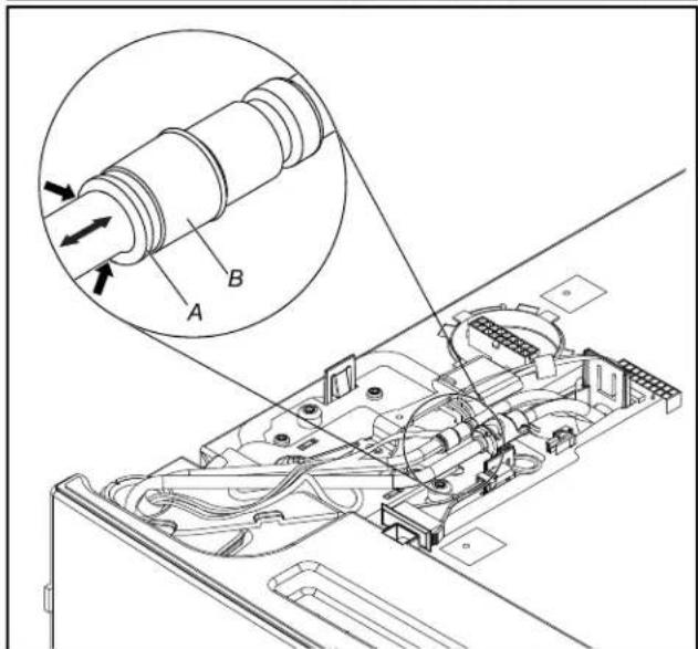
A. Outer ring B. Face of fitting
- Before removing the left-hand side door, disconnect the wirir plug located on top of the top hinge by pressing the latch allow the connectors to disengage and pull the connectors apart from each other.
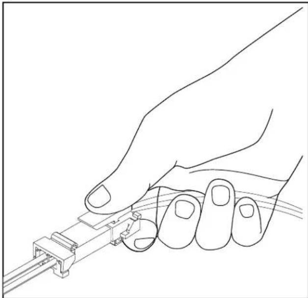
natural_image
Line drawing of a hand holding a small mechanical component (no text or symbols)
NOTE: Do not remove the green ground wire. It should attached to the door hinge.
- Push the hinge lever and pull it as shown below. Remove keep the hinge lever aside for replacing the doors later.
- Lift the refrigerator door from the bottom hinge pin. The top hinge will come away with the door.
NOTE: It may not be necessary to remove the bottom hinges and brake feet assemblies to move the refrigerator through a doorway.
■ Only if necessary, depending on your model, use a driver with a #2 square bit tip or a TORX T25 screwdriver to remove the bottom hinges and a 3/8" nut driver or a TORX T25 screwdriver to remove the brake feet screws.
Replace Refrigerator Doors and Hinges
Replace Right-Hand Refrigerator Door
- Set the right-hand door onto the bottom hinge pin.
- Insert the top hinge pin into the open hole in the top of the refrigerator door.
- Put the hinge lever into the hinge. Push the hinge lever until i is secure. Make sure the hinge lever is locked.
- Install the top hinge cover using two hinge cover screws.
Replace Left-Hand Refrigerator Door
IMPORTANT: Do not intertwine the water tubing and wiring bundles when reconnecting them.
- Set the left-hand door onto the bottom hinge pin.
- Insert the top hinge pin into the open hole in the top of the refrigerator door.
- Put the hinge lever into the hinge. Push the hinge lever until it is secure. Make sure the hinge lever is locked.
- Install the top hinge cover using two hinge cover screws.
- If applicable, reconnect the water dispenser tubing.
Style 1 - Insert the tubing firmly into the fitting until it stops. Close the clasp around the tubing. The clasp snaps into place between the fitting and the collar.
- Reconnect the electrical wiring.
■ Push together the two sections of the wiring plug.
remain Final Steps
-
Completely tighten the internal screws.
-
Replace both top hinge covers.
-
Completely tighten the internal screws.
- Replace both top hinge covers.
Remove and Replace Refrigerator Drawer
Depending on the width of your door opening, it may be necessary to remove the drawer fronts to move the refrigerator into your home.
REMOVE DRAWER FRONT
IMPORTANT:
If the refrigerator was previously installed and you are moving it out of the home, before you begin, turn the refrigerator control Off, and unplug the refrigerator or disconnect power. Remove food and any adjustable door or utility bins from doors.
■ Two people may be required to remove and replace the freezer drawer. Graphics are included later in this section.
Tools Needed: 1/4" Hex head nut driver, Flat-blade screwdriver
Style 1: Bottom Screws
- Loosen the two top screws attaching the drawer glide brackets to the drawer front.
NOTE: Loosen screws three to four turns. Keep the screws in the drawer front.
-
Remove the two bottom screws attaching the drawer glide.
-
Lift the drawer front up and off the top screws.
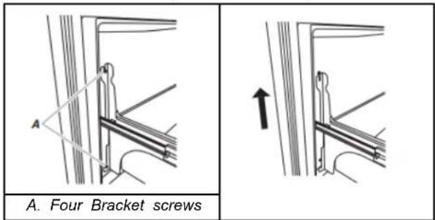
- Slide the drawer glides back into the refrigerator.
REPLACE DRAWER FRONT
-
Pull out the drawer glides until they are fully extended.
-
Style 1: Bottom Screws
■ Lower the loosened screws in the top of the door front into the upper notches in the drawer glide.
■ Align the holes in the bottom of the drawer glides.
■ Replace two screws removed previously and tighten all four screws.
NOTE: It helps if one person holds the drawer glides steady while another person aligns the drawer front and inserts the screws into the notches.
Remove and Replace Freezer Drawer Front
Depending on the width of your door opening, it may be necessary to remove the freezer drawer front to move the refrigerator into your home.
IMPORTANT:
If the refrigerator was previously installed and you are moving it out of the home, before you begin, turn the refrigerator control Off, and unplug the refrigerator or disconnect power. Remove food and any adjustable door or utility bins from doors.
■ Two people may be required to remove and replace the freezer drawer.
Tools Needed: 1/4" hex driver
REMOVE DRAWER
- Open the freezer drawer to full extension.
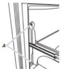
- Loosen the four screws attaching the drawer glides to the drawer front as shown below.
NOTE: Loosen screws three to four turns. Keep the screws drawer front.
natural_image
Technical line drawing of a mechanical bracket or bracket assembly with no visible text or symbols
A. Four Bracket screws
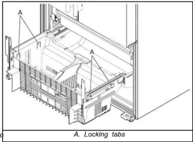
- Press the four locking tabs on the freezer drawer basket and lift the basket to unlock it.
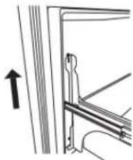
- Lift drawer front upward and off the screws.
natural_image
Pure mechanical assembly diagram showing bracket and mounting detail without any text or symbols
REPLACE DRAWER
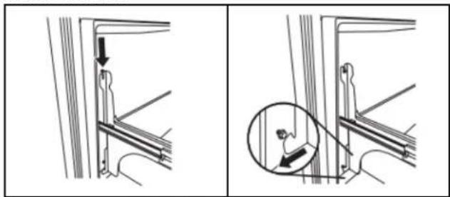
- Slide the drawer glides out of the freezer compartment.
- Insert the screws in the top of the drawer into the slots in the drawer brackets.
natural_image
Two-panel diagram showing structural connection details: one with a downward arrow and arrow, the other with a magnified inset of a person climbing stairs (no text or symbols)
- the Completely tighten all four screws.
Freezer Drawer Alignment
The freezer drawer can be adjusted for better sealing or alignment, please call for service.
Door Closing and Alignment
Make sure the refrigerator is steady. If the refrigerator seems unsteady or rolls forward when a door or drawer is pulled open, adjust the brake feet.
To Steady the Refrigerator:
■ Open the freezer drawer. Using a 1/4" hex driver, turn both brake feet clockwise the same amount until the brake feet are snug against the floor. Check again. If you are not satisfied, continue to adjust the brake feet by half turns of the screw un the refrigerator does not roll forward when the drawer is opened.
NOTE: Having someone push against the top of the refrigerator takes some weight off the leveling screws. This makes it easier to turn the screws.
NOTE: To allow the refrigerator to roll easier, raise the brake fee by turning them counterclockwise. The front rollers will be touching the floor.
- Move the refrigerator to its final location.
- Make sure the doors close easily. If you are satisfied with the door opening and closing, skip the next section and go to "Align the Doors." If, however, the doors do not close easily of the doors pop open, adjust the tilt.
- Using a 1/4" hex driver, lower the brake feet. Turn them clockwise until the rollers are off the floor and both brake feet are snug against the floor. This keeps the refrigerator from rolling forward when operating the refrigerator doors freezer drawer.
IMPORTANT: If you need to make further adjustments involving the brake feet, you must turn both brake feet the same amount to keep the refrigerator level.
- Use a level to make sure the refrigerator is level from side to side and front to back.
- Make sure the doors are even at the top and that the space between the bottom of the refrigerator doors and the top of the freezer drawer is even. If necessary, align the doors.
To Adjust the Cabinet Tilt:
- Open the freezer drawer. Use a 1/4" hex driver to turn both brake feet clockwise the same amount. This will raise the front of the refrigerator. It may take several turns to allow the doors to close easily.
NOTE: Having someone push against the top of the refrigerator takes some weight off the brake feet. This makes it easier to turn them.
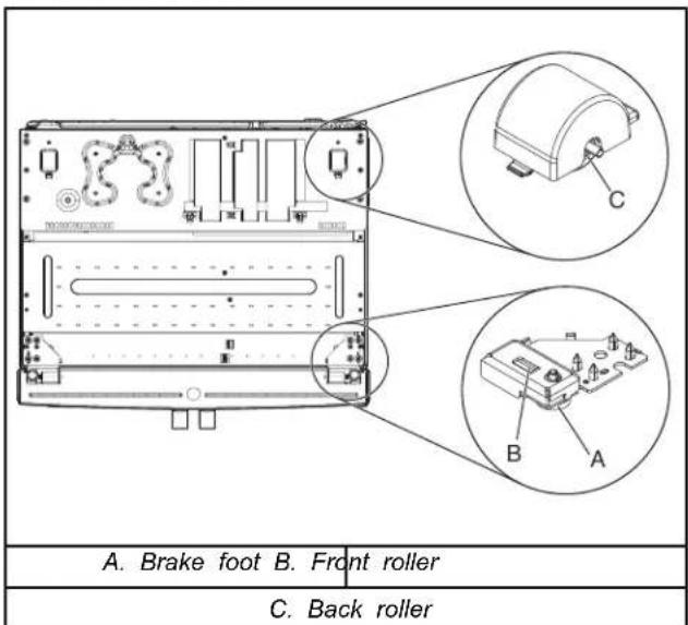
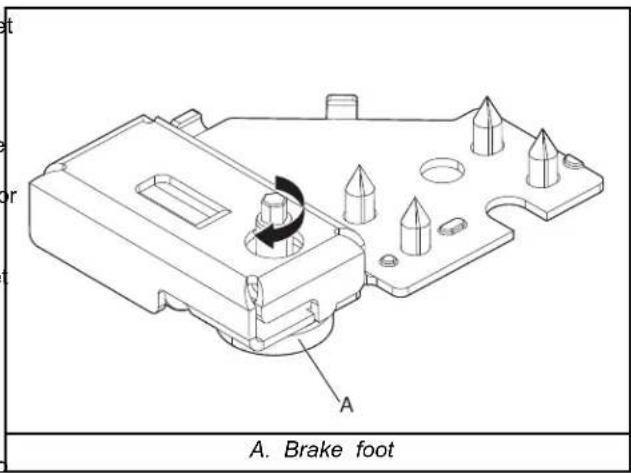
- Make sure the doors are even at the top and that the space face between the bottom of the refrigerator doors and the top of the door of the freezer drawer is even. If necessary, align the doors.
■ To Align the Doors:
- Keeping both refrigerator doors closed, pull out the freezer drawer. Locate the bottom hinge pin of the right-hand refrigerator door. The alignment screw is inside the bottom hinge pin.
- Insert the short end of the 1/8" hex key (packed with the Door Handle Installation Instructions) into the bottom hinge pin until it is fully engaged in the alignment screw.
To raise the refrigerator door, turn the hex key to the right. To lower the door, turn the hex key to the left.
■ Continue to turn the alignment screw until the doors are aligned.
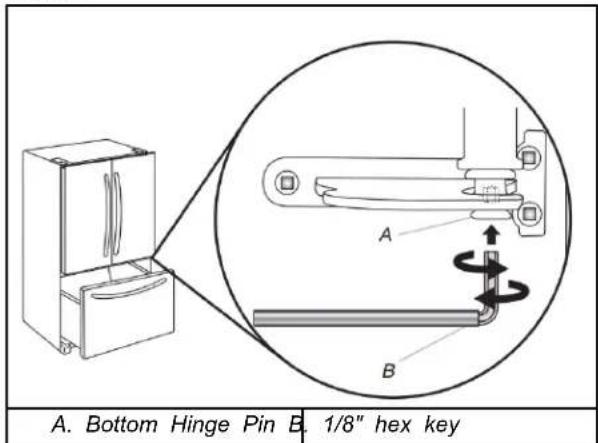
After making all appropriate adjustments, replace the base grille by aligning the ends of the grille with the leveling assemblies on each side and snapping the grille into place. Use a 1/4" hex drive to reinstall screws if applicable.
Final Steps
WARNING
Electrical Shock Hazard
Plug into a grounded 3 prong outlet.
Do not remove ground prong.
Do not use an adapter.
Do not use an extension cord.
Failure to follow these instructions can result in death, fire, or electrical shock.
- Plug into a grounded 3 prong outlet.
- Reset the controls. See "Control Panel Descriptions" in the Quick Start Guide for details.
- Return all removable door parts to doors and the food to refrigerator.
TROUBLESHOOTING
Refrigerator Operation
First try the solutions suggested here to avoid service call. If need further assistance, refer to the contact information in the "Quick Start Guide."
The Refrigerator will not Operate
WARNING
Electrical Shock Hazard
Plug into a grounded 3 prong outlet.
Do not remove ground prong.
Do not use an adapter.
Do not use an extension cord.
Failure to follow these instructions can result in death, fire, or electrical shock.
■ Power cord unplugged? Plug into a grounded 3 prong outlet.
■ Is outlet working? Plug in a lamp to see if the outlet is working.
■ Household fuse blown or circuit breaker tripped? Replace the fuse or reset the circuit breaker. If the problem continues, call an electrician.
■ Are controls on? Make sure the refrigerator controls are on. See "Using the Controls."
■ Is refrigerator defrosting? Your refrigerator will regularly run an automatic defrost cycle. Recheck in 45 minutes to see if it is operating.
■ New installation? Allow 24 hours following installation for the refrigerator to cool completely.
NOTE: Adjusting the temperature controls to the coldest setting will not cool either compartment more quickly.
The Motor Seems to Run too Much
Your new refrigerator may run longer than your old one due to its high-efficiency compressor and fans. The unit may run even longer if the room is warm, a large food load is added, doors are opened often, or if the doors have been left open.
If the Refrigerator is Noisy
Refrigerator noise has been reduced over the years. Due to this reduction, you may hear intermittent noises from your new refrigerator that you did not notice from your old model. Below are listed some normal sounds with an explanation.
■ Buzzing - heard when the water valve opens to fill the ice maker.
■ Pulsating - fans/compressor adjusting to optimize performance.
■ Rattling - flow of refrigerant, water line, or from items placed on top of the refrigerator.
■ Sizzling/Gurgling - water dripping on the heater during defrost cycle.
■ Popping - contraction/expansion of inside walls, especially during initial cool-down.
■ Water running - may be heard when water melts during the defrost cycle and runs into the drain pan.
■ Creaking/Cracking - occurs as ice is being ejected from the ice maker mold.
■ Banging noise during ice maker or water dispensing you operation - Check if a water hammer arrestor is required to be installed. Refer to the "Water Supply Requirements" section for more information.
There is no Audible Door Open Alarm
Has the door been open less than 10 minutes?
The door open alarm will only flash when the door has been open for 10 minutes. The audible alarm will sound the first time the door is left open for more than 10 minutes. Subsequent door open alarms will only flash. You must reset the audible alarm each time. See "Using the Controls."
The Doors will not Close Completely
■ Door blocked open? Move food packages away from door.
■ Bin or shelf in the way? Push bin or shelf back in the corre position.
WARNING
Explosion Hazard
Keep flammable materials and vapors, such as gas away from appliance.
Use nonflammable cleaner.
Failure to do so can result in death, explosion, or
■ Large amount of ice recently removed? Allow 24 hours for ice maker to produce more ice.
■ Ice cube jammed in the ice maker ejector arm? Remove ice from the ejector arm with a plastic utensil.
■ Reverse osmosis water filtration system connected to your cold water supply? This can decrease water pressure. See "Water Supply Requirements".
The Ice Cubes are Hollow or Small
NOTE: This is an indication of low water pressure.
■ Water shut-off valve not fully open? Turn the water shut-off valve fully open.
■ Kink in the water source line? A kink in the line can reduce water flow. Straighten the water source line.
■ Reverse osmosis water filtration system connected to your cold water supply? This can decrease water pressure. See "Water Supply Requirements."
■ Questions remain regarding water pressure? Call a pap licensed, qualified plumber.
Are the gaskets dirty or sticky? Clean gaskets with mild and warm water.
The Lights Do not Work
Is the refrigerator in Sabbath mode? See "Using the Controls
Has the door been open more than 10 minutes? See "Using the Controls."
Temperature and Moisture
Temperature is Too Warm
■ New installation? Allow 24 hours following installation for refrigerator to cool completely.
■ Door(s) opened often or left open? Allows warm air to refrigerator. Minimize door openings and keep doors fully closed.
■ Large load of food added? Allow several hours for refrigerator to return to normal temperature.
■ Controls set correctly for the surrounding conditions? Adjust the controls a setting colder. Check temperature in 24 hours. See “Using the Controls.”
■ Refrigerator not cooling? For models with digital controls, turn the refrigerator off and then on to reset. If this does correct the problem, call for service.
■ Air vents blocked? Remove any item from in front of the vents.
There is Interior Moisture Buildup
NOTE: Some moisture buildup is normal.
■ Humid room? Contributes to moisture buildup.
■ Door(s) opened often or left open? Allows humid air to refrigerator. Minimize door openings and keep doors fully closed.
Ice and Water
The Ice Maker is Not Producing Ice or not E Ice
■ Refrigerator connected to a water supply and the supply shut-off valve turned on? Connect refrigerator to water supply and turn water shut-off valve fully open.
■ Kink in the water source line? A kink in the line can reduce water flow. Straighten the water source line.
■ Ice maker turned on? Make sure switch is in the ON position.
■ New installation? Wait 24 hours after ice maker installation for ice production to begin. Wait around 72 hours for full ice production.
Ice is Sticking Together in the Ice Storage Bin
■ It is normal for frost to be on top of the ice storage bin due to colds."normal opening and closing of the freezer.
It is normal for ice to stick together when it is not dispensed caused frequently. It is recommended that the ice storage bin be emptied and cleaned as needed. See "Ice Maker and Storage Bin."
Off-Taste, Odor or Gray Color in the Ice
■ New plumbing connections? New plumbing connections can be cause discolored or off-flavored ice.
■ Ice stored too long? Discard ice. Wash ice bin. Allowente24 hours for ice maker to make new ice.
■ Odor transfer from food? Use airtight, moisture proof packaging to store food.
■ Are there minerals (such as sulfur) in the water? A water filter may need to be installed to remove the minerals.
■ Is there a water filter installed on the refrigerator? Gray or dark discoloration in ice indicates that the water filtration system needs additional flushing.
The Ice Dispenser Will Not Operate Properly
■ Freezer door closed completely? Close the door firmly. If it does not close completely, see "The doors will not close completely."
■ Ice bin installed correctly? Be sure the ice bin is firmly in position.
■ New installation? Wait 24 hours after ice maker installation for ice production to begin. Wait around 72 hours for full ice production.
■ Ice stuck in the delivery chute? Remove the Ice Bin from the door. Use a plastic utensil to clear the delivery chute.
■ Has the wrong ice been added to the bin? Use only cubes produced by the current ice maker.
■ Has the ice melted around the auger (metal spiral) in the ought bin? Empty the ice container. Use warm water to melt the ice if necessary.
WARNING
Cut Hazard
Use a sturdy glass when dispensing ice.
Failure to do so can result in cuts.
Water is Leaking from the Dispenser
NOTE: One or two drops of water after dispensing is normal.
■ Glass not being held under the dispenser long enough? Hold the glass under the dispenser 2 to 3 seconds after releasing the dispenser lever.
■ New installation? Flush the water system. See “Prepare the Water System” or “Water and Ice Dispensers.”
■ Recently changed water filter? Flush the water system. See "Prepare the Water System" or "Water and Ice Dispensers."
The Dispenser Water is not Cool Enough
NOTE: Water from the dispenser is chilled to only 50^ F ( 10^ C).
■ New installation? Allow 24 hours after installation for the water supply to cool completely.
■ Recently dispensed large amount of water? Allow 24 hours for water supply to cool completely.
■ Is the ice dispenser stalling while dispensing "crushed" ■ Water not been recently dispensed? The first glass of water ice? Change the ice button from "crushed" to "cubed." If cubed may not be cool. Discard the first glass of water.
ice dispenses correctly, depress the button for "crushed" ice ■ Refrigerator connected to a cold water pipe? Make sure the refrigerator is connected to a cold water pipe. See "Water and begin dispensing again.
■ Has the dispenser arm been held in too long? Ice will stop Supply Requirements. dispensing when the arm is held in too long. Wait 3 minutes for dispenser motor to reset before using again.
The Water Dispenser will not Operate Properly
■ Freezer door closed completely? Close the door firmly. If it does not close completely, see "The doors will not close completely."
■ Refrigerator connected to a water supply and the supply shut-off valve turned on? Connect refrigerator to water supply and turn water shut-off valve fully open.
■ Is the water pressure at least 30 psi (207 kPa)? The water pressure to the home determines the flow from the dispenser. See “Water Supply Requirements.”
■ Kink in the home water source line? Straighten the water source line.
■ New installation? Flush and fill the water system.
■ Water filter installed on the refrigerator? The filter may be clogged or incorrectly installed.
■ Is a reverse osmosis water filtration system connected to your cold water supply? See "Water Supply Requirements" in either the Installation Instructions or the Use & Care Guide.
Water Filtration System
Model W11569863 (PID), W11569861 (Without PID)
Replacement element model numbers: EDRARXD1/EDRARXD1B/W11536439/WHRARXD1/WHRARXD1B/KADARXD1/KADARXD1B/MAYARXD1/MAYARXD1B/W11486187
Capacity 200 Gallons (757 Liters) with PID W11569863, 100 Gallons (379 Liters) without PID W11569861.

System tested and certified by NSF International against CSA B483.1, NSF/ANSI Standards 42, 53, and 401 for the reduction of the claims specified on the Performance Data Sheet below.
This system has been tested according to NSF/ANSI Standards 42, 53, 401, and CSA B483.1 for the reduction of the substances listed below. The concentration of the indicated substances in water entering the system was reduced to a concentration less than or equal to the permissible limit for water leaving the system, as specified in NSF/ANSI Standards 42, 53, 401, and CSA B483.1.
Test Parameters: pH = 7.5 ± 0.5 unless otherwise noted. Flow = 0.52 GPM (1.97 LPM). Pressure = 60 psi (413.7 kPa). Temperature = 68°F to 71.6°F (20°C to 22°C). Rated service capacity = 200 gallons (757 liters) W11569863 with PID, 100 gallons (379 liters) W11569861 without PID.
| Substance Reduction Aesthetic Effects | Influent Challenge Concentration | Reduction Requirements | Average % Reduction | Minimum % Reduction |
| Chlorine Taste/Odor 2.0 | mg/L ± 10% ≥ 50% reduction 99.39 99 | | | |
| Particulate Class I* At | least 10,000 particles/mL | ≥ 85% reduction 99.52 | 99.33 | |
| Microplastics At least 1 | 0,000 particles/mL | ≥ 85% reduction 99.52 | 99.33 | |
| Contaminant Reduction | Influent Challenge Concentration | Reduction Requirements | Average % Reduction | Minimum % Reduction |
| Lead: @ pH 6.5 / @ 8.5 | pBL150 mg/L ± 10% 0.005 mg/L 99.29/99.84 | | 99.07/99.46 | |
| Mercury: @ pH 6.5 / @ pH 8.5 | 0.006 mg/L ± 10% 0.002 mg/L 97.38/92.78 | | 92.98/75.86 | |
| Asbestos | 107 to 10 fibers/L†† | ≥ 99% | > 99.0 | > 99.0 |
| Cystst | 50,000/L minimum | ≥ 99.95% | ≥ 99.997 | > 99.997 |
| Atrazine | 0.009 mg/L ± 10% 0.003 mg/L > 98.98 | | > 98.95 | |
| Benzene | 0.015 mg/L ± 10% 0.005 mg/L > 99.28 | | > 99.17 | |
| Carbofuran 0.080 mg/L | ± 10% 0.040 mg/L 83.93 58.7 | | | |
| Lindane | 0.002 mg/L ± 10% 0.0002 mg/L 95.22 95 | | | |
| P-Dichlorobenzene | 0.225 mg/L ± 10% 0.075 mg/L 99.95 99.95 | | | |
| Tetrachloroethylene | 0.015 mg/L ± 10% 0.005 mg/L 99.33 99.29 | | | |
| Toxaphene | 0.015 mg/L ± 10% 0.003 mg/L 99.27 99.17 | | | |
| O-Dichlorobenzene | 1.8 mg/L± 10% | 0.6 mg/L | > 99.995 | > 99.995 |
| Toluene | 3.0 mg/L ± 10% | 1.0 mg/L | > 99.9 | > 99.9 |
| Styrene | 2.0 mg/L ± 10% | 0.1 mg/L | > 99.9 | > 99.9 |
| 1,2,4-Trichlorobenzene | 0.210 mg/L ± 10% | 0.07 mg/L | > 99.55 | > 99.42 |
| Trichloroethylene | 0.3 mg/L ± 30% 0.005 | mg/L > 99.8 | > 99.8 | |
| Endrin | 0.006 mg/L ± 10% 0.002 mg/L 92.32 83.93 | | | |
| Ethylbenzene | 2.1 mg/L ± 10% | 0.7 mg/L | > 99.99 | > 99.99 |
| 2,4 - D 0.210 mg/L ± | 10% 0.07 mg/L 98.89 94.76 | | | |
| Turbidity 11 NTU ± 10 | % 0.5 NTU 98.88 98.17 | | | |
| Atenolol 200 ± 20% 30 | ng/L 95.27 94.98 | | | |
| Carbamazepine 1400 ± | 20% 200 ng/L | 96.2 | 96.09 | |
| Linuron | 140 ± 20% 20 ng/L 93.53 92.31 | | | |
| Meprobamate | 400 ± 20% 60 ng/L 94.54 94.32 | | | |
| Trimethoprim | 140 ± 20% 20 ng/L 96.27 95.94 | | | |
| DEET | 1400 ± 20% 200 ng/L | 96.32 96.21 | | |
| Metolachlor | 1400 ± 20% 200 ng/L | 96.67 96.5 | | |
| Bisphenol A | 2000 ± 20% 300 ng/L | 95.07 94.82 | | |
| Estrone | 140 ± 20% 20 ng/L 96.27 96.15 | | | |
| Nonylphenol | 1400 ± 20% 200 ng/L | 92.61 90.48 | | |
| Naproxen | 140 ± 20% 20 ng/L 96.09 95.83 | | | |
| Ibuprofen | 400 ± 20% 60 ng/L 95.44 95.13 | | | |
| TCPP | 5000 ± 20% 700 ng/L | 92.78 92.59 | | |
| TCEP | 5000 ± 20% 700 ng/L | 96.62 96.55 | | |
| Phenytoin | 200 ± 20% 30 ng/L 95.6 | 95.12 | | |
| VOC** 0.300 mg/L ± 10 | % 0.015 mg/L | > 99.58 | > 96.21 | |
The compounds certified under NSF 401 have been deemed as “emerging compounds/incidental contaminants.” Emerging compounds/incidental contaminants compounds that have been detected in drinking water supplies at trace levels. While occurring at only trace levels, these compounds can affect the public acceptance/perception of drinking water quality.
It is essential that operational, maintenance, and filter replacement requirements be carried out for the product to perform as advertised. Property damage can occur if all instructions are not followed.
■ The disposable cartridge must be changed at least every 6 months. Spent adsorption media will not be regenerated used.
■ Use replacement EDRARXD1/B, WHRARXD1/B, KADARXD1/B, MAYARXD1/. 2025 suggested retail price of \59.99 U.S.A./\69.99 Canada. Prices are subject to change without notice. Available at www.everydropwater.com.
■ The filter monitor system measures the amount of water that passes through the filter and alerts you when it is time to be the filter. To learn how to check the water filter status, see the Controls" or "Water Filtration System" in the User Instruction or User Guide.
■ After changing the water filter, flush the water system. See "Water and Ice Dispensers" or "Water Dispenser" in the User Instructions or User Guide.
These contaminants are not necessarily in your water supply. While testing was performed under standard laboratory conditions, actual performance may vary.
■ The product is for cold water use only.
■ The water system must be installed in compliance with state local laws and regulations.
■ Actual performance may vary as the testing was performed under standard laboratory conditions.
■ Do not use with water that is microbiologically unsafe or of unknown quality without adequate disinfection before or after the system. Systems certified for cyst reduction may be used on disinfected waters that may contain filterable cysts. EPA Est. No. 85075-SG-001.
■Refer to the "Warranty" section (in the User Instructions or User Guide) for the Manufacturer's limited warranty, name and telephone number.
Application Guidelines/Water Supply Parameters
Water Supply Potable City or Well
| Water,Replace | 30 psi-120 psi |
| “Using | (207 kPa-827 kPa) |
Waters Temperature 33°F-100°F (0.6°C-37.8°C)
| Service Flow Rate | 0.52 GPM (1.97 LPM) |
| @ 60 psi (413.7 kPa) |
■ Your water filtration system will withstand up to 120 psi water pressure. If your water supply is higher than 80 psi, install a pressure reducing valve before installing the water filtration system.
■ Conforms to NSF/ANSI 53 for VOC reduction. See Table below for individual contaminants and reduction performance.
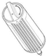
**This VOC performance accounts for 39 contaminant removals based on VOC surrogate testing
^ Based on the use of polystyrene microsphere
^++ Fibers greater than 10 um in length
Performance data sheet reduction claims for organic chemicals included by surrogate testing
| Substance Influent challenge concentration (mg/L) Maximum permissible product water concentration (mg/L) |
| alachlor 0.050 0.001 | | |
| altrazine 0.100 0.003 | | |
| benzene 0.081 0.001 | | |
| carbofuran 0.190 0.001 | | |
| carbon tetrachloride 0.078 0.0018 | | |
| chlorobenzene 0.077 0.001 | | |
| chloropicrin 0.015 0.0002 | | |
| 2,4-d 0.110 0.0017 | | |
| dibromochloropropane (DBCP) 0.052 0.00002 | | |
| o-dichlorobenzene 0.080 0.001 | | |
| p-dichlorobenzene 0.040 0.001 | | |
| 1,2-dichloroethane | 0.088 0.0048 | |
| 1,1-dichloroethylene | 0.083 0.001 | |
| cis-1,2-dichloroethylene | 0.170 0.0005 | |
| trans-1,2-dichloroethylene | 0.086 0.001 | |
| 1,2-dichloropropane | 0.080 0.001 | |
| cis- 1,3-dichloropropylene | 0.079 0.001 | |
| dinoseb 0.170 0.002 | | |
| endrin | 0.053 0.00059 | |
| ethylbenzene | 0.088 0.001 | |
| ethylene dibromide (EDB) | 0.044 0.00002 | |
| haloacetonitriles (HAN) | | |
| bromochloroacetonitrile | 0.022 0.0005 | |
| dibromoacetonitrile | 0.024 0.0006 | |
| dichloroacetonitrile | 0.0096 | 0.0002 |
| trichloraacetonitrile | 0.015 0.0003 | |
| haloketones (HK) | | |
| 1,1-dichloro-2-propanone | 0.0072 | 0.0001 |
| 1,1,1-trichloro-2-propanone | 0.0082 | 0.0003 |
| heptachor | 0.025 0.00001 | |
| heptachor epoxide 0.0107 | 0.0002 | |
| hexachlorobutadiene | 0.044 0.001 | |
| hexachlorocyclopentadiene | 0.060 0.000002 | |
| lindane | 0.055 0.00001 | |
| methoxychlor | 0.050 0.0001 | |
| pentachlorophenol 0.096 0.001 | | |
| simazine | 0.120 0.004 | |
| styrene | 0.150 0.0005 | |
| 1,1,2,2-tetrachloroethane 0.081 0.001 | | |
| tetrachloroethylene 0.081 0.001 | | |
| toluene 0.078 0.001 | | |
| 2,4,5-TP (Silvex) 0.270 0.0016 | | |
| tribromoacetic acid 0.042 0.001 | | |
| 1,2,4-trichlorobenzene 0.160 0.0005 | | |
| 1,1,1-trichloroethane 0.084 0.0046 | | |
| 1,1,2-trichloroethane 0.150 0.0005 | | |
| trichloroethylene 0.180 0.0010 | | |
| trihalomethanes (includes) chloroform (surrogate chemical) bromoform 0.300 0.015 bromodichloromethane chlorodibromomethane | | |
| xylenes (total) 0.070 0.001 | | |
Consumer Support 1-800-442-9991
By Whirlpool Corporation
2000 North M63
Benton Harbor, MI 49022
SÉCURITÉ DU RÉFRIGÉRATEUR
natural_image
Technical line drawing of a mechanical device with internal shelves and doors (no text or symbols)
Nettoyage
AVERTISSEMENT
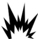
Risque d'explosion
natural_image
Isometric line drawing of a rectangular frame with triangular supports at the base (no text or symbols)
natural_image
Technical line drawing of a mechanical frame assembly with mounting bracket and directional arrow (no text or symbols)
natural_image
Technical line drawing of a mechanical component with an arrow indicating downward motion (no text or symbols)
Refermer la tablette :
natural_image
Technical line drawing of a mechanical assembly with mounting brackets and a central frame (no text or symbols)
natural_image
Technical line drawing of a mechanical frame assembly with mounting brackets (no text or symbols)
natural_image
Diagram of a mechanical assembly with a rectangular plate and vertical supports, no text or symbols present
natural_image
Technical line drawing of a multi-panel refrigerator with an arrow indicating upward motion (no text or symbols)
natural_image
Technical line drawings of two 3D architectural or mechanical components with internal structural details (no text or symbols)
natural_image
Isometric line drawing of a multi-story building interior with structural framework and a black arrow indicating direction (no text or symbols)
natural_image
Technical line drawing of a mechanical device with internal components and a downward arrow indicating motion (no text or symbols)
A. Séparateur
natural_image
Technical line drawing of a multi-level mechanical assembly with internal components and a black arrow indicating a specific part (no text or symbols present)
natural_image
Technical line drawing of a mechanical assembly with no visible text or symbols
natural_image
Technical line drawing of a cabinet or enclosure with internal shelves and handle (no text or symbols)
natural_image
Line drawing of a cabinet or enclosure with a triangular roof and door, no text or symbols present
A. Couvre-charnière
natural_image
Isometric line drawing of a rectangular box with internal door and labeled dimensions A, B, C (no text or symbols beyond labels)
| UGS | Largeur (A) | Hauteur (B) | Profondeur (C) |
| KRFC236S*;WRFC3036R*;WRFC5036R*;WRFC5236R*;WRMC5036R*;WRMC7036R*;WRFC7036R*;KRFC636S*;KRFC536S* | 36 po(914,6 mm) | 70^3/16 po(1 782,4 mm) | 30^1/2 po(774 mm) |
| KRFC336S*;JFFCCI72S*;KRFC936S*;KRFC736S*;JFFCCE72S* | 72^1/8 po(1832,4 mm) |
■ Ensure that you have the proper length needed for the job. Be sure both ends of the copper tubing are cut square.
natural_image
Line drawing of a rectangular electronic device with ventilation slots and a lid (no text or symbols)
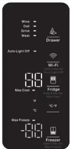
Activation/désactivation des notifications sonores
natural_image
Technical line drawing of an open refrigerator with door and drawer (no text or symbols)
natural_image
Technical line drawing of an open refrigerator with internal components and a magnified inset showing internal structure (no text or symbols)

natural_image
Technical line drawing of a mechanical device with labeled parts A and B, showing assembly or assembly steps (no text or symbols beyond labels)
natural_image
Technical line drawing of a mechanical component with directional arrows indicating rotation (no text or symbols)
A. Filtre à eau
natural_image
Technical line drawing of a mechanical component with directional arrows indicating rotation (no text or symbols)
natural_image
Simple diagram of a curved beam with two fixed supports at one end and one at the other, labeled A (no text or symbols)
natural_image
Simple line drawing of a lever with two weights and a fulcrum, labeled A (no text or symbols)
natural_image
Technical line drawing of a mechanical assembly with an inset showing a rotating component (no text or symbols present)
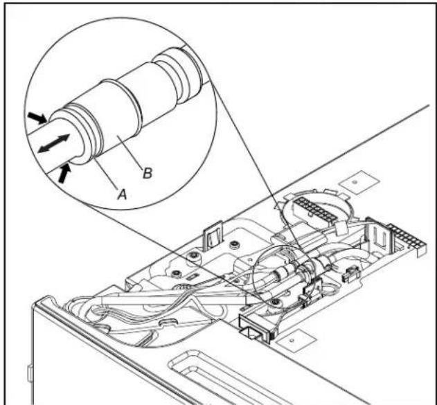
A. Bague externe B. Avant du raccord
natural_image
Line drawing of a hand holding a small electronic component (no text or symbols)
natural_image
Diagram of a door handle assembly with an arrow indicating direction (no text or symbols)
RÉINSTALLER LE TIROIR
natural_image
Technical diagram showing two mechanical assembly steps: one with a downward arrow and arrow, the other with a magnified inset of a person's arm (no text or symbols)
natural_image
Technical line drawing of a mechanical component with multiple conical features and a labeled section A (no text or symbols beyond label)