
LP55280 - Buffet hygiene protection Vollrath - Free user manual and instructions
Find the device manual for free LP55280 Vollrath in PDF.

| Product Type | Buffet hygiene protection (articulated glass sneeze guard with profile) |
| Model | LP55280 |
| Brand | Vollrath |
| Category | Buffet hygiene protection |
| Configuration | 5 compartments (5-Comp./Pan) |
| Main Material | Glass and stainless steel |
| Estimated Length | Approximately 223.5 cm (88 in) for the corresponding heating strip |
| Power Supply | Heating strip and/or lighting, requires connection by a qualified electrician |
| Main Functions | Articulated sneeze guard, hygienic protection of buffet food, possibility of adding heating strip and lighting |
| Installation | On stainless steel countertop or other materials, with drilling template provided |
| Maintenance | Cleaning of glass with a soft cloth and glass cleaner, disassembly possible for maintenance |
| Safety | Installation and electrical connection reserved for a qualified electrician; do not overtighten the caps |
| Available Spare Parts | Heating strip kits (ref. 350744-350751) and lighting kit, gaskets, caps, etc. (see manual) |
| Repairability | Removal and replacement of glass possible, ballast bar included for stability |
| Customer Service | Vollrath: 800.628.0830 (US); techservicereps@vollrathco.com |
Frequently Asked Questions - LP55280 Vollrath
User questions about LP55280 Vollrath
0 question about this device. Answer the ones you know or ask your own.
Ask a new question about this device
Download the instructions for your Buffet hygiene protection in PDF format for free! Find your manual LP55280 - Vollrath and take your electronic device back in hand. On this page are published all the documents necessary for the use of your device. LP55280 by Vollrath.
USER MANUAL LP55280 Vollrath
Low Profile Hinged Glass Breath Guards
| Item No. | Style Length | ||
| For Signature Server®With Stainless Steel Countertops | For Drop-ins and Signature Server®With Non-Stainless Steel Countertops | ||
| — LP55277 | Double-Sided Buffet | 2-Well/Pan | |
| 55278 LP55278 | 3-Well/Pan | ||
| 55279 LP55279 | 4-Well/Pan | ||
| 55280 LP55280 | 5-Well/Pan | ||
| 55281 LP55281 | 6-Well/Pan | ||
| — LP55319 | Single-Sided Buffet with Top Shelf | 2-Well/Pan | |
| 55315 LP55315 | 3-Well/Pan | ||
| 55316 LP55316 | 4-Well/Pan | ||
| 55317 LP55317 | 5-Well/Pan | ||
| 55318 LP55318 | 6-Well/Pan | ||
TABLE OF CONTENTS
Breath Guard Installation ......page 1
Single-Sided RetroFit Kit Installation ......page 5
Heat Strip Installation ......page 7
Light Strip Installation ......page 8
natural_image
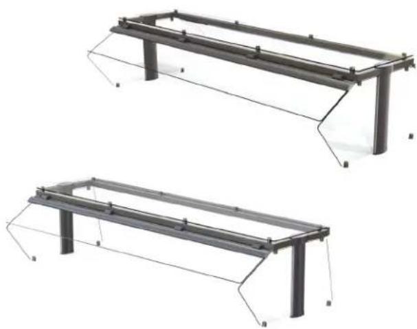
Two identical metal frame structures with support beams and mounting feet, shown from different angles (no text or symbols)BREATH GUARD INSTALLATION
Before You Begin
-
Download the specification sheet from Vollrath.com. You will need to refer to this document for dimensions and NSF requirements.
-
Know the countertop manufacturer's requirements for preparing and installing equipment into the countertop prior to starting installation.
Tools You Will Need
- Drilling template, included
- 9/32" drill bit
• Allen wrench, included
- ^13/_32 " drill bit
- Hammer
- 1" drill bit
- Drill
- 7/16^ combo wrench
- Spotting punch
- 9/16 " combo wrench
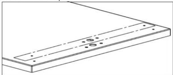
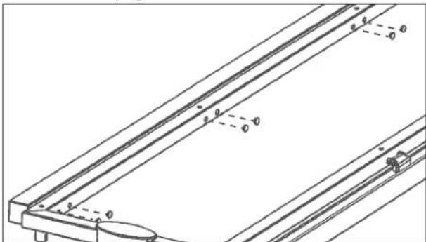
Drill Mounting Holes
NOTICE: Countertop materials require specific preparation. Refer to the countertop manufacturer for instructions regarding the proper installation of equipment into the material.
- Place the cut out template over one end of the countertop. Follow the instructions on the template.
natural_image
Technical line drawing of a rectangular panel with mounting holes and dashed lines indicating hidden edges (no text or symbols)- Repeat step 1 on the other end of the countertop.
Assemble and Mount the Breath Guard
- Assemble the tie rods.
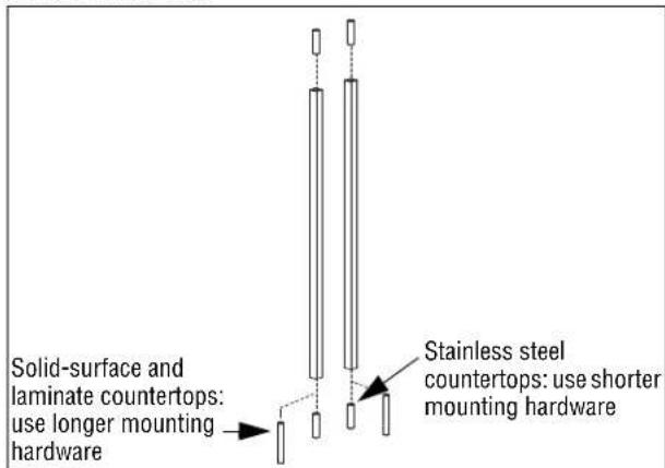
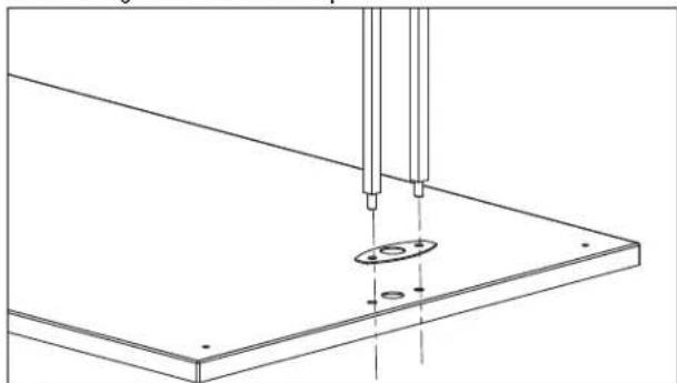
- Set the mounting gasket in place. Insert the tie rods through the holes in the gasket and countertop.
natural_image
Technical line drawing of a mechanical assembly with two vertical rods inserted into a flat plate (no text or symbols)Please register your product at Vollrath.com/ProductRegister
BREATH GUARD INSTALLATION (CONTINUED)
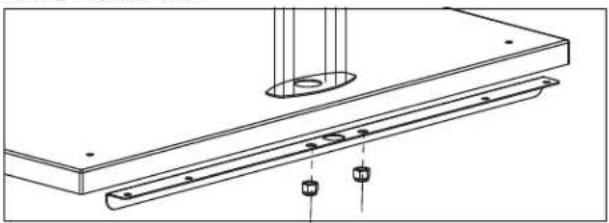
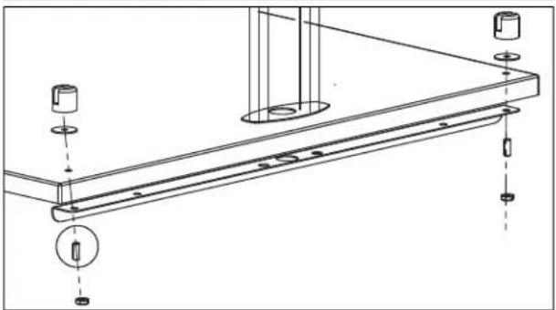
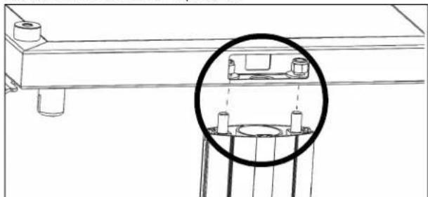
- Position the stiffening bracket on the underside of the countertop and over the tie rod extensions. Secure the tie rods to the base frame with the included nuts.
natural_image
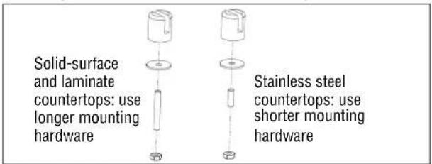
Technical line drawing of a mechanical assembly with mounting flange and support components (no text or symbols)- Install the gaskets and standoffs to the countertop.
natural_image
Technical line drawing of a mechanical assembly with mounting holes and a bracket (no text or symbols)- Position the stud so it is flush with the bottom of the slot in the standoff.
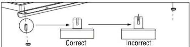
flowchart
graph LR
    A["Start"] --> B{Correct}
    B --> C{Incorrect}
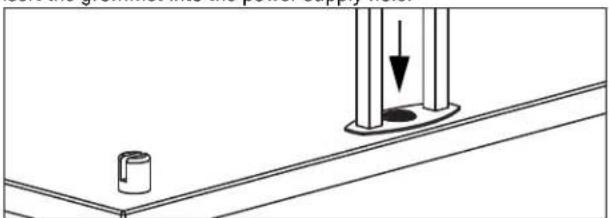
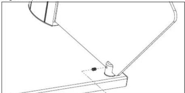
- Insert the grommet into the power supply hole.
natural_image
Technical line drawing of a mechanical assembly with a cylindrical component and a vertical rod (no text or symbols)- Slide the uprights over the tie rods:
- Smooth side facing inward and the grooved side facing outward - Spacer support tab must be at the bottom
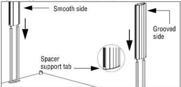
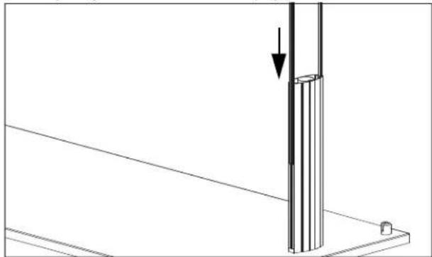
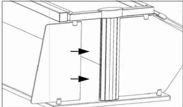
- Slide the glass gaskets into slots of the uprights.
natural_image
Technical line drawing of a vertical structural component with an arrow indicating force or direction (no text or symbols)If Your Breath Guard: Includes a heat strip and/or lights
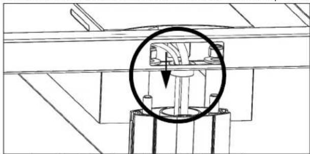
- Thread the wires through the upright and into the cabinet below. Use the included washers and nuts to attach the tie rods to the top frame.
natural_image
Technical line drawing of a mechanical assembly with a circled component (no text or symbols)-
If your breath includes a heat strip and/or lights, continue on page 7 with step 6.
-
If your breath guard contains only lights, continue below with step 13.
Does not include heat strips or lights
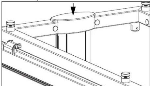
- Place the top frame over the uprights and thread the tie rods through the holes in the frame. Use the included washers and nuts to attach the tie rods to the top frame.
natural_image
Technical line drawing of a mechanical assembly with a magnified inset showing internal components (no text or symbols)- Install the end caps.
natural_image
Technical line drawing of a mechanical assembly with no visible text or symbolsBREATH GUARD INSTALLATION (CONTINUED)
Install the Glass Panels Long Side Panel(s)
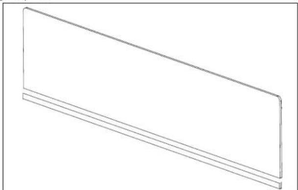
- Attach the gaskets to the square-cornered-side of the long-side glass panels.
natural_image
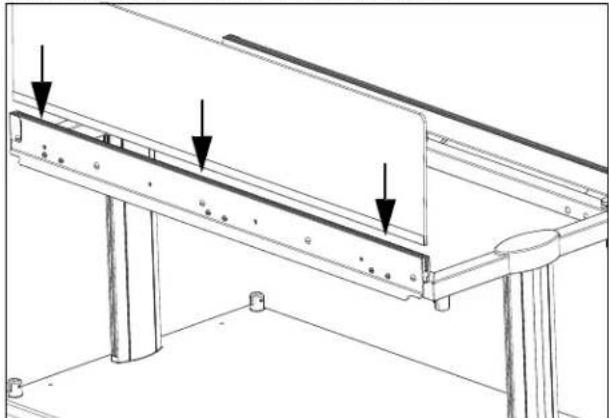
Simple line drawing of a rectangular panel or shelf with two horizontal lines, no text or symbols present.- Insert the gasket side of one long-side glass panel,
natural_image
Technical line drawing of a structural support frame with three downward-pointing arrows indicating force or detail (no text or symbols present)- Tighten the set screws to secure the glass in place.
natural_image
Technical line drawing of a mechanical bracket assembly with mounting feet and bolts (no text or symbols)- Repeat the steps for with long-side glass panel for the other side.
Short Side Panels
For Double Sided Breath Guards
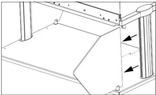
- Insert one short-end glass panel into the gasket on the upright support.
natural_image
Technical line drawing of a mechanical assembly with two arrows indicating directional components (no text or symbols present)- Tighten the sets screws on the top and bottom stand-offs.
natural_image
Technical line drawing of a mechanical assembly with a bracket and pivot point (no text or symbols)- Repeat the steps for the other short-end panel.
For Single Sided Breath Guards
- Insert the wider end glass panel into the gasket on the upright support below the long side glass panel. Insert the narrow panel on the other side.
natural_image
Technical line drawing of a mechanical assembly with directional arrows indicating movement or force (no text or symbols)- Tighten the sets screws on the top and bottom stand-offs to secure the glass in place.
natural_image
Technical line drawing of a mechanical assembly with a bracket and pin (no text or symbols)- Repeat for the other end.
BREATH GUARD INSTALLATION (CONTINUED)
Install the Glass Panels (Continued)
Top Panel
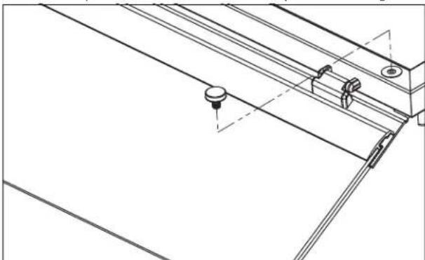
- Remove the caps from the stand-offs on the top of the breath guard.
natural_image
Technical line drawing of a mechanical assembly with mounting brackets and a central knob (no text or symbols)-
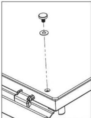
Set the top glass into place. Align the holes in the glass with the holes on the standoffs.
-
Thread the vinyl washers onto the caps and insert into the holes. Tighten the caps. Do not over tighten.
natural_image
Technical line drawing of a mechanical assembly with a hanging component and mounting bracket (no text or symbols)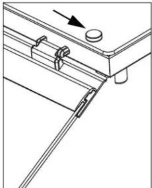
natural_image
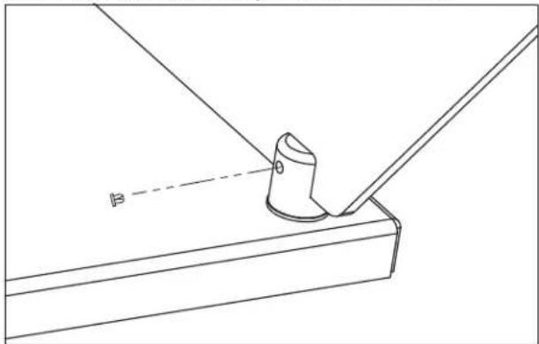
Technical line drawing of a mechanical assembly with no visible text or symbols- Adjust the set screws on both ends of the hinged glass panel to create a parallel gap between the hinged panel and the end glass.
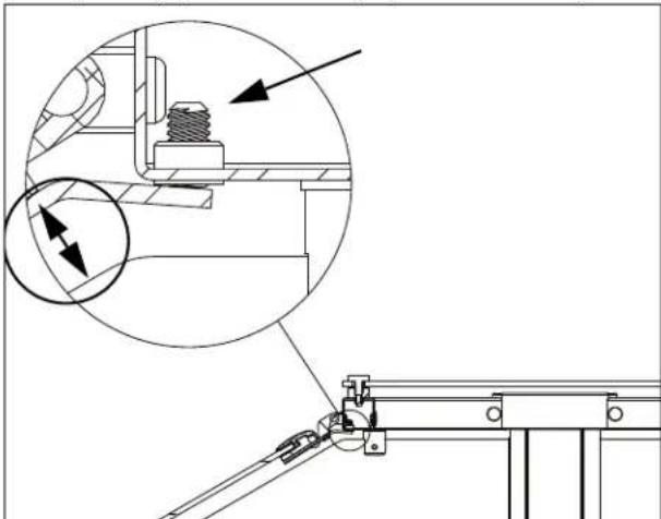
natural_image
Technical line drawing of a mechanical assembly with an inset showing a close-up of a bolt and a magnified detail (no text or symbols)Install the Cover Plugs
- Insert a cover plug over each set screw in the glass mounting bracket and stand-offs.
NOTICE: Set screw covers plugs must be inserted to meet NSF certification.
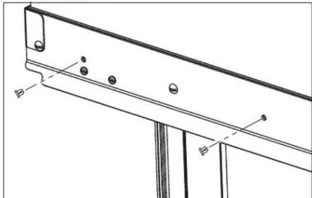
natural_image
Technical line drawing of a structural beam with mounting holes and support brackets (no text or symbols)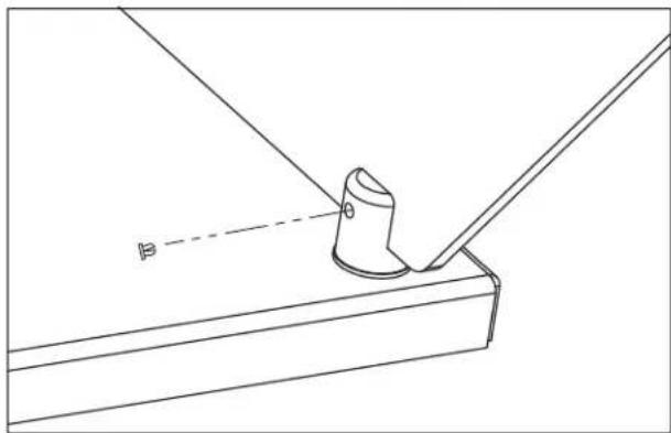
natural_image
Technical line drawing of a mechanical component with a cylindrical part inserted into a bracket (no text or symbols)SINGLE-SIDED RETROFIT KIT INSTALLATION
| Kit Item No. | Description | Kit Contents and Quantity | |||
| Ballast Bar | Narrow End Glass Panels | Mounting Bolts | Allen Wrenches | ||
| 350736 46" | 1 | 2 | 6 | 2 | |
| 350737 60" 6 | |||||
| 350738 74" 8 | |||||
| 350739 88" 8 | |||||
| 350740 2-Well 4 | |||||
| 350741 3-Well 6 | |||||
| 350742 4-Well 6 | |||||
| 350743 5-Well 8 | |||||
| 350744 6-Well 8 | |||||
Tools You Will Need
- 1/8" Allen wrench (supplied with breath guard)
- 5/32'' Allen Wrench (supplied with breath guard)
- Standard Screwdriver
Remove the Top Glass
- Loosen and remove the stand-offs.
natural_image
Technical line drawing of a mechanical assembly with no visible text or symbols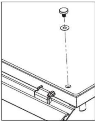
natural_image
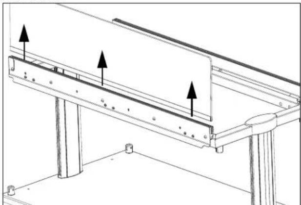
Technical line drawing of a mechanical assembly with a hanging component and mounting bracket (no text or symbols)- Lift off the top glass.
Remove the End Panels
- Loosen the sets screws on the top and bottom stand-offs.
natural_image
Technical line drawing of a mechanical component with a cylindrical part inserted into a bracket (no text or symbols)- Remove the glass.

natural_image
Technical line drawing of a mechanical assembly with no visible text or symbolsRemove the Long Side Glass Panel
- Remove the cover plugs over the set screws in the glass mounting bracket..
natural_image
Technical line drawing of a structural bracket with mounting holes and base plate (no text or symbols)- Loosen the set screws.
natural_image
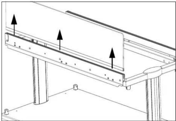
Technical line drawing of a mechanical bracket assembly with mounting holes and structural supports (no text or symbols)- Remove the glass.
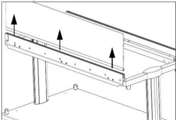
natural_image
Technical line drawing of a structural support frame with three upward-pointing arrows indicating assembly or force directions (no text or symbols present)SINGLE-SIDED RETROFIT KIT INSTALLATION (CONTINUED)
Remove the Mounting Bracket
- Remove the inner frame plugs. Save the plugs.
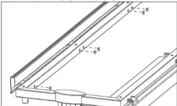
natural_image
Technical line drawing of a mechanical bracket assembly (no text or symbols)- Remove the hinge by removing the hinge assembly screws.
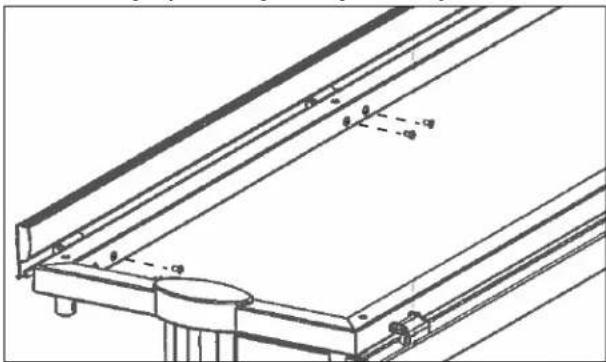
natural_image
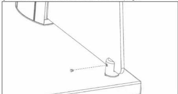
Technical line drawing of a structural frame with supports and mounting points (no text or symbols)Install the Ballast Bar
- Attach the ballast bar using the included screws.
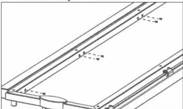
natural_image
Technical line drawing of a mechanical assembly with no visible text or symbols- Reinstall the frame plugs.
natural_image
Technical line drawing of a mechanical assembly with no visible text or symbolsInstall the End Glass
- Insert the included short-end glass panel into the gasket on the upright support.
natural_image
Technical line drawing of a mechanical assembly with two arrows indicating directional flow or force (no text or symbols present)- Tighten the set screws and install the set screw plugs.
natural_image
Technical line drawing of a mechanical assembly with a bracket and pivot point (no text or symbols)- Repeat for the other end.
Reinstall the Top Glass
- Set the top glass into place. Align the holes on the glass with the holes on the stand-offs. Thread the vinyl washers onto the caps and insert into the holes. Tighten the caps. Do not over tighten.

natural_image
Technical line drawing of a mechanical assembly with a suspended component and mounting bracket (no text or symbols)
natural_image
Technical line drawing of a mechanical assembly with no visible text or symbolsEnd Profile of Single Sided Breath Guard
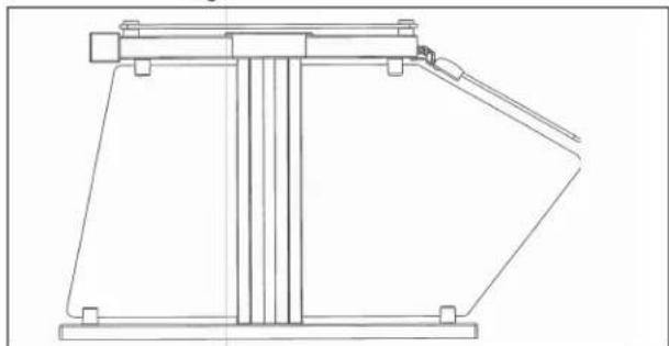
natural_image
Technical line drawing of a mechanical lifting device (no text or symbols)HEAT STRIP INSTALLATION
| Kit Item No. | For Use Over |
| 350752 46' | |
| 350753 60' | |
| 350754 74' | |
| 350755 88' | |
| 350756 2 Well | |
| 350757 3 Well | |
| 350758 4 Well | |
| 350759 5 Well | |
| 350755 6 Well |
NOTICE: Heat strip connections must be performed by a licensed electrician.
NOTICE: Installation requires two people to lift the heat strip into place.
If this is a retrofit installation
Remove the upright caps and top glass before proceeding with the installation.
Installation
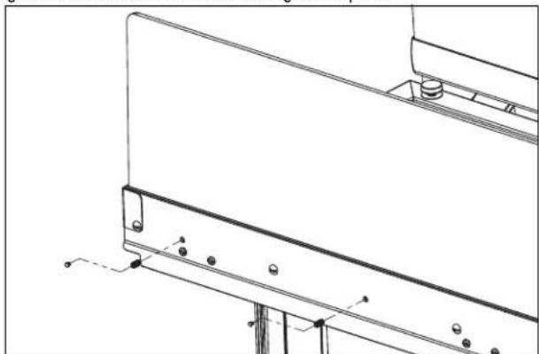
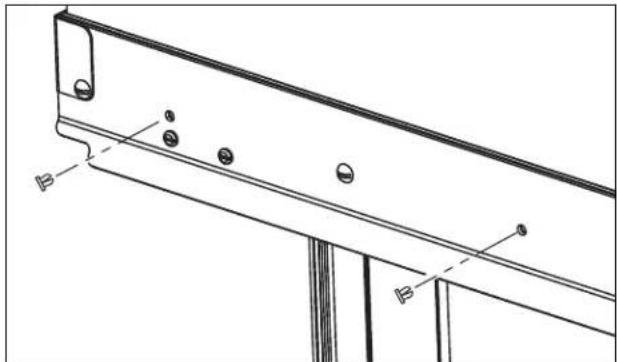
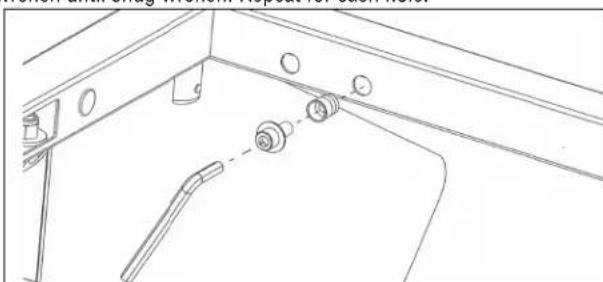
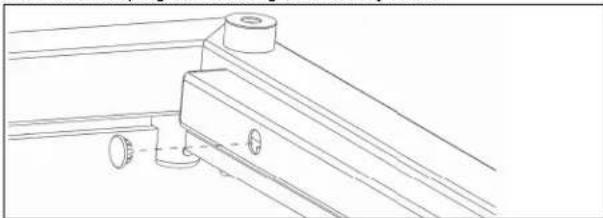
- Press the threaded inserts into frame holes next to the access hole. Install a bolt with a washer into an anchor. Tighten with the supplied allen wrench. Repeat for each hole.
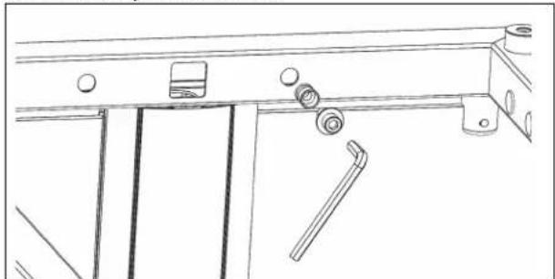
natural_image
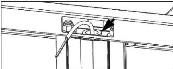
Technical line drawing of a mechanical assembly with rollers and fixtures (no text or symbols)- Install the included large grommet into the frame hole on the power supply end. Pull the power supply wiring from the cabinet up through the hole in the upright.
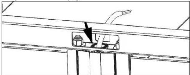
natural_image
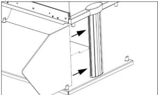
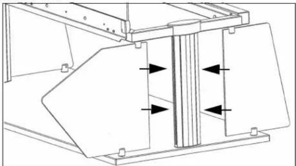
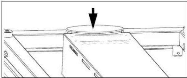
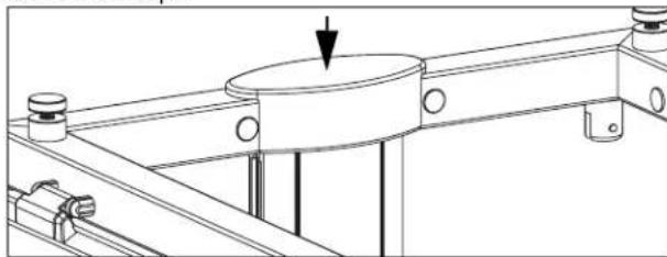
Technical line drawing of a mechanical assembly with a component highlighted by an arrow (no text or symbols present)- With two people, lift up the heat strip assembly through the middle of frame until the shroud is flush with the top of frame.
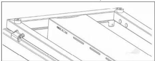
natural_image
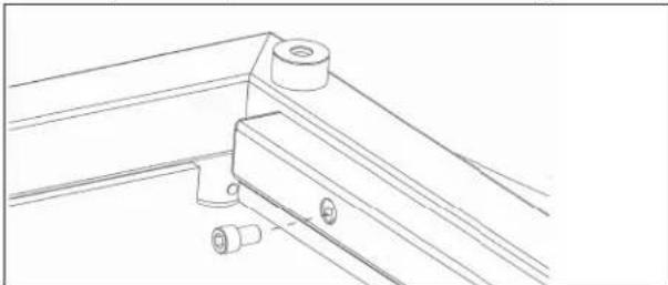
Technical line drawing of a mechanical frame structure with mounting holes and a central component (no text or symbols)- Mount the heat strip by installing and tightening the four included hex bolts and washers through the ends of the shroud and into the threaded inserts. (Shown looking up at the underside of the heat strip.)
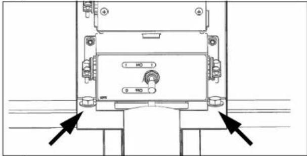
-
Wire the heat strip control box.
-
Attach the included rubber cord boot around the wire. The rounded side must face the top of the breath guard. Install the slotted end cap onto the frame and push the boot firmly into the slot. (Shown looking up at the underside of the heat strip.)
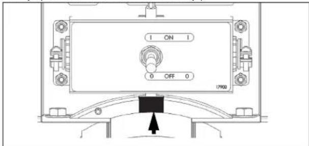
- Tighten the set screw until snug. (Shown looking up at the underside of the heat strip.)
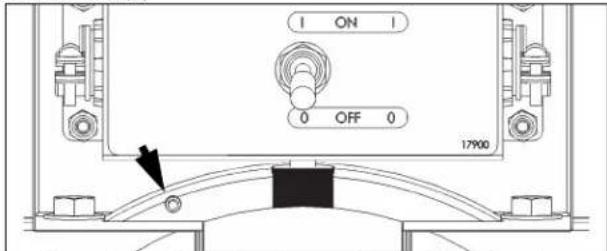
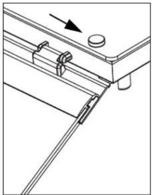
- Install the end cap without the slot onto the opposite end of the frame.
natural_image
Line drawing of a cabinet or rack with a circular top and arrow indicating direction (no text or symbols)LIGHT STRIP INSTALLATION
| Kit Item No. | For Use With | Kit Item No. | For Use With |
| 350744 46' 350748 | 2 Well | ||
| 350745 60' 350749 | 3 Well | ||
| 350746 74' 350750 | 4 Well | ||
| 350747 88' 350751 | 5 Well | ||
| 350747 6 Well | |||
NOTICE: Light assembly connection must be performed by a licensed electrician.
If this is a retrofit installation
- Remove the upright caps and top glass before proceeding with the installation.
- Remove the frame plugs from the insides of the long sides of the top frame.
Installation
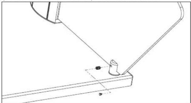
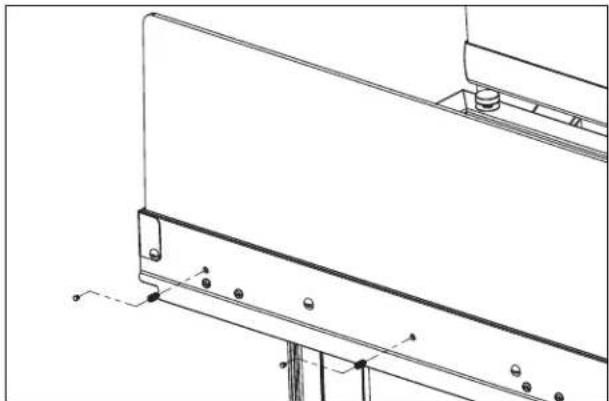
- Center and hold the light assembly up to the inside of the front or back frame tube. Mark holes that will require mounting anchor.
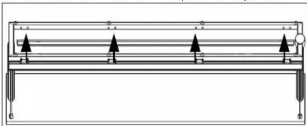
natural_image
Pure technical diagram of a mechanical or electrical assembly with no text, numbers, or symbols- Press the threaded inserts into the marked frame holes. Install a bolt with washer into an anchor and tighten with the supplied allen wrench until snug wrench. Repeat for each hole.
natural_image
Technical line drawing of a mechanical assembly with no visible text or symbols- Install the included large grommet into the frame hole on the power supply end. Pull the power supply wiring from the cabinet up through the hole in the upright.
natural_image
Technical line drawing of a mechanical assembly with a tool and component (no text or symbols)- Install the included small grommet into the end frame hole nearest to the power supply. Pull the power supply wiring through the frame and through the grommet installed in the end hole.
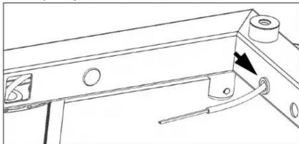
natural_image
Technical line drawing of a mechanical bracket with mounting holes and a tool, showing no text or symbols- Wire the light. Tuck the wire nuts into the back of the light assembly.
- Attach the light assembly to the frame tube with the supplied bolts.
natural_image
Technical line drawing of a mechanical bracket assembly (no text or symbols)- Install the hole plugs into the light assembly holes.
natural_image
Technical line drawing of a mechanical bracket assembly (no text or symbols)- Install the end caps.
natural_image
Technical line drawing of a mechanical assembly with a central circular component and mounting flanges (no text or symbols)
Outperform every day."
www.vollrath.com
The Vollrath Company, L.L.C.
1236 North 18th Street
Sheboygan, WI 53081-3201 U.S.A.
Main Tel: 800.624.2051 or 920.457.4851
Main Fax: 800.752.5620 or 920.459.6573
Customer Service: 800.628.0830
Canada Customer Service: 800.695.8560
Technical Services
techservicereps@vollrathco.com
Induction Products: 800.825.6036
Countertop Warming Products: 800.354.1970
Toasters: 1-800-309-2250
All Other Products: 800.628.0832
natural_image
Two technical line drawings of a metal frame structure with support legs and structural supports (no text or symbols)INSTALLATION DU PARE-HALEINE
Avant de commencer
natural_image
Technical line drawing of a rectangular panel with mounting holes and dashed lines indicating hidden edges (no text or symbols)natural_image
Technical line drawing of a mechanical assembly with a base plate and two vertical rods inserted into it (no text or symbols)natural_image
Technical line drawing of a mechanical assembly with mounting base and support structure (no text or symbols)natural_image
Technical line drawing of a mechanical support structure with mounting holes and dashed alignment lines (no text or symbols)natural_image
Technical line drawing of a mechanical assembly with a cylindrical component and a curved component (no text or symbols)natural_image
Technical line drawing of a vertical support structure with an arrow indicating force or direction (no text or symbols)natural_image
Technical line drawing of a mechanical assembly with a magnified circular detail (no text or symbols)natural_image
Technical line drawing of a mechanical assembly with a magnified inset showing internal components (no text or symbols)natural_image
Technical line drawing of a mechanical assembly with no visible text or symbolsINSTALLATION DU PARE-HALEINE (SUITE)
natural_image
Simple line drawing of a rectangular panel or shelf with two horizontal lines, no text or symbols present.natural_image
Technical line drawing of a structural frame with three downward-pointing arrows indicating force or component (no text or symbols present)natural_image
Technical line drawing of a mechanical bracket assembly with mounting holes and structural supports (no text or symbols)natural_image
Technical line drawing of a mechanical assembly with two arrows indicating directional components (no text or symbols present)natural_image
Technical line drawing of a mechanical assembly with a pin and base plate (no text or symbols)natural_image
Technical line drawing of a mechanical assembly with directional arrows indicating movement or force (no text or symbols)natural_image
Technical line drawing of a mechanical assembly with a bracket and base plate (no text or symbols)natural_image
Technical line drawing of a mechanical assembly with mounting brackets and a central knob (no text or symbols)natural_image
Technical line drawing of a mechanical assembly with a hanging component and mounting bracket (no text or symbols)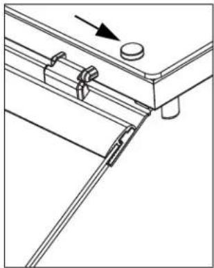
natural_image
Technical line drawing of a mechanical assembly with no visible text or symbolsnatural_image
Technical line drawing of a mechanical assembly with an inset showing a bolt and gear mechanism (no text or symbols)natural_image
Technical line drawing of a structural beam with mounting holes and support brackets (no text or symbols)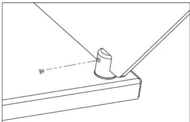
natural_image
Technical line drawing of a mechanical assembly with a cylindrical component and angled base (no text or symbols)INSTALLATION DU KIT DE RATTRAPAGE UN CÔTÉ
| N0d'articledu kit | Description | Contenu et quantité par kit | |||
| Barre de ballast | Panneaux de verre de côté | Boulons de montage | Clés Allen | ||
| 350736 4 | 6" (116, 8 cm) | 1 | 2 | 6 | 2 |
| 350737 6 | 0" (152, 4 cm) 6 | ||||
| 350738 7 | 4" (188 cm) 8 | ||||
| 350739 8 | 8" (223,5 cm) 8 | ||||
| 350740 2 | compartiments 4 | ||||
| 350741 3 | compartiments 6 | ||||
| 350742 4 | compartiments 6 | ||||
| 350743 5 | compartiments 8 | ||||
| 350744 6 | compartiments 8 | ||||
Matériel nécessaire
natural_image
Technical line drawing of a mechanical bracket assembly with no visible text or symbols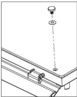
natural_image
Technical line drawing of a mechanical assembly with a hanging component and mounting bracket (no text or symbols)natural_image
Technical line drawing of a mechanical assembly with a pin and base plate (no text or symbols)- Enlevez la vitre.
natural_image
Technical line drawing of a mechanical assembly with no visible text or symbolsnatural_image
Technical line drawing of a structural beam with mounting holes and supports (no text or symbols)- Desserrez les vis.

natural_image
Technical line drawing of a mechanical bracket assembly with mounting holes and structural supports (no text or symbols)- Enlevez la vitre.
natural_image
Technical line drawing of a structural support frame with three upward-pointing arrows indicating assembly or force directions (no text or symbols present)INSTALLATION DU KIT DE RATTRAPAGE UN CÔTÉ (SUITE)
Dépose du support
natural_image
Technical line drawing of a mechanical frame assembly with no visible text or symbolsnatural_image
Technical line drawing of a structural frame with supports and mounting points (no text or symbols)natural_image
Technical line drawing of a mechanical assembly with no visible text or symbolsnatural_image
Technical line drawing of a mechanical bracket assembly with mounting holes and dashed alignment lines (no text or symbols)natural_image
Technical line drawing of a mechanical component with two arrows indicating direction (no text or symbols)natural_image
Technical line drawing of a mechanical assembly with a base and support structure (no text or symbols)natural_image
Technical line drawing of a mechanical assembly with a suspended component and mounting bracket (no text or symbols)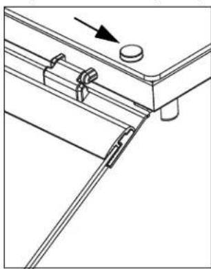
natural_image
Technical line drawing of a mechanical assembly with no visible text or symbolsnatural_image
Technical line drawing of a mechanical device with vertical supports and a handle (no text or symbols)INSTALLATION DE LA RAMPE CHAUFFANTE
| N° d'article du kit | Pour une utilisation sur |
| 350752 | 46" (116, 8 cm) |
| 350753 | 60" (152, 4 cm) |
| 350754 | 74" (188 cm) |
| 350755 | 88" (223,5 cm) |
| 350756 2 compartiments | |
| 350757 3 compartiments | |
| 350758 4 compartiments | |
| 350759 5 compartiments | |
| 350755 6 compartiments | |
natural_image
Technical line drawing of a mechanical assembly with rollers and fixtures (no text or symbols)natural_image
Technical line drawing of a mechanical assembly with a valve and base component (no text or symbols)natural_image
Technical line drawing of a metal frame structure with mounting holes and structural ribs (no text or symbols)natural_image
Line drawing of a cabinet or rack with a circular top and arrow indicating direction (no text or symbols)INSTALLATION DE LA RAMPE D'ÉCLAIRAGE
natural_image
Pure technical diagram of a mechanical or electrical component with no text, numbers, or symbolsnatural_image
Technical line drawing of a mechanical assembly with no visible text or symbolsnatural_image
Technical line drawing of a mechanical assembly with a tool and pipe (no text or symbols)natural_image
Technical line drawing of a mechanical component with a curved tool and directional arrow (no text or symbols)natural_image
Technical line drawing of a mechanical bracket assembly (no text or symbols)natural_image
Technical line drawing of a mechanical bracket assembly with no visible text or symbolsnatural_image
Technical line drawing of a mechanical assembly with a central circular component and mounting flanges (no text or symbols)
Outperform every day."
www.vollrath.com
The Vollrath Company, L.L.C.
1236 North 18th Street
natural_image
Two identical metal frame structures with support legs and structural supports, shown from different angles (no text or symbols)natural_image
Technical line drawing of a rectangular plate with internal features and mounting holes (no text or symbols)natural_image
Technical line drawing of a mechanical assembly with two vertical rods and a circular feature on a base plate (no text or symbols)natural_image
Technical line drawing of a mechanical assembly with mounting flange and support rails (no text or symbols)natural_image
Technical line drawing of a mechanical support structure with mounting holes and dashed alignment lines (no text or symbols)natural_image
Technical line drawing of a mechanical assembly with a cylindrical component and a downward arrow indicating force or motion (no text or symbols)natural_image
Technical line drawing of a mechanical assembly with a vertical rod and mounting base (no text or symbols)natural_image
Technical line drawing of a mechanical assembly with a magnified circular detail (no text or symbols)natural_image
Technical line drawing of a mechanical assembly with a magnified inset showing internal components (no text or symbols)natural_image
Technical line drawing of a mechanical assembly with no visible text or symbolsnatural_image
Simple line drawing of a rectangular panel or shelf with two horizontal lines, no text or symbols present.natural_image
Technical line drawing of a structural frame with three downward-pointing arrows indicating force or movement (no text or symbols present)natural_image
Technical line drawing of a mechanical bracket assembly with mounting feet and bolts (no text or symbols)natural_image
Technical line drawing of a mechanical assembly with two arrows indicating directional movement (no text or symbols)natural_image
Technical line drawing of a mechanical assembly with a bracket and mounting base (no text or symbols)natural_image
Technical line drawing of a mechanical assembly with directional arrows indicating movement or force (no text or symbols)natural_image
Technical line drawing of a mechanical assembly with no visible text or symbolsnatural_image
Technical line drawing of a mechanical assembly with mounting brackets and alignment markers (no text or symbols)natural_image
Technical line drawing of a mechanical assembly with mounting bracket and hanging component (no text or symbols)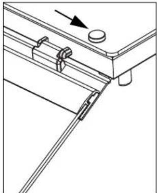
natural_image
Technical line drawing of a mechanical assembly with no visible text or symbolsnatural_image
Technical line drawing of a mechanical assembly with an inset showing a close-up of a bolt and nut (no text or symbols present)Instale los tapones
natural_image
Technical line drawing of a structural beam with mounting holes and support brackets (no text or symbols)
natural_image
Technical line drawing of a mechanical assembly with a cylindrical component and angled base (no text or symbols)natural_image
Technical line drawing of a mechanical bracket assembly with a knob and directional arrow (no text or symbols)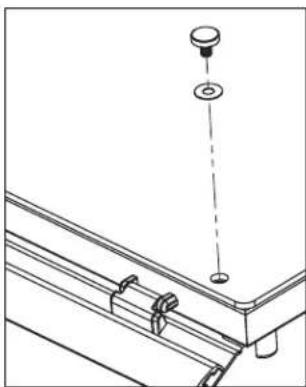
natural_image
Technical line drawing of a mechanical assembly with no visible text or symbolsnatural_image
Technical line drawing of a mechanical assembly with a pin and base plate (no text or symbols)- Retire el vidrio.

natural_image
Technical line drawing of a mechanical assembly with no visible text or symbolsnatural_image
Technical line drawing of a structural bracket with mounting holes and base plate (no text or symbols)natural_image
Technical line drawing of a mechanical bracket assembly with mounting holes and structural supports (no text or symbols)- Retire el vidrio.
natural_image
Technical line drawing of a structural support frame with three upward-pointing arrows indicating assembly or movement (no text or symbols present)natural_image
Technical line drawing of a mechanical frame assembly with mounting holes and dimension lines (no text or symbols)natural_image
Technical line drawing of a structural frame with supports and mounting points (no text or symbols)Instale la barra lastrada
natural_image
Technical line drawing of a mechanical assembly with no visible text or symbolsnatural_image
Technical line drawing of a mechanical assembly with no visible text or symbolsnatural_image
Technical line drawing of a mechanical assembly with two arrows indicating directional flow or force (no text or symbols present)natural_image
Technical line drawing of a mechanical assembly with a bracket and pivot point (no text or symbols)natural_image
Technical line drawing of a mechanical assembly with a hanging component and mounting bracket (no text or symbols)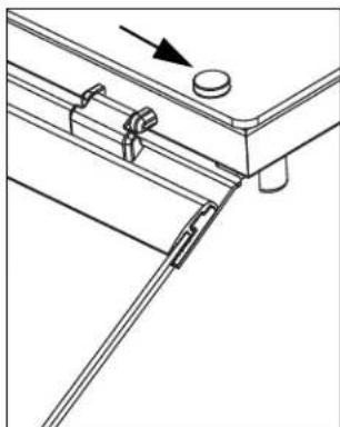
natural_image
Technical line drawing of a mechanical assembly with no visible text or symbolsnatural_image
Technical line drawing of a mechanical lifting or bracket assembly (no text or symbols)natural_image
Technical line drawing of a mechanical assembly with mounting brackets and a handle (no text or symbols)natural_image
Technical line drawing of a mechanical assembly with a valve and base plate (no text or symbols)natural_image
Technical line drawing of a mechanical bracket or frame structure (no text or symbols)natural_image
Line drawing of a cabinet or rack with a circular top and an arrow pointing downward (no text or symbols)natural_image
Pure technical diagram of a mechanical or structural assembly with no text, numbers, or symbolsnatural_image
Technical line drawing of a mechanical assembly with no visible text or symbolsnatural_image
Technical line drawing of a mechanical assembly with a tool and component (no text or symbols)natural_image
Technical line drawing of a mechanical bracket with mounting holes and a tool, showing no text or symbolsnatural_image
Technical line drawing of a mechanical bracket assembly (no text or symbols)natural_image
Technical line drawing of a mechanical assembly with no visible text or symbolsnatural_image
Technical line drawing of a mechanical assembly with no visible text or symbols
Outperform every day:
www.vollrath.com
The Vollrath Company, L.L.C.
1236 North 18th Street
- Low Profile Hinged Glass Breath Guards
- BREATH GUARD INSTALLATION
- Before You Begin
- Tools You Will Need
- Drill Mounting Holes
- Assemble and Mount the Breath Guard
- BREATH GUARD INSTALLATION (CONTINUED)
- If Your Breath Guard: Includes a heat strip and/or lights
- Does not include heat strips or lights
- Install the Glass Panels Long Side Panel(s)
- Short Side Panels
- For Double Sided Breath Guards
- For Single Sided Breath Guards
- Install the Glass Panels (Continued)
- Top Panel
- Install the Cover Plugs
- SINGLE-SIDED RETROFIT KIT INSTALLATION
- Remove the Top Glass
- Remove the End Panels
- Remove the Long Side Glass Panel
- SINGLE-SIDED RETROFIT KIT INSTALLATION (CONTINUED)
- Remove the Mounting Bracket
- Install the Ballast Bar
- Install the End Glass
- Reinstall the Top Glass
- End Profile of Single Sided Breath Guard
- HEAT STRIP INSTALLATION
- If this is a retrofit installation
- Installation
- LIGHT STRIP INSTALLATION
- INSTALLATION DU PARE-HALEINE
- Avant de commencer
- INSTALLATION DU PARE-HALEINE (SUITE)
- INSTALLATION DU KIT DE RATTRAPAGE UN CÔTÉ
- Matériel nécessaire
- INSTALLATION DU KIT DE RATTRAPAGE UN CÔTÉ (SUITE)
- Dépose du support
- INSTALLATION DE LA RAMPE CHAUFFANTE
- INSTALLATION DE LA RAMPE D'ÉCLAIRAGE
- Instale los tapones
- Instale la barra lastrada
Brand : Vollrath
Model : LP55280
Category : Buffet hygiene protection