
Caliber US12CB2BEA - Air Conditioning HAIER - Free user manual and instructions
Find the device manual for free Caliber US12CB2BEA HAIER in PDF.

| Product Type | Cassette split air conditioner (ductless) |
| Brand | Haier |
| Model | Caliber US12CB2BEA |
| Refrigerant | R454B (mildly flammable) |
| Cooling Capacity | 12000 BTU/h (estimated) |
| Power Supply | 230 V / 50 Hz, dedicated circuit |
| Dimensions (indoor unit) | Approximately 600 x 600 x 250 mm (without panel) |
| Weight (indoor unit) | Approximately 25 kg |
| Condensate Pump | Integrated, discharge head up to 120 cm |
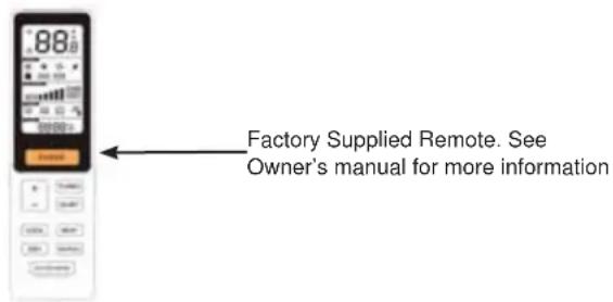
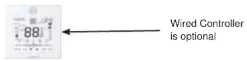
| Control | Infrared remote control (YR-HQ) and optional wired controller |
| Connectivity | Wi-Fi via SmartHQ app |
| Air Filter | Washable and reusable |
| Safety | Refrigerant leak sensor, automatic compressor shutdown |
| Parts Warranty | 10 years (registration required within 60 days) |
| Installation | By certified HVAC technician mandatory |
| Maintenance | Regular filter cleaning and annual inspection |
Frequently Asked Questions - Caliber US12CB2BEA HAIER
User questions about Caliber US12CB2BEA HAIER
0 question about this device. Answer the ones you know or ask your own.
Ask a new question about this device
Download the instructions for your Air Conditioning in PDF format for free! Find your manual Caliber US12CB2BEA - HAIER and take your electronic device back in hand. On this page are published all the documents necessary for the use of your device. Caliber US12CB2BEA by HAIER.
USER MANUAL Caliber US12CB2BEA HAIER
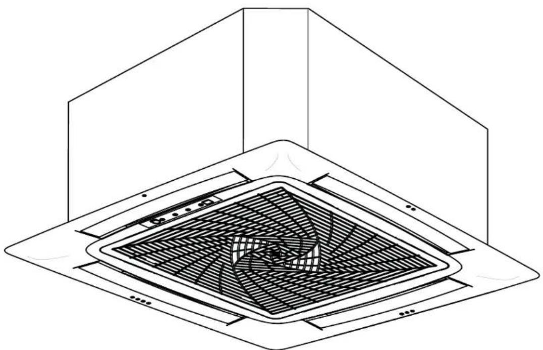
Installation Instructions Compact Cassette
natural_image
Isometric line drawing of a ceiling fan installation with internal blades and mounting brackets (no text or symbols)Design may vary by model number.
This installation manual is only printed in English. For French or Spanish version, please visit
GEAppliancesairandwater.com
IMPORTANT SAFETY INFORMATION....3
INSTALLATION INSTRUCTIONS....21
Step 1 25
Step 2 28
Step 3 30
Step 4 30
Step 5 31
LIMITED WARRANTY....33
RECORD KEEPING
Thank you for purchasing this product. This installation manual will help you get the best performance from your new heat pump.
For future reference, record the model and serial number located on the label on the side of your air conditioner/heat pump, and the date of purchase.
Staple your proof of purchase to this manual to aid in obtaining warranty service if needed.
To register your new Duct Free System go to
GEAppliancesAirandWater.com/Warranty and input the model/serial number information on this page. To receive a 10-year compressor and parts warranty, registration is required within 60 days of installation.
Model number
Serial number
Date of purchase

GE Appliances, Air and Water
IMPORTANT SAFETY INFORMATION READ ALL INSTRUCTIONS BEFORE USING THE APPLIANCE
WARNING
For your safety; the information in this manual must be followed to minimize the risk of fire,
electric shock, or personal injury.
- Use this equipment only for its intended purpose as described in this manual.
- This heat pump must be properly installed in accordance with these instructions before it is used.
- All wiring should be rated for the amperage value listed on the rating plate. Use only copper wiring.
- All electrical work must be completed by a qualified electrician and completed in accordance with local and national building codes.
For any service which requires entry into the refrigerant sealed system, Federal regulations require that the work is performed by a technician having a Class II or Universal certification.
- All air conditioners contain refrigerants, which under federal and/or local law must be removed prior to product disposal. If you are getting rid of an old product with refrigerants, check with the company handling disposal.
- These R454B heat pumps systems require that contractors and technicians use tools, equipment and safety standards approved for use with this refrigerant.
- DO NOT use equipment certified for R22,R32 or R410A refrigerant only.
WARNING
RISK OF ELECTRIC SHOCK. Could cause injury or death.
- An adequate ground is essential before connecting the power supply or charging with refrigerant.
- Disconnect all connected electric power supplies before servicing.
- Aluminum building wiring may present special problems - consult a qualified electrician.
- The surrounding conditions (ambient temperature, direct sunlight, and rainwater) shall be noticed during electrical wiring, with effective protective measures being taken.
- The dedicated branch circuit must be used, and leakage protector with sufficient capacity must be installed.
• Repair or replace immediately all electrical wiring that
has become frayed or otherwise damaged. Do not use wiring that shows cracks or abrasion damage along its length or at either end.
- When the unit is in the STOP position, there is still voltage to the electrical controls.
- Copper wire cable in line with local standards shall be used as the power line and connector wire.
- Both the indoor unit and outdoor unit shall be reliably earthed.
- Wiring for the outdoor unit shall be made first and then the indoor unit. The air conditioner can only be powered on after wiring and pipe connection.
WARNING
RISK OF FIRE. Could cause injury or death.
- Do not store or use combustible materials, gasoline or other flammable vapors or liquids in the vicinity of this or any other appliance.
ATTENTION
- Please do not use extension cords in this system.
- Aluminum building wiring may have special problems, please consult a licensed electrician.
- If the unit has the leak detection system installed, the unit must be powered except for service.
READ AND SAVE THESE INSTRUCTIONS
IMPORTANT SAFETY INFORMATION READ ALL INSTRUCTIONS BEFORE USING THE APPLIANCE
For more help, visit geappliancesairandwater.com or call the technical support line at 1.844.487.9443
BEFORE YOU BEGIN
Read these instructions completely and carefully.
- IMPORTANT — Save these instructions for local inspector's use.
. IMPORTANT — Observe all governing codes and ordinances. - Note to installer – Be sure to leave these instructions with the Consumer.
- Note to consumer – Keep these instructions for future reference.
- Skill level – A licensed certified technician (to handle refrigerant, recovery, etc) and a qualified electrician are required for installation and service of this split heat pump system.
- Use team lift for mounting the ducted unit.
- Proper installation is the responsibility of the installer.
- Product failure due to improper installation is not covered under the limited warranty.
- For personal safety, this system must be properly grounded.
- Protective devices (fuses or circuit breakers) acceptable for installation are specified on the nameplate of each unit.
- Make sure to minimize wiring or plumbing inside the wall when installing.
WARNING
- This product is not intended for use by persons (including children) with reduced physical, sensory or mental capabilities, or lack of experience and knowledge, unless they have been given supervision or instruction concerning use of the appliance by a person responsible for their safety.
- Children should be supervised to ensure that they do not play with the product.
- Ensure that the unit shall be installed in accordance with local and national wiring codes.
- For the dimensions of the space necessary for correct installation of the appliance, including the minimum permissible distances to adjacent structures, refer to this document.
- Ensure only approved units are connected together and that all refrigerant line dimensions and refrigerant charging requirements are followed to prevent exceeding the maximum operating pressure.
- ONLY connect units that are labeled with the same refrigerant.
- Any damage of electrical supply must be replaced by the manufacturer, its service agent or similarly qualified persons in order to avoid a hazard.
- Means for disconnection must be incorporated in the fixed wiring in accordance with wiring rules. Disconnect ampere rating must be at least 115% of the Minimum Circuit Ampacity listed on the rating plate for this product. Disconnect must be installed within sight and readily accessible. Refer to local and national electric code for any additional requirements specified in your region of install.
Safety Awareness
- Procedures: Operation shall be made as per controlled procedures to minimize the probability of risks.
- Area: Area shall be divided and isolated appropriately, and operation in an enclosed space shall be avoided. Before the refrigeration system is started or energized, ventilation or opening of the area shall be guaranteed.
- Site inspection: The refrigerant shall be checked.
- Fire control: A fire extinguisher and a "No Smoking" sign shall be placed in the installation area during installation. The installation area shall remain free from fire/ignition sources during installation.
READ AND SAVE THESE INSTRUCTIONS
IMPORTANT SAFETY INFORMATION READ ALL INSTRUCTIONS BEFORE USING THE APPLIANCE
Unpacking Inspection
Indoor unit: nitrogen is sealed during the delivery of indoor units (inside the evaporator), and the red sign at the top of the green plastic seal cap on the evaporator air pipes of the indoor unit shall be checked first after unpacking. In case the sign is raised, the nitrogen sealed still exists. Afterwards, the black plastic seal cap at the joint of evaporator liquid pipes of the indoor unit shall be pressed, to check whether nitrogen still exists. In case no nitrogen is released, ensure the indoor unit does not have a leak before continuing with installation.
Inspection on Installation Environment
- Power supply, switches or other high-temperature articles such as the ignition source and oil heater shall be avoided below the indoor unit.
- The power supply shall be provided with grounding wire and be reliably grounded.
- User shall verify in advance whether water/electricity/gas pipelines are hidden in the wall in locations that may be punctured with an electric drill. It is recommended that the through-wall holes reserved shall be used as much as possible.
Safety Principles of Installation
- Favorable ventilation shall be maintained at the place of installation (doors and windows are opened).
- Open fire or high-temperature heat source (including welding, smoking and oven) higher than 548^ F is not allowed within the scope of flammable refrigerant.
- Anti-static measures shall be taken, such as the wearing of cotton clothes and cotton gloves.
- The place of installation shall be convenient for installation or maintenance and cannot be adjacent to heat source and flammable and combustible environment.
- In case of refrigerant leakage of the indoor unit during installation, the valve of the outdoor unit shall be closed immediately, and windows shall be opened, and all the personnel shall be evacuated. After the leakage of refrigerant is handled, the indoor environment shall be subject to concentration detection. Further handling is not allowed until the safety level is reached.
- In case the product is damaged, it must be delivered to the maintenance point. Welding of refrigerant pipelines at the user's site is not allowed.
- The installation position of air conditioner shall be convenient for installation or maintenance. Barriers shall be avoided around the air inlet/outlet of the indoor/outdoor unit, and the electrical appliance, power switches, sockets, valuables, and high-temperature products within the scope of both sidelines of the indoor unit shall be avoided.
CAUTION
- Refrigerant should be only added or removed by a licensed HVAC technician.
- Before adding additional refrigerant, perform air purging from the refrigerant pipes and indoor unit using a vacuum pump, then charge additional refrigerant.
READ AND SAVE THESE INSTRUCTIONS
Requirements for Operation, Service and Installation of Appliances Using Flammable Refrigerants
WARNING
- Do not use means to accelerate the defrosting process or to clean, other than those recommended by the manufacturer.
- The appliance shall be stored in a room without continuously operating ignition sources (for example: open flames, an operating gas appliance or an operating electric heater.
- Do not pierce or burn.
- Be aware that refrigerants may not contain an odor.
Warning; Flammable Materials, Refrigerant class per ISO 817

Owner's Manual; Operating Instructions

Read Owner's Manual

Service Indicator; Read Technical Manual
General
– During installation, due to the extended refrigerant pipes, additional REFRIGERANT may be charged. Please complete the REFRIGERANT label provided in the manual, and securely paste it near the appliance marking.
- Handling, installation, cleaning, servicing and disposal of refrigerant must comply with the local regulation and the instruction.
– Servicing shall be performed only as recommended by the manufacturer.
- Spaces where refrigerant pipes are allowed shall comply with the below requirement:
- that piping material, pipe routing, and installation shall include protection from physical damage in operation and service, and be in compliance with national and local codes and standards, such as ASHRAE 15, IAPMO Uniform Mechanical Code, ICC International Mechanical Code, or CSA B52. All field joints shall be accessible for inspection prior to being covered or enclosed.
- that the installation of pipe-work shall be kept to a minimum.
- that mechanical connections made at joints that made in the installation between parts of the refrigerating system in shall be accessible for maintenance purposes.
- that protection devices, piping, and fittings shall be protected as far as possible against adverse environmental effects, for example, the danger of water collecting and freezing in relief pipes or the accumulation of dirt and debris.
- that piping in refrigeration systems shall be so designed and installed to minimize the likelihood of hydraulic shock damaging the system.
- that precautions shall be taken to avoid excessive vibration or pulsation.
Requirements for Operation, Service and Installation of Appliances Using Flammable Refrigerants
General (cont.)
- that after completion of field piping for split systems, the field pipework shall be pressure tested with an inert gas and then vacuum tested prior to refrigerant charging, according to the following requirements:
- The minimum test pressure for the low side of the system shall be the low side design pressure and the minimum test pressure for the high side of the system shall be the high side design pressure, unless the high side of the system, cannot be isolated from the low side of the system in which case the entire system shall be pressure tested to the low side design pressure.
- The test pressure after removal of pressure source shall be maintained for at least 1 hour with no decrease of pressure indicated by the test gauge, with test gauge resolution not exceeding 5% of the test pressure.
- During the evacuation test, after achieving a vacuum level specified in the manual or less, the refrigeration system shall be isolated from the vacuum pump and the pressure shall not rise above 1500 microns within 10 min. The vacuum pressure level shall be specified in the manual, and shall be the lessor of 500 microns or the value required for compliance with national and local codes and standards, which may vary between residential, commercial, and industrial buildings.
- that field-made refrigerant joints indoors shall be tightness tested according to the following requirements: The test method shall have a sensitivity of 5 grams per year of refrigerant or better under a pressure of at least 0.25 times the maximum allowable pressure. No leak shall be detected.
Qualification of workers
The manual shall contain specific information about the required qualification of the working personnel for maintenance, service and repair operations. Every working procedure that affects safety means shall only be carried out by competent persons.
Examples for such working procedures are:
- breaking into the refrigerating circuit;
- opening of sealed components;
- opening of ventilated enclosures.
The competent persons are trained by the national training organizations or manufacturers that are accredited to teach the relevant national competency standards that may be set in legislation. The achieved competence should be documented by a certificate.
Information on servicing
Prior to beginning work on systems containing FLAMMABLE REFRIGERANTS, safety checks are necessary to ensure that the risk of ignition is minimized. For repair to the REFRIGERATING SYSTEM, the below requirement shall be completed prior to conducting work on the system:
- Work shall be undertaken under a controlled procedure so as to minimise the risk of a flammable gas or vapor being present while the work is being performed.
- All maintenance staff and others working in the local area shall be instructed on the nature of work being carried out. Work in confined spaces shall be avoided.
- The area shall be checked with an appropriate refrigerant detector prior to and during work, to ensure the technician is aware of potentially toxic or flammable atmospheres. Ensure that the leak detection equipment being used is suitable for use with all applicable refrigerants, i. e. non-sparking, adequately sealed or intrinsically safe.
- If any hot work is to be conducted on the refrigerating equipment or any associated parts, appropriate fire extinguishing equipment shall be available to hand. Have a dry powder or CO2 fire extinguisher adjacent to the charging area.
Requirements for Operation, Service and Installation of Appliances Using Flammable Refrigerants
Information on servicing (cont.)
- No person carrying out work in relation to a REFRIGERATING SYSTEM which involves exposing any pipe work shall use any sources of ignition in such a manner that it may lead to the risk of fire or explosion. All possible ignition sources, including cigarette smoking, should be kept sufficiently far away from the site of installation, repairing, removing and disposal, during which refrigerant can possibly be released to the surrounding space. Prior to work taking place, the area around the equipment is to be surveyed to make sure that there are no flammable hazards or ignition risks. "No Smoking" signs shall be displayed.
- Ensure that the area is in the open or that it is adequately ventilated before breaking into the system or conducting any hot work. A degree of ventilation shall continue during the period that the work is carried out. The ventilation should safely disperse any released refrigerant and preferably expel it externally into the atmosphere.
- Where electrical components are being changed, they shall be fit for the purpose and to the correct specification. At all times the manufacturer's maintenance and service guidelines shall be followed. If in doubt, consult the manufacturer's technical department for assistance.
- The following checks shall be applied to installations using FLAMMABLE REFRIGERANTS:
- marking to the equipment continues to be visible and legible. Markings and signs that are illegible shall be corrected;
- refrigerating pipe or components are installed in a position where they are unlikely to be exposed to any substance which may corrode refrigerant containing components, unless the components are constructed of materials which are inherently resistant to being corroded or are suitably protected against being so corroded.
– Repair and maintenance to electrical components shall include initial safety checks and component inspection procedures. If a fault exists that could compromise safety, then no electrical supply shall be connected to the circuit until it is satisfactorily dealt with. If the fault cannot be corrected immediately but it is necessary to continue operation, an adequate temporary solution shall be used. This shall be reported to the owner of the equipment so all parties are advised.
– Initial safety checks shall include:
- that capacitors are discharged: this shall be done in a safe manner to avoid possibility of sparking;
- that no live electrical components and wiring are exposed while charging, recovering or purging the system;
• that there is continuity of earth bonding.
Repairs to sealed components, intrinsically safe components
- Sealed electrical components shall be replaced.
– Intrinsically safe components must be replaced.
– Replace components only with parts specified by the manufacturer. Other parts may result in the ignition of refrigerant in the atmosphere from a leak.
Cabling
Check that cabling will not be subject to wear, corrosion, excessive pressure, vibration, sharp edges or any other adverse environmental effects. The check shall also take into account the effects of aging or continual vibration from sources such as compressors or fans.
Requirements for Operation, Service and Installation of Appliances Using Flammable Refrigerants
Detection of flammable refrigerants
- Under no circumstances shall potential sources of ignition be used in the searching for or detection of refrigerant leaks. A halide torch (or any other detector using a naked flame) shall not be used.
- The following leak detection methods are deemed acceptable for all refrigerant systems.
- Electronic leak detectors may be used to detect refrigerant leaks but, in the case of FLAMMABLE
REFRIGERANTS, the sensitivity may not be adequate, or may need re-calibration. (Detection equipment shall be calibrated in a refrigerant-free area.) Ensure that the detector is not a potential source of ignition and is suitable for the refrigerant used. Leak detection equipment shall be set at a percentage of the LFL of the refrigerant and shall be calibrated to the refrigerant employed, and the appropriate percentage of gas (25 % maximum) is confirmed.
- Leak detection fluids are also suitable for use with most refrigerants but the use of detergents containing chlorine shall be avoided as the chlorine may react with the refrigerant and corrode the copper pipe-work.
NOTE: Examples of leak detection fluids are:
- bubble method,
- fluorescent method agents.
- If a leak is suspected, all naked flames shall be removed/extinguished.
- If a leakage of refrigerant is found which requires brazing, all of the refrigerant shall be recovered from the system, or isolated (by means of shut off valves) in a part of the system remote from the leak. Removal of refrigerant shall be according to the manual.
Removal and evacuation
- When breaking into the refrigerant circuit to make repairs – or for any other purpose – conventional procedures shall be used. However, for flammable refrigerants it is important that best practice be followed, since flammability is a consideration. The following procedure shall be adhered to:
a) safely remove refrigerant following local and national regulations;
b) purge the circuit with inert gas;
c) open the circuit by cutting or brazing.
- The refrigerant charge shall be recovered into the correct recovery cylinders if venting is not allowed by local and national codes. For appliances containing flammable refrigerants, the system shall be purged with oxygen-free nitrogen to render the appliance safe for flammable refrigerants. This process might need to be repeated several times.
- Compressed air or oxygen shall not be used for purging refrigerant systems.
Charging procedures
– In addition to conventional charging procedures, the following requirements shall be followed.
- Ensure that contamination of different refrigerants does not occur when using charging equipment. Hoses or lines shall be as short as possible to minimise the amount of refrigerant contained in them.
- Cylinders shall be kept in an appropriate position according to the instructions.
- Ensure that the REFRIGERATING SYSTEM is earthed prior to charging the system with refrigerant.
- Label the system when charging is complete (if not already).
– Extreme care shall be taken not to overfill the REFRIGERATING SYSTEM.
- Prior to recharging the system, it shall be pressure-tested with the appropriate purging gas. The system shall be leak-tested on completion of charging but prior to commissioning. A follow up leak test shall be carried out prior to leaving the site.
Requirements for Operation, Service and Installation of Appliances Using Flammable Refrigerants
Decommissioning
– Before carrying out this procedure, it is essential that the technician is completely familiar with the equipment and all its detail. It is recommended good practice that all refrigerants are recovered safely. Prior to the task being carried out, an oil and refrigerant sample shall be taken in case analysis is required prior to re-use of recovered refrigerant. It is essential that electrical power is available before the task is commenced.
a) Become familiar with the equipment and its operation.
b) Isolate system electrically.
c) Before attempting the procedure, ensure that:
- mechanical handling equipment is available, if required, for handling refrigerant cylinders;
- all personal protective equipment is available and being used correctly;
- the recovery process is supervised at all times by a competent person;
- recovery equipment and cylinders conform to the appropriate standards.
d) Pump down refrigerant system, if possible.
e) If a vacuum is not possible, make a manifold so that refrigerant can be removed from various parts of the system.
f) Make sure that cylinder is situated on the scales before recovery takes place.
g) Start the recovery machine and operate in accordance with instructions.
h) Do not overfill cylinders (no more than 80 % volume liquid charge).
i) Do not exceed the maximum working pressure of the cylinder, even temporarily.
j) When the cylinders have been filled correctly and the process completed, make sure that the cylinders and the equipment are removed from site promptly and all isolation valves on the equipment are closed off.
k) Recovered refrigerant shall not be charged into another REFRIGERATING SYSTEM unless it has been cleaned and checked.
Labeling
– Equipment shall be labeled stating that it has been de-commissioned and emptied of refrigerant. The label shall be dated and signed. For appliances containing FLAMMABLE REFRIGERANTS, ensure that there are labels on the equipment stating the equipment contains FLAMMABLE REFRIGERANT.
Requirements for Operation, Service and Installation of Appliances Using Flammable Refrigerants
Recovery
- When removing refrigerant from a system, either for servicing or decommissioning, it is recommended good practice that all refrigerants are removed safely.
- When transferring refrigerant into cylinders, ensure that only appropriate refrigerant recovery cylinders are employed. Ensure that the correct number of cylinders for holding the total system charge is available. All cylinders to be used are designated for the recovered refrigerant and labelled for that refrigerant (i. e. special cylinders for the recovery of refrigerant). Cylinders shall be complete with pressure-relief valve and associated shut-off valves in good working order. Empty recovery cylinders are evacuated and, if possible, cooled before recovery occurs.
- The recovery equipment shall be in good working order with a set of instructions concerning the equipment that is at hand and shall be suitable for the recovery of all appropriate refrigerants including, when applicable, FLAMMABLE REFRIGERANTS. In addition, a set of calibrated weighing scales shall be available and in good working order. Hoses shall be complete with leak-free disconnect couplings and in good condition. Before using the recovery machine, check that it is in satisfactory working order, has been properly maintained and that any associated electrical components are sealed to prevent ignition in the event of a refrigerant release. Consult manufacturer if in doubt.
- The recovered refrigerant shall be returned to the refrigerant supplier in the correct recovery cylinder, and the relevant waste transfer note arranged. Do not mix refrigerants in recovery units and especially not in cylinders.
- If compressors or compressor oils are to be removed, ensure that they have been evacuated to an acceptable level to make certain that FLAMMABLE REFRIGERANT does not remain within the lubricant. The evacuation process shall be carried out prior to returning the compressor to the suppliers. Only electric heating to the compressor body shall be employed to accelerate this process. When oil is drained from a system, it shall be carried out safely.
CONSIGNES DE SÉCURITÉ IMPORTANTES LISEZ TOUTES LES INSTRUCTIONS AVANT D'UTILISER L'APPAREIL
▲AVERTISSEMENT
Required Tools for Installation
- 17mm, 22mm, 26mm or Adjustable Wrench
• #2 Phillips Screwdriver - Drill
- 45° Flaring Tool
- Hex Wrench
- Hole Saw 2 34 "
- Level
- Manifold Gauge
- Measuring Tape
- Micron Gauge
-
Mini-Split Adapter (5/16"F to 1/4"M)
-
Nitrogen (consumable)
- Pipe Cutter
- Razor Knife
- Reamer
- Sealant, non-expanding (for lineset hole)
- Soap/water solution or gas leakage detector
- Stud Finder
- Torque Wrench
- Vacuum Pump
- Wire Strippers
Supplied with Unit
- Condensate connecting tube
- Clamp
-
Flare nuts
-
YR-HQ remote (batteries included)
- Insulation
- Mounting Template
Supplied by Installer
| Model Liquid (inch) | Vapor (inch) | |
| US09CB2BEA | 1/4 | 3/8 |
| US12CB2BEA | 1/4 | 3/8 |
| US18CB2BEA | 1/4 | 1/2 |
• Insulated copper tubing
- 14/4 (14 gauge – 4 conductor) AWG SOOW Non-Shielded Stranded Copper Cable
• 3/4 inch PVC for condensate
• Insulation for condensate drain
• 3/8 threaded rod, washers and nuts
- 16/2 AWG Shielded SOOW Cable for high speed communication
• R454B Refrigerant
Cassette Product Information
The Cassette Indoor Air Handler ships consists of a cassette assembly and operational louver. The Cassette Indoor Unit is operated via a factory supplied remote control. A wired controller is optional.
The Cassette unit will install between standard dropped ceiling grids. It is mounted using threaded rods that fit into brackets that are located at all four corners of the cassette assembly.
The Cassette unit receives 230 volt line voltage from a connection at the outdoor condensing unit. There is no requirement for independent line voltage connections.
The cassette unit has a built in condensate pump and associated float switch that manages the operation of the condensate pump. A flexible hose is included with the Cassette unit. This hose connects the cassette condensate drain outlet to the buildings condensate drain system.
The motorized louver is controlled via the remote control. The louver has indicator lights that communicate function and diagnostic information to the user and service technician.
Factory provided insulating tape is included with the cassette unit. This tape should be placed over the refrigerant piping connections at the indoor unit to prevent sweating.
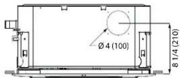
Fresh Air Intake Option
The cassette has a marked area to cut out if outside air is desired. The piping connection should be made with a 4 inch diameter pipe. Outside air should be pre-filtered prior to entry into the cassette.
Condensate Handling
The Cassette unit has a built in condensate pump and water level safety switch. There is no option for gravity drain. The condensate pump is rated to lift water up to 47 3/16" from the point of discharge on the cassette assembly. Recommended pump flow rate is 0.106 gpm to 0.159 gpm.
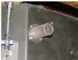
natural_image
Close-up of a mechanical component with a transparent cylindrical part inserted, mounted on a dark surface (no visible text or symbols)The cassette unit comes with a grey connection hose with clamp. This hose is connected to the cassette assembly discharge hose port. The other end of the hose is sized to accept 3/4 "PVC piping. Recommended condensate piping configurations are shown here:
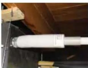
natural_image
Close-up of a white cylindrical object mounted on a dark surface, with wooden beams and no visible text or symbols.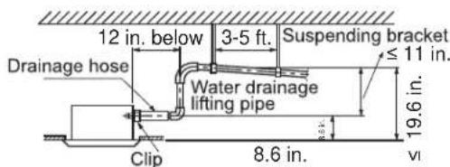
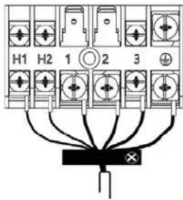
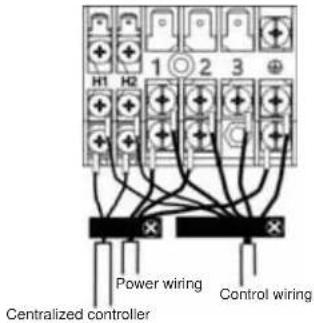
Electrical Power
Follow all local codes and regulations when installing electrical wiring.
Route required electrical power to area where the Cassette unit is to be located. Maintain at least a 10 foot separation between TV, Radio or any communication wiring and the power to the indoor unit.
14/4 AWG SOOW Non-Shielded Stranded Copper Cable should be used to make the electrical connection and communication link between indoor and outdoor units.
16/2 AWG Shielded SOOW Cable should be used for high speed communication on H1 and H2 terminals. Note: In applications with multiple indoor units, only connect one indoor unit to the outdoor unit with the high speed communication cable. It is recommended to connect the indoor unit that is closest to the outdoor unit.
The wiring is connected at the indoor unit electrical terminal blocks screws 1, 2, 3 and ground. There should be no splices in the wires between the indoor and outdoor units as these serve as communication signal wires and electrical power connections. Any accessory added to shut off power to the indoor section should break the Number 2 terminal only.
natural_image
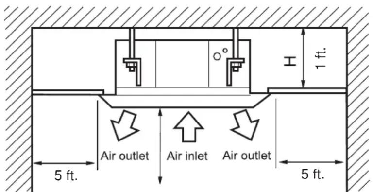
Close-up of hands using a tool to adjust or install electronic components with visible wires and connectors (no text or symbols)Air Delivery Clearances
Make certain to maintain proper clearances around the cassette as specified in the installation instructions. Standard clearances for cassette air handlers require 5 feet of clearance in each direction. There should be 8 feet of clearance from the face of the cassette grille to the floor. Inadequate clearances can cause system freezing and temperature control problems.
Service and Maintenance Clearances
Make sure there are adequate clearances for future maintenance and service. Allow enough room to access the condensate pump assembly and the electrical control box.
MINIMUM CLEARANCES (Appearance may vary)
This picture is for reference only. Your product may look different.
8 ft. Over
Step 1 - Preparation
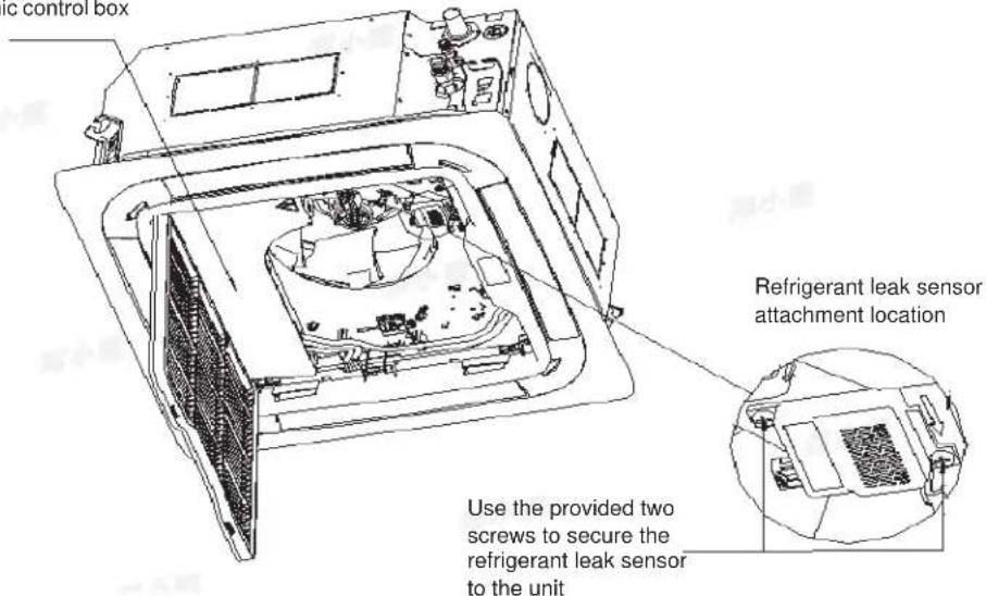
A. Before installing the indoor unit, determine if a refrigerant leak sensor is required.
Refer to the outdoor unit installation instructions for calculating the total refrigerant charge. Measure the area of the space that will be conditioned by the indoor unit, and refer to the below table :
| Compact Cassette without Refrigerant Leak Sensor Installed1 | |||||||||||||||
| Maximum Refrigerant Charge | Ibs ≤3.9 4 4.5 5 5.5 6 6.5 7 7.5 8 8.5 9 | ||||||||||||||
| oz ≤62.4 64 72 80 88 96 104 11 12 120 | 128 136 144 | ||||||||||||||
| Minimum Room Size ft2 | No restriction 59 67 74 82 89 97 104 11 12 119 127 134 | ||||||||||||||
If your room size is smaller than the minimum room size listed above, a refrigerant leak sensor may be required. See below table:
| Compact Cassette with Refrigerant Leak Sensor Field-Installed ^1 | |||||||||||||
| Maximum Charge | Ibs ≤ 3.9 | 4 | 4.5 | 5 | 5.5 | 6 | 6.5 | 7 | 7.5 | 8 | 8.5 | 9 | |
| oz ≤ 62.4 | 64 | 72 | 80 | 88 | 96 | 104 | 112 | 120 | 128 | 136 | 144 | ||
| Minimum Room Size | ft ^2 | No restriction | 60 | 68 | 75 | 83 | 90 | 98 | 105 | ||||
Installation in rooms smaller than the minimum sizes listed above are not allowed based on the standard of UL60335-2-40 Edition 4 ^4 .
1: Calculated based on a minimum install height of 7 ft 2-3/4 inches (2.2m) measured from the floor to the bottom of the indoor unit.
2: UL60335-2-40 Edition 4 has been adopted by majority of state and local codes. A limited number of local and state codes may require compliance to UL 60335-2-40 Edition 3. Please refer to our website at GEAppliancesAirandWater.com for guidance on installations in those localities.
Note: Additional room area may be needed for different installation altitudes. Please use Altitude Adjustment Factor table below by multiplying minimum room size by the altitude adjustment factor based on install altitude.
Altitude Adjustment Factor
| Altitude (m) | 0 | 200 | 400 | 600 | 800 | 1000 | 1200 | 1400 | 1600 |
| Altitude (ft) | 0 | 660 | 1310 | 1970 | 2620 | 3280 | 3940 | 4590 | 5250 |
| Adj. Factor | 1 | 1 | 1 | 1 | 1.02 | 1.05 | 1.04 | 1.1 | 1.12 |
| Altitude (m) | 1600 | 1800 | 2000 | 2200 | 2400 | 2600 | 2800 | 3000 | 3200 |
| Altitude (ft) | 5250 | 5910 | 6560 | 7220 | 7870 | 8530 | 9190 | 9810 | 10500 |
| Adj. Factor | 1.12 | 1.15 | 1.18 | 1.21 | 1.25 | 1.28 | 1.32 | 1.36 | 1.4 |
B. If leak sensor is not needed, make sure to flip dip switch 1-5 to ON.
Missing this step will result getting error code bA.
If leak sensor is needed, please go to step C.
Step 1 - Preparation (cont)
C. Install the Leak Sensor
Step 1: Press down the locks located on the panel.
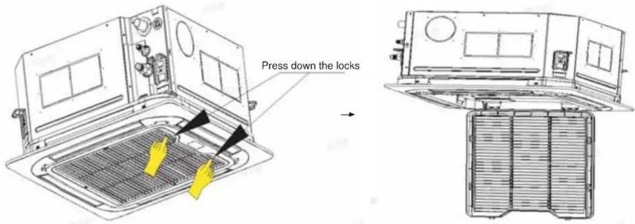
Step 2: Open the air inlet grille.
Electronic control box
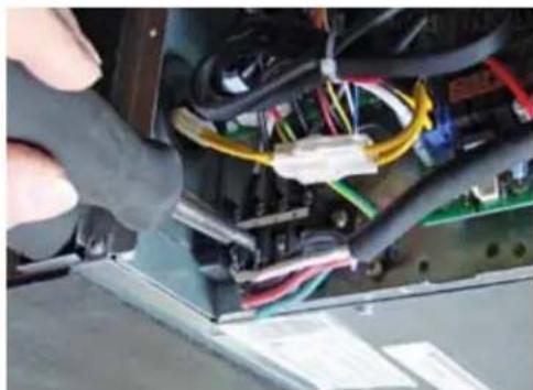
Step 3: Wiring for the sensor is already present. Plug refrigerant leak sensor into the wire connected to CN23.
Step 4: Close the air inlet grille.
Step 1 - Preparation (cont)
D. Procedure for selecting the location:
- Place above the ceiling where you have enough space to position the unit.
- Place where the drainage pipe can be properly positioned.
- Place where the inlet and outlet air of the indoor unit will not be blocked.
- Do not install the unit in a place with heavy oil or moisture (e.g. - kitchens and workshops)
- Do not install in a location with destructive gas (such as sulfuric acid gas) or pungent gas (thinner and gasoline) are used or stored.
- Choose a place solid enough to bear the weight and vibration of the unit and where the operation noise will not be amplified.
• Install where there are no expensive items like a television or piano below the indoor unit.
- Leave enough space for maintenance.
- Install at least 3 ft. away from televisions and radios to avoid interference.
NOTES:
- R454B refrigerant is a mildly flammable refrigerant. However, if there is a concern about a dangerous level of refrigerant concentration in the case of refrigerant leakage, add extra ventilation.
E. Threaded Rod Mounting Information:
The Cassette unit should be mounted to the building structure using threaded rods. The threaded rods should have washers and nuts to allow the height and level of the cassette to be adjusted.
The threaded rods and attachment brackets are field supplied items. The materials required for mounting to the brackets on the cassette assembly include:
• 4-3/8" Threaded Rods
• 4- Mounting Brackets
- 8-Washers
• 8- Nuts (Double nut the assembly as shown)
natural_image
Interior view of a ceiling-mounted industrial or mechanical fixture with transparent glass panels and mounted components (no visible text or symbols)Step 2 - Installation of the Cassette Unit
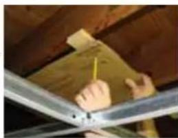
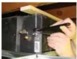
A. Use supplied cardboard template to locate center point of cassette for mounting. Use a plumb bob and string to position cassette by referencing center hole of template. Mark the mounting positions of the threaded rods using the guides on the cardboard template.
natural_image
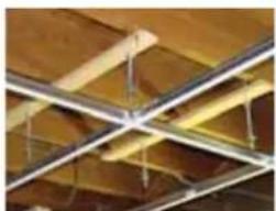
Close-up of hands installing or adjusting a wooden beam under a ceiling structure (no visible text or symbols)B. Install threaded rods to structure using appropriate fasteners.
natural_image
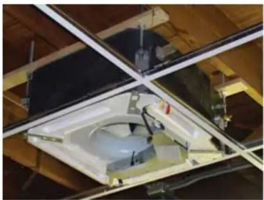
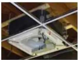
Close-up of ceiling light fixtures with diagonal metal beams and recessed lighting (no text or symbols visible)C. Lift the cassette and position the threaded rods into the 4 mounting clips on each corner of the cassette unit.
natural_image
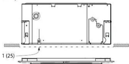
Interior view of a room with ceiling fixtures and a central object (no visible text or symbols)One Inch Recess:
1 inch recess between ceiling surface ad bottom of unit without panel on.
D. Install threaded rods to structure using appropriate fasteners.
natural_image
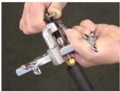
Close-up of hands using a tool to adjust or install a mechanical component (no visible text or symbols)E. Prior to routing the refrigerant lines to the unit, install the supplied flare nuts onto the refridergent lines. Using a R454B flaring tool, flare the refrigerant lines. Remove the caps attached to the ends of the refrigerant line connections at the cassette. A nitrogen charge will leak out.
Using a torque wrench, torque the fittings to the proper specifications. (See outdoor Unit Section for flare torque settings.)
natural_image
Close-up of hands using a mechanical tool to adjust or install a component (no visible text or symbols)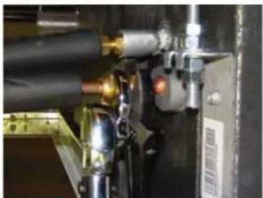
natural_image
Close-up of industrial machinery components with no visible text or symbolsF. Connect the grey flexible drain hose supplied with the cassette unit to the condensate pump discharge pipe of the cassette. Tighten the clamp securely. Using the 3/4" PVC, connect the flexible hose to the building's condensate drain system.

natural_image
Close-up of a white cylindrical object mounted on a metal frame, with wooden beams and no visible text or symbols.Step 2 - Installation of the Cassette Unit (Cont.)
G. Remove the electrical box cover. Remove the rubber grommet and insert a 1/2 inch electrical connector and reducing washer. Route electrical wiring into cassette unit. Connect to wire terminals as indicated in wiring diagram (use 14/4 AWG SOOW Non-Shielded Stranded Copper Cable for power and main communication line; use 16/2 AWG Shielded SOOW Cable for high speed communication).
natural_image
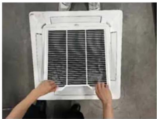
Close-up of a hand inserting electronic components into an air conditioner unit (no visible text or symbols)H. Connect Grille assembly to cassette assembly. Connect wires from louver to the harness on the cassette assembly. There are two wire connections (see photo for connections).
- Secure louver with four screws.
- Reinstall electrical box cover.
• Install return air grille into louver assembly.
• Installation is now complete.
natural_image
Person installing or adjusting a wall-mounted air conditioner unit with visible circuit board (no text or symbols)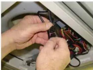
natural_image
Close-up of hands installing or adjusting wires on a device (no visible text or symbols)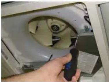
natural_image
Hand holding a handheld device inside a refrigerator (no visible text or symbols)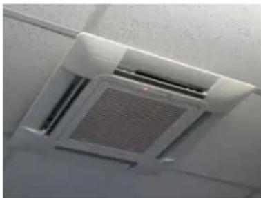
natural_image
Close-up of a white ceiling HVAC grille with a mesh grille and ventilation duct (no text or symbols visible)Step 3 - Electrical Connections
Electrical connections indoor and outdoor units
• 14 AWG AWG SOOW Non-Shielded Stranded Copper Wire Only. (Central Controller Not Used)
- 16/2 AWG Shielded SOOW Cable should be used for high speed communication on H1 and H2 terminals. Note: In applications with multiple indoor units, only connect one indoor unit to the outdoor unit with the high speed communication cable. It is recommended to connect the indoor unit that is closest to the outdoor unit.
- Maintain 10 feet of separation between TV and any Radio wiring.
Indoor Unit Control Wiring
Outdoor Unit
Step 4 - Leak Testing, Evacuation and Wifi
Refer to the outdoor Installation Manual for the recommended procedure.
Wifi Pairing
- Download the "SmartHQ" app from Google Play (Android) or the Apple app store (IOS).
After downloading the App:
- Open the app.
- Select "Sign In".
- Sign into your account or register as a new user.
- Select the "+" icon to add a new device and follow the directions in the app.

Software Notice
To ensure product is functioning optimally and with the latest feature set, connect AC unit to WiFi and update with latest software. Refer to Owner's Manual on how to connect WiFi.
Step 5 - Final Check
Final Check
Start Up Checklist
☐ Refrigerant charge is verified and system has been leak tested
□ Line sets have been insulated
□ Electrical connections are secure
□ Electrical ground has been checked and verified
□ Electrical wiring terminals match at indoor and outdoor unit
☐ Wire between outdoor and indoor must be 14/4 AWG SOOW Non-Shielded Stranded Copper Cable for power and main communication cable
☐ Wire between outdoor and indoor must be 16/2 AWG Shielded SOOW Cable for high speed communication if unit is primary indoor unit
☐ Outdoor to indoor wires 1, 3, and Ground are free of splices
☐ Condensate drain has correct pitch and has been leak tested insulated to avoid condensate.
- Verify 100% pump reservoir drains to avoid risks of leaks.
☐ Check reservoir for any contaminates from installation that could promote bacteria growth
□ Indoor and outdoor units are compatible
□ Indoor and outdoor units are firmly mounted
☐ Power source voltage is within +/- 10% tolerances
☐ The indoor and outdoor sections are quiet and free of vibration
☐ All functions of the controller have been verified
☐ Operation in cooling or heating modes is normal (see sequence of operation in service manual)
☐ Operation of the system has been explained to the owner
□ Indoor unit capacity check has been completed
Verify Refrigerant Leak Sensor Function
When a refrigerant leak or other leak sensor related error is detected, the indoor fan will turn on at high speed, and the compressor on the outdoor unit will turn off. These functions can be verified by temporarily disconnecting the leak sensor from the indoor unit and waiting up to 30 seconds for the system response. The leak sensor connects to connector CN23 on the indoor PCB (see section C for reference). When the system is powered on and the leak sensor is disconnected, the indoor unit should display "Ac," turn on the fan at high speed, and turn the compressor in the outdoor unit off. When the system is powered off, the leak sensor is disconnected, and the system is powered on, the indoor unit should display "bA," turn on the fan at high speed, and turn the compressor on the outdoor unit off.
Explaining Operation to the End User
□ Using the User Manual, explain to the user how to use the air conditioner/heat pump:
- the wired controller
- adding/removing the air filters
- placing or removing the wired controller from the wired control holder
- cleaning methods
- precautions for operation, etc
□ Review precautions for operation.
□ Recommend that the user read the Operating Instructions carefully.
□ Leave this manual with the end user - that way future service techs can verify these steps were completed if they have problems
Service Tech:
Service Tech:
Service Tech:
Service Tech:
Phone number: Date:
Phone number: Date:
Phone number: Date:
Phone number: Date:
Refrigerant Leak Sensor Replacement Instructions
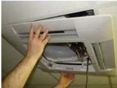
- Open Grill.
natural_image
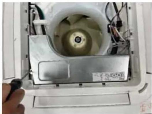
Close-up of hands installing or adjusting a white air vent grille on a wall (no text or symbols visible)- Remove the PCB cover by removing the two screws connecting the cover to the enclosure.
natural_image
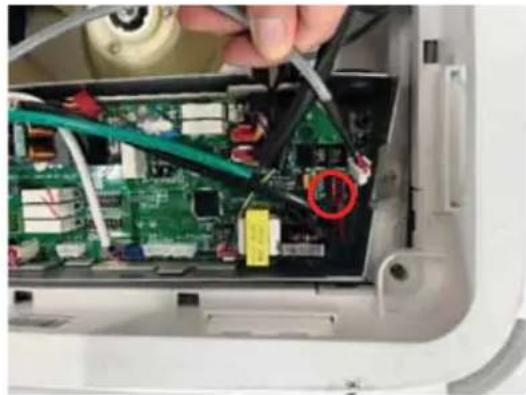
Interior view of a white appliance with visible internal components and wiring (no text or symbols)- Unplug the Refrigerant Leak Sensor from CN23 on PCB.
natural_image
Close-up of a hand using a tool to adjust or install electronic components on a green circuit board (no visible text or symbols)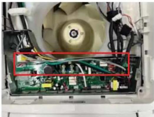
natural_image
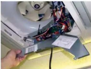
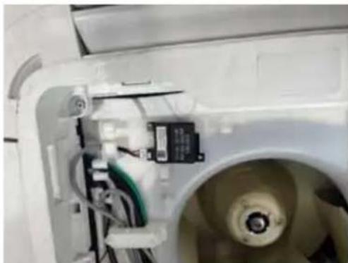
Interior view of an air conditioner fan with visible circuit board and wiring (no text or symbols)- Remove Refrigerant Leak Sensor from unit.
natural_image
Close-up of a white industrial machine with visible wiring and a small black component (no text or symbols)- Perform Steps 1 through 4 in reverse to connect new Refrigerant Leak Sensor.
GE Appliances Ductless HVAC Limited Warranty
GEAppliances.com. Please save your receipt showing the date of original purchase and the date of installation.
For the product models listed on Attachment 1 (the "Product"), this Standard Limited Warranty is provided to the Original Owner of the Product:
| For The Period Of: GE Appliances Will Replace: | |
| 1 Year Remote Controller WarrantyFrom the date of the original installation | If the Remote Controller proves to be defective due to improper workmanship and/or material for a period of one (1) year from the date of installation, GE Appliances, A Haier Company (“Haier”) will provide a new or refurbished controller, at Haier’s sole discretion. |
| 5 year Limited Parts WarrantyFrom the date of the original installation | If any parts should prove to be defective due to improper workmanship and/or material for a period of five (5) years from the date of installation, Haier will replace any defective parts without charge for the part. Parts used for replacement may be new or refurbished parts, determined at Haier’s sole discretion, and provided to your licensed HVAC technician installer. |
| 10 Year Registered Limited Parts WarrantyFrom the date of the original installation(ONLINE REGISTRATION REQUIRED at GEAppliances.com)MUST BE A RESIDENTIAL SINGLE-FAMILY HOME | If any of the parts should prove defective due to improper workmanship and/or material for a period of ten (10) years from the date of installation, Haier will replace any defective parts without charge for the part. The replacement part is warranted for the remainder of the original ten (10) year warranty period. Parts used for replacement may be new or refurbished parts, determined at Haier’s sole discretion, and provided to your licensed HVAC technician installer. This Registered Limited Parts Warranty requires online registration within sixty (60) days from the original date of installation or occupancy.NON-RESIDENTIAL/COMMERCIAL APPLICATIONS ARE NOT ELIGIBLE FOR THIS REGISTERED LIMITED PARTS WARRANTY. |
LABOR NOT COVERED:
These limited warranties DO NOT include labor or any other costs incurred for service, maintenance, repair, removing, replacing, installing, complying with local building or electrical codes, shipping or handling, replacement of the system, compressors or other parts.
EXCLUDED COMPONENTS:
The following components are not covered by this warranty: cabinets, cabinet pieces, air filters, driers, refrigerant, refrigerant line sets, belts, wiring, fuses, oil nozzles, unit accessories and any parts not affecting unit operation.
WHAT IS THE DATE OF PURCHASE:
The “Date of Purchase” is the date the Product is purchased by the Original Owner. The “Date of Installation” is the date that the original installation was completed and all Product start-up procedures were properly completed and verified by the installer’s invoice. If the installation date cannot be verified, then the Date of Installation will either be sixty (60) days after the manufacture date, as determined by the Product's serial number or thirty (30) days from the Date of Purchase. You should keep and be able to provide your original sales receipt from the installer as proof of the Date of Purchase and the Date of Installation. For new construction, the Date of Purchase will be the date of purchase of the residence by the Owner from the builder.
WHO IS COVERED:
Owner occupied: The “Original Owner” means the original owner (and his or her spouse) of a residential single family where the Product was originally installed.
Non-Owner occupied: The “Non-Owner occupied” is defined as a) single family or multi-family residential buildings that are not Owner Occupied, or b) light commercial applications, (such as office buildings, retail establishments, hotels/motels).
For Non-owner occupied, this limited warranty requires that the Product be installed and maintained annually by a licensed HVAC technician (proof of annual maintenance is required).
HOW CAN YOU GET SERVICE:
Contact your licensed HVAC technician installer. All installation and service must be performed by a licensed HVAC technician. Failure to use a licensed HVAC technician for installation of this Product voids all warranty on this Product.
GE Appliances Ductless HVAC Limited Warranty
WHAT GE APPLIANCES WILL NOT COVER:
- Improper service or installation.
- Damage in shipping.
- Defects other than manufacturing defects (i.e., other than workmanship or materials).
- Damage from misuse, abuse, accident, alteration, lack of proper care and/or regular maintenance.
- Damage resulting from floods, fires, wind, lightning, accidents or similar conditions.
- Product that was not installed or serviced by a licensed HVAC technician.
• Labor and related services for repair or installation of the Product. - A product purchased from an unauthorized online retailer.
- Damage as a result of subjecting Product to an atmosphere with corrosives or high levels of particulates (such as soot, aerosols, fumes, grease).
- Modification, change or alteration of the equipment, except as directed in writing by Haier.
- Use of contaminated or refrigerant not compatible with the unit.
- Operation with system components (indoor unit, outdoor unit, and refrigerant control devices) which are not an AHRI match or meet the specifications recommended by Haier.
• A Product sold and/or installed outside of the 50 United States,
the District of Columbia, or Canada.
- Batteries for the controller and other accessories provided with the Product for installation (e.g., plastic hose).
- Normal maintenance, such as cleaning of coils, cleaning filters, and lubrication.
- For Product installed in non-owner occupied applications, Product that has not been maintained annually by a licensed HVAC technician (proof required).
- Damage caused by a used or unapproved component or part by Haier (e.g., a used and/or unapproved condenser / air handler).
- Component or parts not provided by Haier.
- Product that has been moved from its original installation to a new residence or building.
- Accident, or neglect or unreasonable use or operation of the equipment including operation of electrical equipment at voltages other than the range specified on the unit nameplate (includes damages caused by brownouts).
- Damage to the product caused by accident, fire, floods or acts of God.
- Incidental or consequential damage caused by possible defects with this product.
LEGAL RIGHTS:
Some states and provinces do not allow warranty terms to be subject to registration. In those states and provinces, the 10 year Registered Limited Parts Warranty applies. In addition, if allowed by the law of the state or province where the Product is installed, the subsequent owners of the residence or building may have additional rights or longer warranty terms.
REGISTERED LIMITED PARTS WARRANTY COVERAGE REQUIREMENTS:
- The unit is a GE Appliances or a Haier branded unit.
- The unit is installed in a residential application.
- The unit is properly registered at GEAppliances.com within 60 days after the original date of installation or occupancy.
- The unit is part of a complete AHRI matched system and installed by a state certified or licensed contractor in accordance with the unit installation, operation, and maintenance instructions provided with the unit.
- Indoor and outdoor ductless units are covered only when they are branded GE Appliances and are purchased and installed as a system along with a qualifying unit. (Third party coils are not covered).
• Installation is in compliance with applicable laws, regulations, codes, and ordinances. - Unit was not ordered via the internet. Proof of purchase may be required.
EXCLUSION OF IMPLIED WARRANTIES:
EXCEPT TO THE EXTENT PROHIBITED BY APPLICABLE LAW, THIS LIMITED WARRANTY IS EXCLUSIVE AND GIVEN IN LIEU OF ALL OTHER WARRANTIES, EXPRESS OR IMPLIED, INCLUDING BUT NOT LIMITED TO ANY IMPLIED WARRANTY OF MERCHANTABILITY AND FITNESS FOR A PARTICULAR PURPOSE.
UNDER NO CIRCUMSTANCES SHALL HAIER BE LIABLE FOR ANY INDIRECT, INCIDENTAL, SPECIAL OR CONSEQUENTIAL DAMAGES INCLUDING, WITHOUT LIMITATION, LOST GOODWILL, LOST REVENUE OR PROFITS, WORK STOPPAGE, SYSTEM FAILURE, IMPAIRMENT OF OR DAMAGE TO OTHER EQUIPMENT OR GOODS, COST OF REMOVAL AND REINSTALLATION OF THE SYSTEM, LOSS OF USE, INJURY TO PERSONS OR PROPERTY ARISING OUT OF OR RELATED TO THE SYSTEM. HAIER'S TOTAL LIABILITY, IF ANY, UNDER THIS LIMITED WARRANTY SHALL NOT EXCEED THE INVOICE VALUE PAID BY THE CUSTOMER FOR THE SYSTEM WHICH IS THE SUBJECT OF A CLAIM OR DISPUTE.
SOME STATES DO NOT ALLOW THE EXCLUSION OR LIMITATION OF INCIDENTAL OR CONSEQUENTIAL DAMAGES, OR ALLOW DISCLAIMERS OF IMPLIED WARRANTIES, SO THE ABOVE LIMITATIONS OR EXCLUSIONS MAY NOT APPLY TO THE CUSTOMER. THIS LIMITED WARRANTY GIVES THE CUSTOMER SPECIFIC LEGAL RIGHTS. CUSTOMERS MAY ALSO HAVE OTHER RIGHTS THAT VARY FROM STATE TO STATE.
The remedy provided in this warranty is exclusive and is granted in lieu of all other remedies. This warranty does not cover incidental or consequential damages. Some states and provinces do not allow the exclusion of incidental or consequential damages, so this limitation may not apply to you. Some states and provinces do not allow limitations on how long an implied warranty lasts, so this limitation may not apply to you. This warranty gives you specific legal rights and you may also have other rights which vary by state and province. This warranty covers Products within the 50 United States, the District of Columbia and Canada.
This warranty is provided by:
GE Appliances, a Haier company Louisville, KY 40225
For US Customers: This limited warranty is extended to the original purchaser for products purchased for home use within the USA. In Alaska and Hawaii, the limited warranty does not include the costs of shipping units.
Some states do not allow the exclusion or limitation of incidental or consequential damages. This warranty gives you specific legal rights, and you may also have other rights which vary from state to state. To know what your legal rights are, consult your local or state consumer affairs office or your state's Attorney General.
Warrantor: GE Appliances, a Haier company Louisville, KY 40225
GE Appliances Ductless HVAC Limited Warranty
ATTACHMENT 1:
Product is defined as GE Appliances or Haier branded Ductless Split Units. The Product contains 2 sub-categories of goods: "Indoor and Outdoor Products" and "Selected Installation Products," which are further defined below: "Indoor and Outdoor Products" can further be identified by the following model number descriptions: 1Q^ , 2Q^ , 3Q^ , 4Q^ , 5Q^ , 1G^ , 2G^ , 3G^ , 4G^ , 5G^ , QS^ , QA^ , GA^ , GS^ , US^* .
AIR&WATER
SOLUTIONS
| Instructions d’Installation | Cassette compacte |

natural_image
Isometric line drawing of a ceiling fan installation with internal blades and mounting brackets (no text or symbols)CONSIGNES DE SÉCURITÉ IMPORTANTES
INSTRUCTIONS D'INSTALLATION
Étape 1 16
Étape 2....18
Étape 3....20
Étape 4 20
Étape 5 21
GARANTIELIMITÉE
23

GE Appliances, Air and Water
CONSIGNES DE SÉCURITÉ IMPORTANTES LISEZ TOUTES LES INSTRUCTIONS AVANT D'UTILISER L'APPAREIL
▲ AVERTISSEMENT
natural_image
Close-up of a metallic pipe fitting mounted on a dark metal frame, with no visible text or symbols.natural_image
Close-up of a white cylindrical object mounted on a metal frame, with wooden beams and a wooden shelf in the background (no visible text or symbols)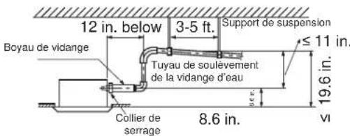
natural_image
Close-up of hands using a tool to adjust or install electronic components with visible wiring and connectors (no text or symbols)natural_image
Technical line drawing of a device with internal compartments and mounting brackets (no text or symbols)natural_image
Interior ceiling view of a building with exposed structural beams and central equipment (no visible text or symbols)natural_image
Close-up of hands using a tool on a wooden beam inside a ceiling structure (no text or symbols visible)natural_image
Close-up of ceiling grating with metal beams and wooden supports (no text or symbols visible)natural_image
Close-up of a mechanical component with intersecting lines and central hub (no visible text or symbols)natural_image
Close-up of hands using a tool to adjust or install a mechanical component (no visible text or symbols)natural_image
Close-up of hands using a mechanical clamp or tool to adjust a metal clamp (no text or symbols visible)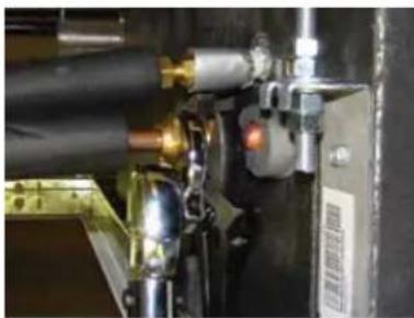
natural_image
Close-up of industrial machinery components with no visible text or symbolsnatural_image
Close-up of a white cylindrical object mounted on a wooden structure, with no visible text or symbols.natural_image
Close-up of a hand holding an electronic device with visible wiring and components, no text or symbols present.natural_image
Person installing or adjusting a white air conditioner cover with visible wiring and components (no text or symbols)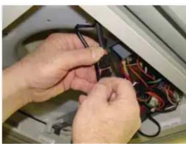
natural_image
Close-up of hands installing or adjusting a black electrical component with wires (no visible text or symbols)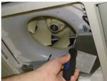
natural_image
Hand holding a handheld device next to a white appliance with a circular vent (no visible text or symbols)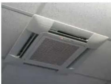
natural_image
Close-up of a white ventilation grille with mesh pattern (no text or symbols visible)natural_image
Close-up of hands installing or adjusting a white air vent grille on a wall (no text or symbols visible)natural_image
Interior view of a refrigerator showing the open lid and internal fan blades (no visible text or symbols)natural_image
Close-up of a hand using a tool to adjust or install a green circuit board with visible wiring and components (no text or symbols)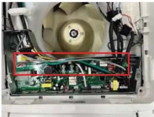
natural_image
Interior view of an open air fan with visible circuit board and wiring (no text or symbols)natural_image
Close-up of a white industrial machine interior with visible wiring and components (no text or symbols)CE QUE GE APPLIANCES NE COUVRIRA PAS
GE Appliances, a Haier company Louisville, KY 40225
Warrantor: GE Appliances, a Haier company Louisville, KY 40225
natural_image
Isometric line drawing of a ceiling fan installation with concentric square patterns (no text or symbols)GEAppliancesAirandWater.com/Warranty

GE Appliances, Air and Water
natural_image
Close-up of a metallic pipe fitting mounted on a concrete wall, with no visible text or symbols.natural_image
Close-up of a white cylindrical object mounted on a metal frame, with wooden beams and no visible text or symbols.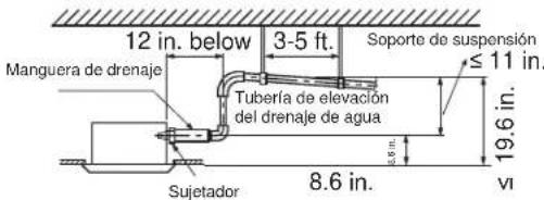
natural_image
Close-up of hands installing or adjusting cable wiring on an electronic device (no visible text or symbols)natural_image
Technical line drawing of a mechanical device with internal components and housing (no text or symbols)natural_image
Interior ceiling view of a building with exposed structural beams and internal components (no visible text or symbols)natural_image
Close-up of hands installing or adjusting a wooden beam with a tool, against a wooden ceiling (no text or symbols visible)natural_image
Close-up of ceiling grating with metal beams and insulation material (no text or symbols visible)natural_image
Close-up of a ceiling-mounted fixture with metal components and wiring (no visible text or symbols)natural_image
Close-up of hands using a tool to adjust or install a mechanical component (no visible text or symbols)natural_image
Two-panel image showing hands operating a mechanical clamp and a close-up of a mechanical assembly with brass fittings (no visible text or symbols)natural_image
Close-up of a white cylindrical object mounted on a dark metal frame, with wooden beams and no visible text or symbols.natural_image
Close-up of a hand holding a plastic electronic device with exposed internal wiring and components (no visible text or symbols)natural_image
Person installing or adjusting a white air conditioner unit with visible wiring and components (no text or symbols)
natural_image
Close-up of hands installing or adjusting cable wiring on a device (no visible text or symbols)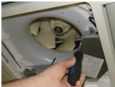
natural_image
Hand holding a handheld device next to a fan-shaped vent (no visible text or symbols)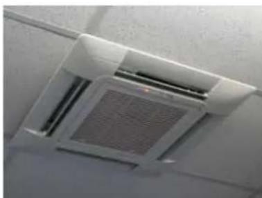
natural_image
Close-up of a white ceiling HVAC grille with a mesh grille and ventilation slots (no text or symbols visible)Paso 5 – Control Final
Control Final
natural_image
Person installing or adjusting a white air conditioner cover on a wall (no text or symbols visible)natural_image
Interior view of a refrigerator showing the interior casing with visible wiring and components, no text or symbols present.natural_image
Close-up of a hand using a tool to inspect internal components of an electronic device (no visible text or symbols)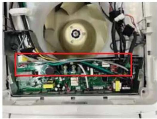
natural_image
Interior view of an electric fan with visible circuit board and wiring (no text or symbols)natural_image
Close-up of a white industrial machine interior with visible wiring and components (no text or symbols)GE Appliances, a Haier company
Louisville, KY 40225
Warrantor: GE Appliances, a Haier company
Louisville, KY 40225


- Installation Instructions Compact Cassette
- RECORD KEEPING
- IMPORTANT SAFETY INFORMATION READ ALL INSTRUCTIONS BEFORE USING THE APPLIANCE
- WARNING
- ATTENTION
- READ AND SAVE THESE INSTRUCTIONS
- BEFORE YOU BEGIN
- Safety Awareness
- Unpacking Inspection
- Inspection on Installation Environment
- Safety Principles of Installation
- CAUTION
- Requirements for Operation, Service and Installation of Appliances Using Flammable Refrigerants
- General
- General (cont.)
- Qualification of workers
- Examples for such working procedures are:
- Information on servicing
- Information on servicing (cont.)
- Repairs to sealed components, intrinsically safe components
- Cabling
- Detection of flammable refrigerants
- NOTE: Examples of leak detection fluids are:
- Removal and evacuation
- Charging procedures
- Decommissioning
- Labeling
- Recovery
- CONSIGNES DE SÉCURITÉ IMPORTANTES LISEZ TOUTES LES INSTRUCTIONS AVANT D'UTILISER L'APPAREIL
- ▲AVERTISSEMENT
- Required Tools for Installation
- Supplied with Unit
- Supplied by Installer
- Cassette Product Information
- Fresh Air Intake Option
- Condensate Handling
- Electrical Power
- Air Delivery Clearances
- Service and Maintenance Clearances
- MINIMUM CLEARANCES (Appearance may vary)
- Step 1 - Preparation
- Before installing the indoor unit, determine if a refrigerant leak sensor is required.
- If leak sensor is not needed, make sure to flip dip switch 1-5 to ON.
- Step 1 - Preparation (cont)
- Install the Leak Sensor
- Procedure for selecting the location:
- NOTES:
- Threaded Rod Mounting Information:
- Step 2 - Installation of the Cassette Unit
- One Inch Recess:
- Step 2 - Installation of the Cassette Unit (Cont.)
- Step 3 - Electrical Connections
- Electrical connections indoor and outdoor units
- Step 4 - Leak Testing, Evacuation and Wifi
- Wifi Pairing
- After downloading the App:
- Software Notice
- Step 5 - Final Check
- Final Check
- Start Up Checklist
- Verify Refrigerant Leak Sensor Function
- Explaining Operation to the End User
- Refrigerant Leak Sensor Replacement Instructions
- GE Appliances Ductless HVAC Limited Warranty
- LABOR NOT COVERED:
- EXCLUDED COMPONENTS:
- WHAT IS THE DATE OF PURCHASE:
- WHO IS COVERED:
- HOW CAN YOU GET SERVICE:
- WHAT GE APPLIANCES WILL NOT COVER:
- LEGAL RIGHTS:
- REGISTERED LIMITED PARTS WARRANTY COVERAGE REQUIREMENTS:
- EXCLUSION OF IMPLIED WARRANTIES:
- GE Appliances, a Haier company Louisville, KY 40225
- ATTACHMENT 1:
- AIR&WATER
- SOLUTIONS
- CONSIGNES DE SÉCURITÉ IMPORTANTES
- INSTRUCTIONS D'INSTALLATION
- GARANTIELIMITÉE
- ▲ AVERTISSEMENT
- CE QUE GE APPLIANCES NE COUVRIRA PAS
- Paso 5 – Control Final
- Control Final
Brand : HAIER
Model : Caliber US12CB2BEA
Category : Air Conditioning