
RB900 - Extraction fan FABER - Free user manual and instructions
Find the device manual for free RB900 FABER in PDF.

| Product Type | Exhaust Fan |
| Brand | Faber |
| Model | RB900 |
| Usage | Domestic |
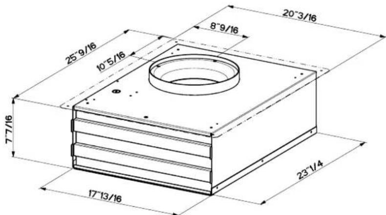
| Dimensions (L x H x D) | 20-3/16 x 25-9/16 x 17-13/16 in |
| Duct Diameter | 10 in (25.4 cm) |
| Maximum Duct Length | 55 ft (16.8 m) |
| Electrical Supply | 120 V, 60 Hz, AC, 15 A |
| Conductor Type | Copper only |
| Grounding | Required (green screw) |
| Compatibility | Hood INCA PRO PLUS |
| Control Type | Compatible with integrated circuit speed controls |
| Duct Material | Metal only |
| Motor Maintenance | Lifetime lubricated bearings, do not lubricate |
| Cleaning | Disconnect, clean with vacuum, do not damage turbine |
| Installation | By a qualified professional |
| Exhaust | Must vent to outside, not into attic or enclosed space |
| Warranty | 1 year (parts and labor) |
| Wear items (not covered) | Filters, bulbs |
| Weight | Approximately 14 kg (estimated) |
Frequently Asked Questions - RB900 FABER
User questions about RB900 FABER
0 question about this device. Answer the ones you know or ask your own.
Ask a new question about this device
Download the instructions for your Extraction fan in PDF format for free! Find your manual RB900 - FABER and take your electronic device back in hand. On this page are published all the documents necessary for the use of your device. RB900 by FABER.
USER MANUAL RB900 FABER
READ AND SAVE THESE INSTRUCTIONS
The installer must leave these instructions with the homeowner. The homeowner must keep these instructions for future reference and for local electrical inspectors' use.

WARNING
You can be killed or seriously injured if you don't follow instructions.
TO REDUCE THE RISK OF FIRE, ELECTRIC SHOCK, OR INJURY TO PERSONS, OBSERVE THE FOLLOWING:
Installation work and electrical wiring must be done by qualified person(s) in accordance with all applicable Codes and Standards, including Fire Rated Construction. Sufficient air is needed for proper combustion and exhausting of gases through the flue (chimney) of fuel burning equipment to prevent back drafting. Follow the heating equipment manufacturer's guideline and safety standards such as those published by the National Fire Protection Association (NFPA), and the American Society of Heating Refrigeration and Air Conditioning Engineers (ASHRAE), and the local code authorities. When cutting or drilling into wall or ceiling, do not damage electrical wiring and other hidden utilities. Ducted fans must always be vented to the outdoors.
Use this unit only in the manner intended by the manufacturer. If you have any questions, contact the manufacturer.
Before servicing or cleaning unit, switch power off at service panel and lock the service disconnecting means to prevent power from being switched on accidentally. When the service disconnecting means cannot be locked, securely fasten a prominent warning device, such as a tag, to the service panel.
WARNING - TO REDUCE THE RISK OF SHOCK: This fan must be installed with an isolating wall control/ switch.
CAUTION: For General Ventilating Use Only. Do Not Use To Exhaust Hazardous or Explosive Materials and Vapors.
To reduce the risk of fire, use only metal ductwork.
This unit must be grounded.
This unit is suitable for use with solid-state speed controls.
For Residential use ONLY
Note: please refer to the Inca Pro Plus installation instructions for connecting the remote blower to the rangehood
CAUTION – To reduce risk of fire and to properly exhaust air, be sure to duct air outside – Do not vent exhaust air into spaces within walls or ceilings or into attics, crawl spaces, or garages”
Important
Observe all governing codes and ordinances. Proper installation is your responsibility. Make sure you have everything necessary for correct installation. It is the responsibility of the installer to comply with the clearances specified.
To avoid damage to motor bearings and impellers, keep drywall spray, construction dust, etc. away from the remote blower.
Before installing remote blower, read the installation instructions for the vent system that will be used in conjunction with this remote blower.
Care of your remote blower
Disconnect power supply and lock out service panel before cleaning or
servicing. To clean, remove cover and vacuum blower and housing, being careful not to damage blower wheel. The motor is permanently lubricated. Do not oil or disassemble.
Electrical requirements
Important: Observe all governing codes and ordinances. It is the customer's responsibility:
- To contact a qualified electrical installer.
- To assure that the electrical installation is adequate and in conformance with:
National Electrical Code, ANSI/NFPA 70 — latest edition*, or CSA
Standards C22.1-94, Canadian Electrical Code, Part 1 and C22.2
No.0-M91 - latest edition** and all local codes and ordinances.
If codes permit and a separate ground wire is used, it is recommended that a qualified electrician determine that the ground path is adequate. Do not ground to a gas pipe. Check with a qualified electrician if you are not sure remote blower is properly grounded. Do not have a fuse in the neutral or ground circuit.
A 120-volt, 60-Hz, AC-only supply wired for 15 amp service is required.
The blower motor must be connected with copper wire only.
The remote blower must be connected to the rangehood wiring as described in the rangehood instructions for connecting the remote blower motor wiring. Flexible armored or nonmetallic cable must be used. A U.L./CSA-listed strain relief must be provided at each end of the power supply cable. Wire sizes must conform to the requirements of the National Electrical Code ANSI/NFPA 70 — latest edition* or Canadian Electrical Code, C22.1 and C22.2 No. 113-M1984 (or latest edition),** and all local codes and ordinances. 14 gauge wire (minimum) is recommended.
Copies of standards listed may be obtained from:
* National Fire Protection Association
One Batterymarch Park
Quincy, Massachusetts 02269
** CSA International
8501 East Pleasant Valley Road
Cleveland, Ohio 44131-5575
Venting requirements
Determine which ducting method is best for your application. Duct system can extend either through the wall or the roof. Locate the remote blower so that the length of the duct system and the number of elbows is kept to a minimum to provide efficient performance. Where possible, remote blower should be centered between wall studs or roof rafters. The size of the duct system should be uniform. Do not install two elbows together.
Use duct tape to seal all joints in the duct system. Use caulking to seal remote wall or floor opening around the cap. Flexible duct is not recommended. It creates back pressure/air turbulence and greatly reduces performance. Make sure there is proper clearance within the wall or floor for exhaust duct before making cutouts. Avoid pipes, wires, or other duct systems that may be running through the wall. Do not cut a joist or stud unless absolutely necessary. If a joist or stud must be cut, then a supporting frame must be constructed.
natural_image
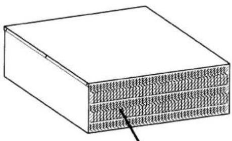
Simple line drawing of a rectangular block with internal hatched texture and a small arrow pointing to its bottom section (no text or symbols)Install this side of the fan facing an unoccupied space.
Maximum length of ductwork
55 feet for 10" round ductwork - count 90° elbows as 5 feet and 45° elbows as 3 feet.
Duct length is given as a general reference only. For a longer duct run, or smaller duct system, contact a qualified and trained duct installer. Check with local codes for makeup air requirements, if any. It is recommended that you use round duct instead of rectangular duct, especially if elbows are required. If rectangular duct is required, if should be transitioned to 10" (25.4 cm) round duct as soon as possible.
For best performance, use no more than three 90 elbows. If more than one elbow is used, make sure that there is a minimum of 24 inches of straight duct between any two elbows. Do not install two elbows together.
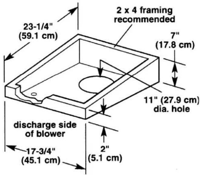
REMOTE BLOWER CONTENTS
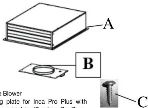
A) Remote Blower
B) Ducting plate for Inca Pro Plus with wiring box and cables (See Inca Pro Plus instructions for more information)
C) Installation Screws for Mounting Plate
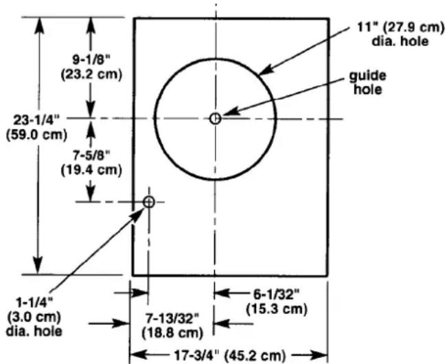
Dimensional diagram
MAKE SURE THAT THE DISCHARGE END OF THE REMOTE BLOWER FACES AWAY FROM THE DIRECTION OF PREVAILING WINDS.

WARNING
You can be killed or seriously injured if you don't follow instructions.
Excessive Weight Hazard
Use two or more people to move and install remote blower.
Failure to do so can result in back or other injury.
Begin the installation
- Discard any cardboard packaging from the blower wheel.
- Remove wiring box cover and screws.
- Attach an appropriate U.L./CSA-listed strain relief in the knockout.
Note: For most installations, it is recommended that the strain relief be installed so that it can be tightened from inside the remote blower housing.
- Reattach the wiring box cover loosely. It will be removed again later.
Wall installations
- Choose a location on an outside wall where no wall studs, wires, pipes, etc. run through the opening area. A minimum distance of 24" (61 cm) from remote blower to ground may be required depending on local code. Make sure to leave room for anticipated snowfall in your region.
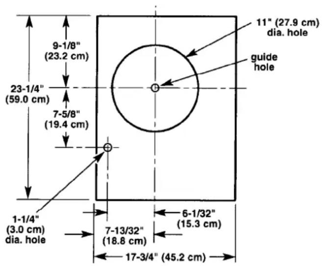
- Drill the guide hole in the center of the 11" (27.9 cm) diameter opening area.
- Mark a 27-1/2" x 34" (69.9 x 86.4 cm) rectangle on wall as indicated in FIGURE 1.
- Cut a rectangular hole in the siding only. Do not cut sheathing. Nail down all siding ends.
- Mark an 11" (27.9 cm) diameter circle around guide hole as indicated in FIGURE 1. Mark center of the 1-1/4" (or 3.0 cm) diameter hole for electrical wiring as indicated in FIGURE 1.
- Cut 11" (27.9 cm) diameter hole in sheathing. Drill the 1-1/4" (or 3.0 cm) diameter electrical wiring hole.
- Run a large bead of caulk on the back side of the housing along the outer edge.
- Center the remote blower ring in the 11" (27.9 cm) diameter hole, making sure that the 1-1/4" (or 3.0 cm) diameter electrical wiring hole lines up with the hole in the wiring box.
- Attach the remote blower to wall using screws appropriate for your installation. All four holes in the back panel must be filled to prevent moisture that may get inside the remote blower housing from leaking into the home.
- Seal all around the mounting screw heads with caulk.
- Go to "Make the duct & electrical connections", Page 4.
Roof installations FOR FLAT ROOF INSTALLATIONS SEE NEXT PAGE
- Choose location on rear slope of roof that minimizes vent run. Avoid obstacles such as TV leads, electric lines, etc. If remote blower top is level with roof peak, it will not be seen from street. Remember this location as you work from inside the attic.
- Mark a point half-way between the rafters and drill a guide hole at this point.
- From the outside, using the guide hole as a starting point, mark the rectangular cut-out as indicated in FIGURE 2. Remove ONLY the shingles in THIS AREA.
- Mark an 11" (27.9 cm) diameter circle around guide hole as indicated in FIGURE 2. Mark center of the 1-1/4" (or 3.0 cm) diameter hole for the electrical wiring as indicated in FIGURE 2.
- Cut out the roof boards along the 11" (27.9 cm) diameter circle. Drill the 1-1/4" (or 3.0 cm) diameter electrical wiring hole.
- Remove roofing nails from the upper two-thirds of the shingles to allow the back flashing sheet on the remote blower housing to fit under them.
- Center the remote blower ring in the 11" (27.9 cm) diameter hole, making sure that the 1-1/4" (or 3.0 cm) diameter electrical wiring hole lines up with the hole in the wiring box.
- Attach the remote blower to roof or frame using screws appropriate for your installation. All four holes in the back panel must be filled to prevent moisture that may get inside the remote blower housing from leaking into the home.
- Seal all the shingles around the remote blower housing, flashing sheet, and mounting screw heads or frame with roofing cement. Top and side flanges of the back plate may be covered with trim. It is recommended that electrical connection be made and checked first. Do not block the vent grill opening at the bottom of the trim. Doing so will decrease blower performance.
Figure 1- Wall installations Figure 2 - Roof installations
Version 11/10 - Page 3
Figure 3 - Flat roof installations
Flat roof installations
- Locate the 11" (27.9 cm) dia. hole between rafters.
- Build a sloping base that will mount the remote blower at a minimum pitch of 2-1/2" (6.4 cm).
- Weatherproof the base as required.
- Locate the base so that the remote blower's vent aligns with the 11" (27.9 cm) dia. hole and the blower sits evenly on the base with no gaps. Note: Make sure that the discharge end of the remote blower faces away from the direction of prevailing winds.
- Use dimensions from either FIGURE 1 or 2 to locate the 1-1/4" (3.0 cm) dia. wiring hole. CONTINUE WITH POINT 6 UNDER ROOF INSTALLATIONS ON PAGE 3.
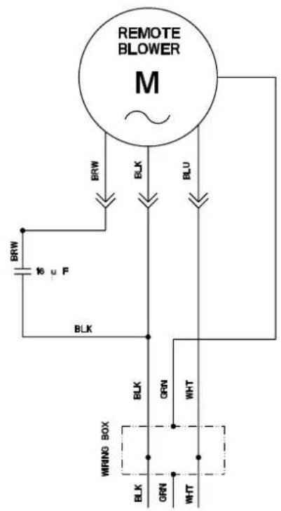
wiring diagram

WARNING
You can be killed or seriously injured if you don't follow instructions.
TO REDUCE THE RISK OF FIRE, ELECTRIC SHOCK, OR INJURY TO PERSONS, OBSERVE THE FOLLOWING:
- Disconnect power before making electrical connection.
- Connect the ground wire to green ground screw in wiring box.
Failure to do so can result in death or electrical shock.
Make the duct & electrical connections
- Remove the cover from the remote blower. Then remove the wiring box cover.
- Pull electrical wiring through the hole in the blower base and secure it according to local codes.
- Make the electrical connections. Connect the white and black wires of the power supply cable wire to the white and black wires in the wiring box with twist-on connector. Connect the green power supply ground wire to the green ground screw.
Figure 4 - Electrical connections
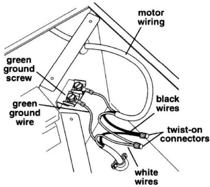
- Replace the wiring box cover and screws taking care not to pinch the wiring under the wiring box cover.
- Turn on power (See Installation Instructions that came with your vent hood system). Check operation of blower and make sure damper is opening freely.
- Reinstall remote blower housing.
Warranty & Service
All Faber products are warranted against any defect in materials or workmanship for the original purchaser for a period of 1 year from the date of original purchase. This warranty covers labor and replacement parts. The warranty does not cover consumable parts such as filters and light bulbs. This warranty does not apply if this product has been subjected to faulty installation, misuse, or neglect. This warranty excludes any consequential expense or damage resulting from any use or malfunction of the product. All implied warranties are limited to the duration of this warranty.
To obtain warranty service, contact the dealer from whom you purchased the rangehood, or the local Faber distributor. If you cannot identify a local Faber distributor, contact us at (508) 358-5353 for the name of a distributor in your area.
FABER
RB900
8501 East Pleasant Valley Rd.
Cleveland, Ohio 44131-5575
natural_image
Simple line drawing of a rectangular block with internal hatched texture and a small arrow pointing to one side (no text or symbols)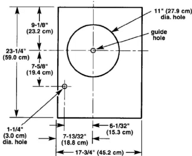
Version 11/10 - Page 7