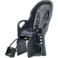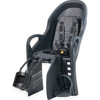
Dash FM - Child bike seat Burley - Free user manual and instructions
Find the device manual for free Dash FM Burley in PDF.


User questions about Dash FM Burley
0 question about this device. Answer the ones you know or ask your own.
Ask a new question about this device
Download the instructions for your Child bike seat in PDF format for free! Find your manual Dash FM - Burley and take your electronic device back in hand. On this page are published all the documents necessary for the use of your device. Dash FM by Burley.
USER MANUAL Dash FM Burley
natural_image
Silhouette of a bicycle with front wheel, rear wheel, and side seat (no text or symbols)BICYCLE SEAT MANUAL
DASH ^® FM & DASH ^® X FM
IMPORTANT: READ CAREFULLY AND KEEP FOR FUTURE REFERENCE
IMPORTANT : LISEZ ATTENTIVEMENT CE DOCUMENT ET GARDEZ-LE POUR RÉFÉRENCE FUTURE
IMPORTANTE: LEA ATENTAMENTE ESTE MANUAL Y CONSÉRVELO PARA FUTURAS CONSULTAS
CAUTION 4
Compatibility 6
Burley Bicycle Seat Guide 7
Attaching the Mounting Rails to Your Bicycle Seat 8
Attaching the Frame Mounting System to Your Bicycle 12
Attaching the Bicycle Seat to Your Bicycle 13
Checking the Position of the Bicycle Seat 14
Securing the Safety Strap 16
Securing the Child 17
Adjusting the Footrests 18
Adjusting the Harness 19
Adjusting the Recline of the Seat (Dash X FM only) 20
Removing the Bicycle Seat From Your Bicycle 21
Removing the Frame Mounting Assembly 21
Removing the Mounting Rails 21
Before You Ride 22
Connect With Burley 22
Product Identification 22
Maintaining Your Burley 22
Maximum Capacities 22
Burley Limited Warranty 23
Important
Before using your Bicycle Seat, please familiarize yourself with this Burley manual. For questions and additional information, please contact your authorized Burley dealer or visit www.burley.com.

- WARNING! Failure to comply with the manufacturer's instructions can lead to serious injury or death of the passenger/rider.
-
WARNING: Do not attach additional luggage to the child carrier.
-
Attaching additional luggage or accessories may exceed the load limit of the Bicycle Seat, and may lessen the stability (see page 22 for load limits).
- It is recommended to carry any additional luggage or accessories at the opposite end of the bicycle from the Bicycle Seat (i.e. use a front luggage carrier when using a rear Bicycle Seat).
- WARNING: The cycle may behave differently with a child in the seat.
- The load of a Child Bicycle Seat may lessen the stability and alter the riding characteristics of the bicycle, particularly regarding steering and braking.
- Presence of a Child Bicycle Seat on a bicycle may require alteration of the method used by the rider to mount or dismount the bicycle. Care must be taken whenever the rider gets on or off the bicycle.
-
Before each ride, ensure the mounted Bicycle Seat does not interfere with braking, pedaling, or steering of the bicycle.
-
WARNING: Never leave the bicycle parked with a child in the Bicycle Seat unattended.
- Never leave the child in a Bicycle Seat with the bicycle supported only by a kickstand.
- WARNING: Do not modify the Bicycle Seat.
- WARNING: Do not use the Bicycle Seat if any part is broken.
- WARNING: The Safety Strap must always be fastened to the bicycle frame before use (see Page 16)
- The bicycle to which the Bicycle Seat is attached must be in good working order, of a type appropriate for the additional load, and of proper size and adjustment for the rider.
- Check the bicycle user manual, or contact the bicycle manufacturer/supplier to obtain applicable information, to ensure the bicycle is appropriate for use with a Child Bicycle Seat.
- Tighten fasteners to specified torque values and check frequently. If you do not have a torque wrench, please visit a bicycle retailer to ensure proper installation.
- Ensure that any exposed rear saddle springs are covered with a suitable spring guard.
- Ensure that there are no sharp objects within reach of the child, e.g. frayed cables.
- The red reflector that came attached to the Bicycle Seat, which complies with CPSC regulations, must be visible on the rear of the Bicycle Seat whether the Bicycle Seat is on the bicycle or not.
- Always remove the Bicycle Seat from the bicycle when the bicycle is being transported on/outside a motor vehicle. This is necessary because the force of the high wind and air turbulence on the carrier may degrade or damage the Bicycle Seat (particularly the bicycle attachment mechanism) to the point that it will not perform reliably, which could result in an accident or serious injury.
- Dash X FM: Do not remove the Recline Mechanism from the Bicycle Seat.
- The rider of the bicycle must be a minimum of 16 years old with good bicycle riding and handling skills.
CAUTION
- Always check whether there are any laws specific to the carrying of children in Bicycle Seats attached to bicycles that apply in the country in which the Bicycle Seat is used.
- Do not carry a child who is too young to sit comfortably, safely, and independently in the Bicycle Seat. Carry only children that are able to sit unaided for a longer period of time, at least as long as the intended cycle journey (A pediatrician should be consulted before any child younger than one year is carried).
- Do not attempt to carry more than one child in the Bicycle Seat.
- Ensure initially, and check from time to time, that the child's weight does not exceed the load limit of the Bicycle Seat (see page 22 for load limits).
- Ensure that it is not possible for any part of the child's body, clothing, shoelaces, or toys to come into contact with any moving part of the Bicycle Seat or bicycle and re-check as the child grows. Particular dangers include entrapment of feet in the wheel and of fingers in brake mechanisms and sprung saddles.
- Always attach the 5-point harness snugly around the child, ensuring they are restrained in the Bicycle Seat.
- Ensure that the restraint system is not loose or able to become trapped in any moving parts, particularly the wheels. When no child is being carried, fasten the retention system buckles so that the straps do not hang loosely.
- Ensure the rider and child are wearing suitable bicycle helmets that meet applicable safety standards.
- Children in the Bicycle Seat need to be more warmly clothed than riders of bicycles and should be protected from rain.
- Check any excessive temperature (e.g. due to direct exposure to sun) of the Bicycle Seat before placing the child in it.
- Never ride in inclement or hazardous conditions.
- Never ride the bicycle at night without adequate lighting.
- It is not recommended to use the Bicycle Seat when riding your bicycle on off-road surfaces.
- Ensure that the free end of the Safety Strap cannot contact the wheel of the bicycle. If needed, excess webbing material can be wrapped around the Seat Tube multiple times before securing the buckle.
- Recommended maximum speed limits:
- 15 mph (24 km/h) on smooth, straight roads
- 5 mph (8 km/h) when turning or on uneven roads
Compatibility
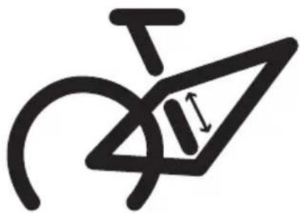
- This Bicycle Seat must only be mounted to bicycles with the following frame characteristics:
- Tube Shape: Round or Oval
- Tubing Diameter: 1.10 - 1.57 in (28 - 40 mm)
- Minimum Seat Tube Length: 4.10 in (105 mm)
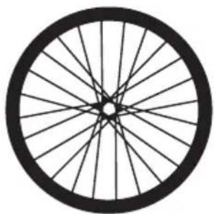
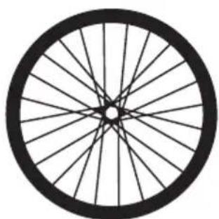
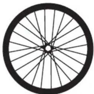
- This Bicycle Seat must only be mounted to bicycles with wheel diameters of either: 26", 650B/27.5", 700C, 29".
• This Bicycle Seat must NOT be mounted to:
- Full Suspension Bicycles
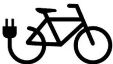
- Motorized Vehicles (E-Bikes OK)
- Bicycles with triangular or square-shaped tubes
- Bicycles with carbon fiber frames
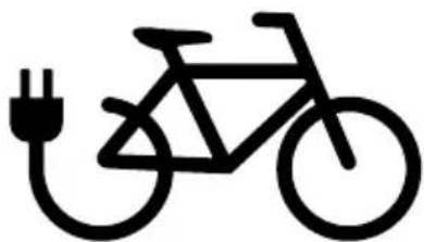
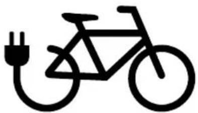
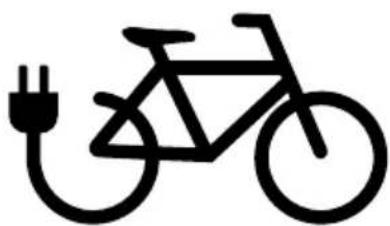
- This Bicycle Seat is compatible with E-Bikes, as long as the requirements listed above are met.
• Always consult with the bicycle manufacturer to ensure it is compatible with Bicycle Seats.
natural_image
Abstract black line drawing with curved and angular shapes, no text or symbols presentI 4.1 in | I105 mm ∅ 1.10"-1.57" | ∅ 28-40 mm
natural_image
Simple line drawing of a bicycle wheel with spokes (no text or symbols)26", 650B/27.5" 700C, 29"
natural_image
Simple line drawing of a bicycle with an electric plug (no text or symbols)E-Bike Compatible
For additional resources, please view our Dash FM/X FM Fit Guide on burley.com
| 6 | ENG | BURLEY | CHILD BIKE SEAT |
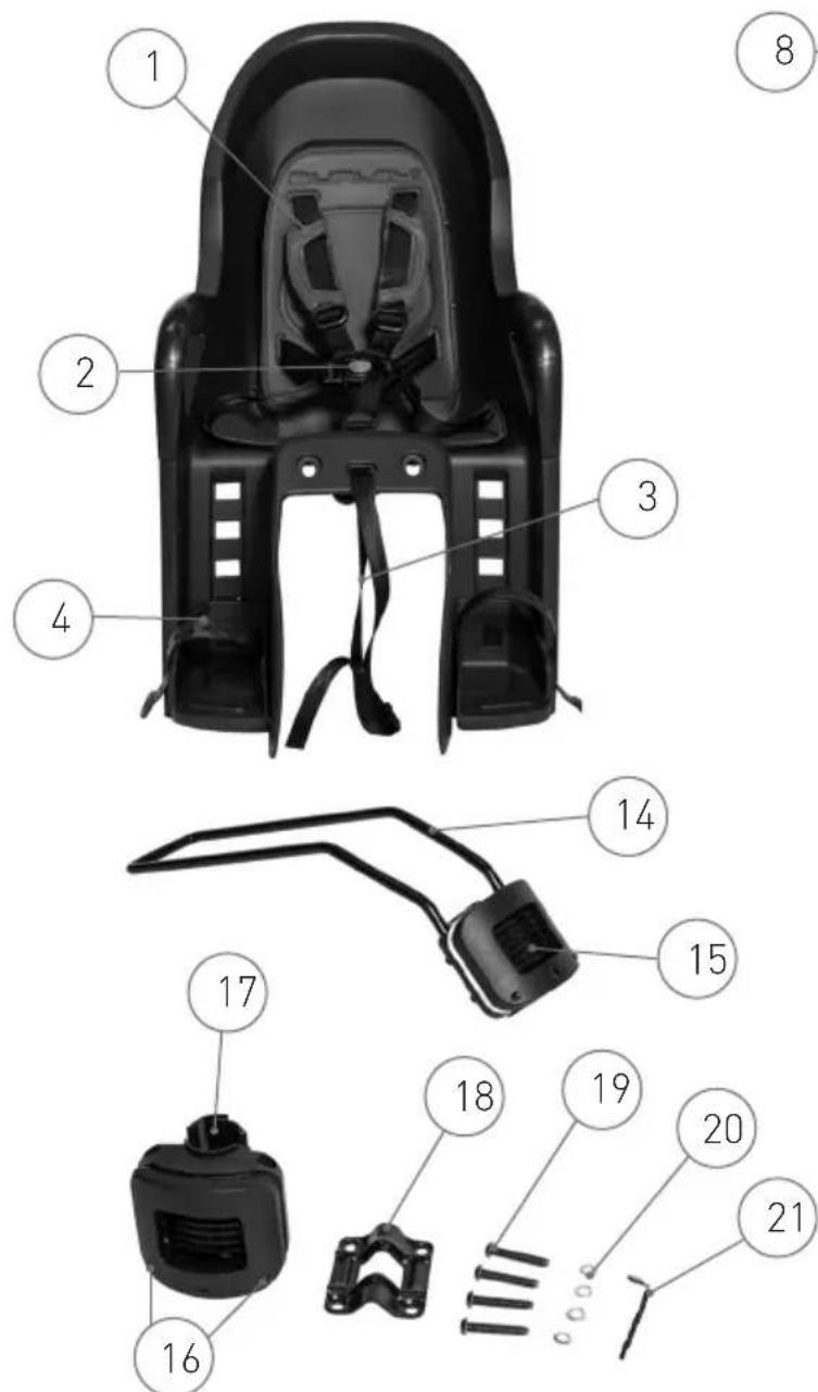
Burley Bicycle Seat Guide:
- Harness
- 5-Point Buckle
- Safety Strap
- Footrest
- Rear Storage Compartment
- Product Identification
- Harness Connector
- Center of Gravity Indicator
- Serial Number Label
- Frame Mounting System
- Mounting Knob
-
Locking Ring
-
Base Plate
- Mounting Rails
- Mounting Block
- Security Indicators
- Frame Protector
- Mounting Plate
- Screws
- Lock Washers
- Hex Wrench
22x. Recline Mechanism
23x. Safety Lever
24x. Recline Lever
text_image
Exploded view diagram of a device with numbered parts for identification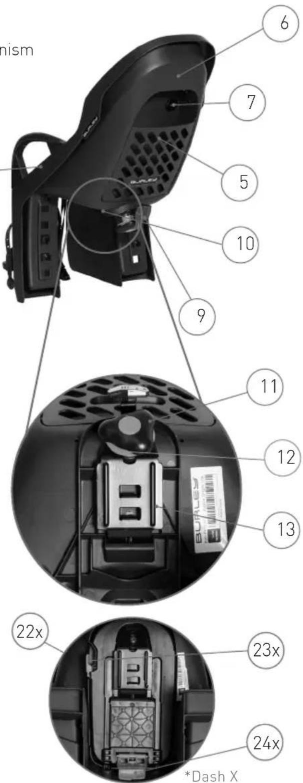
text_image
nism 6 7 5 10 9 11 12 13 22x 23x 24x *Dash XAttaching the Mounting Rails to Your Bicycle Seat
DASH FM
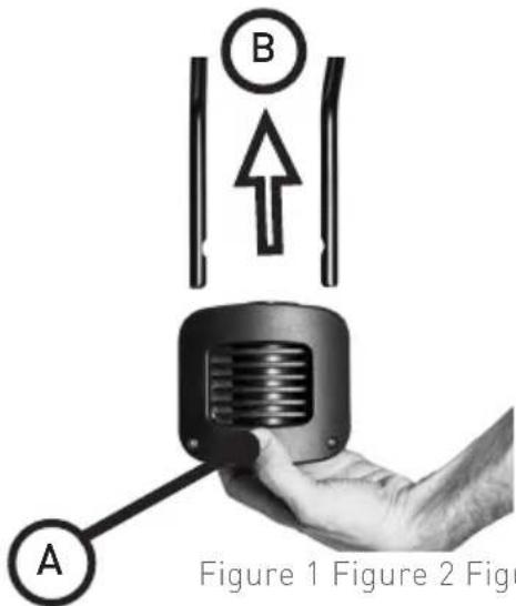
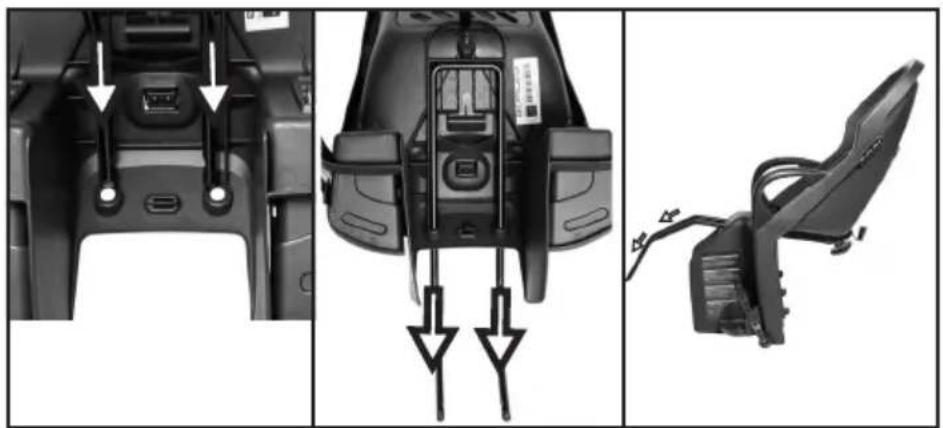
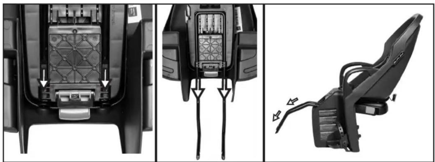
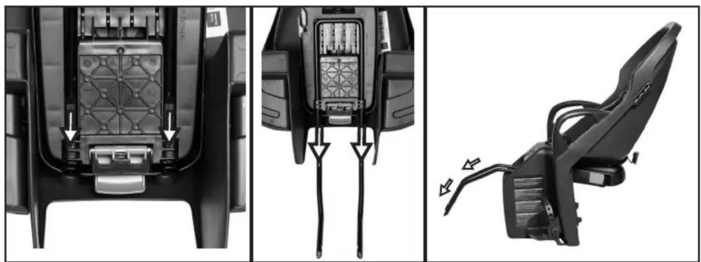
- Remove the Mounting Rails from the Mounting Block by depressing the front face of the Mounting Block [Figure 1a] and simultaneously pull the Mounting Rails out of the Mounting Block [Figure 1b].
NOTE: Pull both Mounting Rails from Mounting Block at the same time for smooth removal.
-
Remove the Mounting Knob by lifting the Locking Ring up away from the Bicycle Seat [Figure 2a], and rotating the Mounting Knob counter-clockwise until detached [Figure 2b].
-
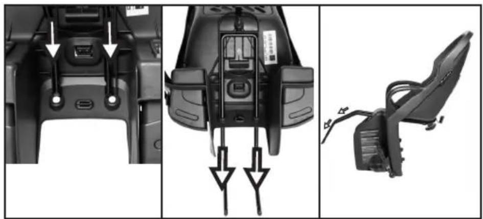
Flip the Base Plate away from the Bicycle Seat and remove it from the slots on the underside of the Bicycle Seat [Figure 3].
-
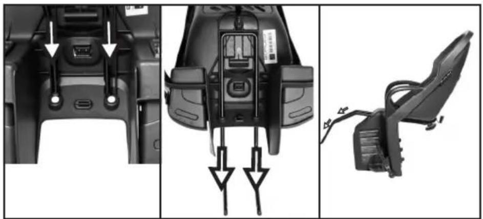
Pass the Mounting Rails through the 2 holes between the legs of the Bicycle Seat [Figure 4].
NOTE: The orientation of the Mounting Rails should be such that they are bending downwards [Figure 4].
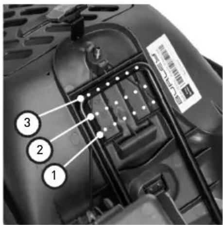
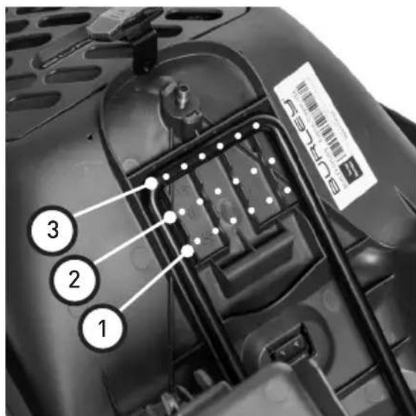
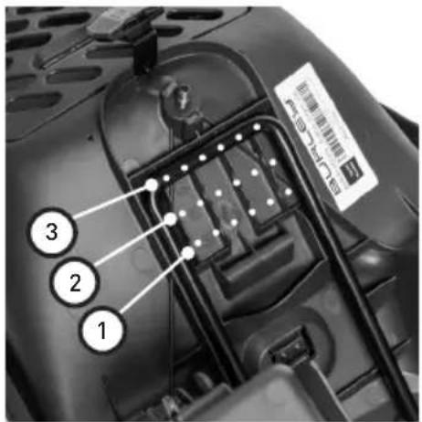
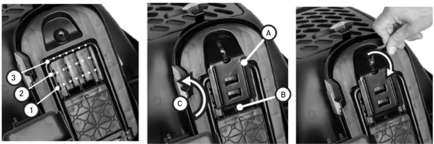
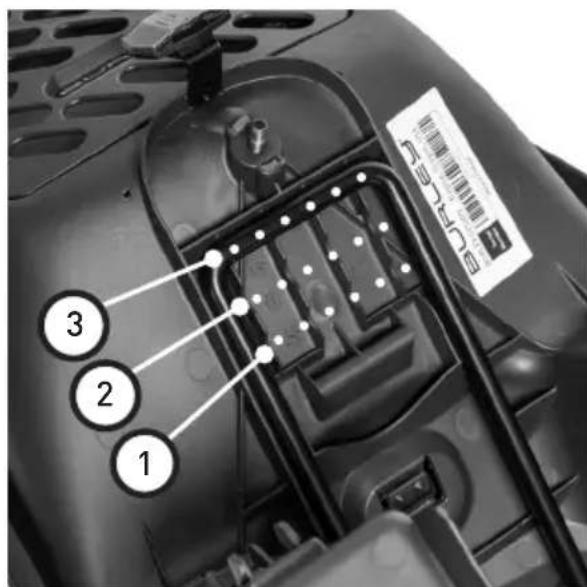
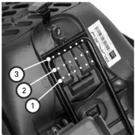
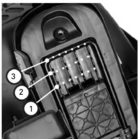
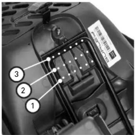
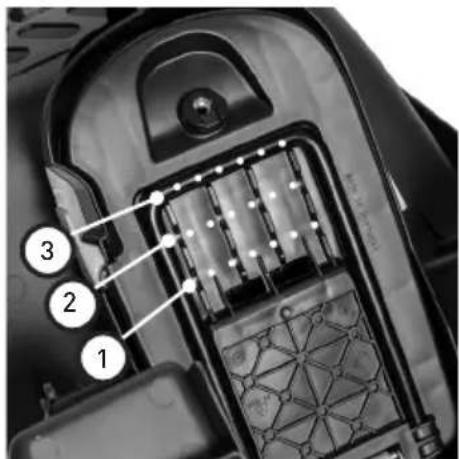
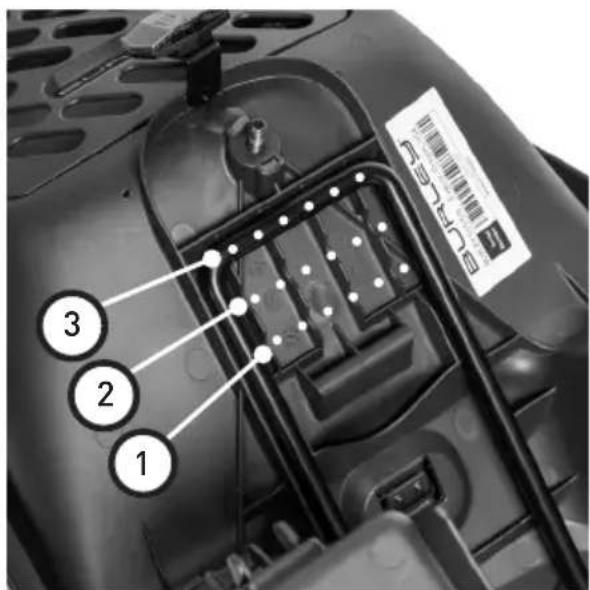
- For initial setup, align the Mounting Rails with position #3 on the underside of the Bicycle Seat [Figure 5].
NOTE: These 3 positions are for adjusting the horizontal position of the Bicycle Seat. See "Checking the Position of the Bicycle Seat" (Page 14) for further details.
-
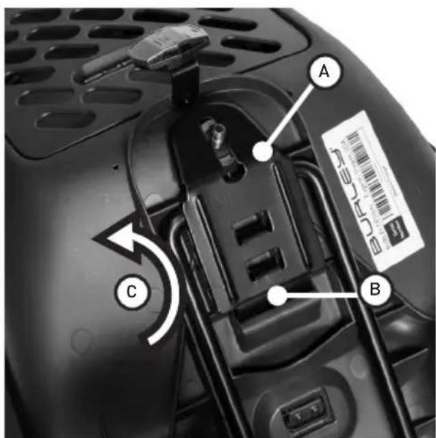
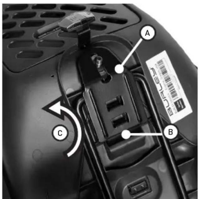
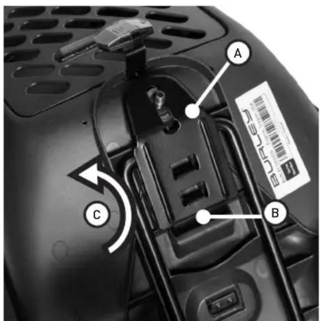
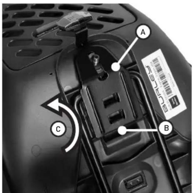
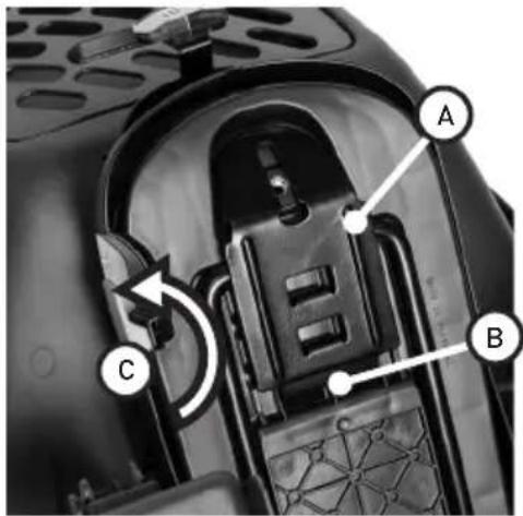
Insert the metal Base Plate [Figure 6a] into the slots on the underside of the Bicycle Seat [Figure 6b], and flip it closed [Figure 6c] so that the bolt passes through the slot in the Base Plate.
-
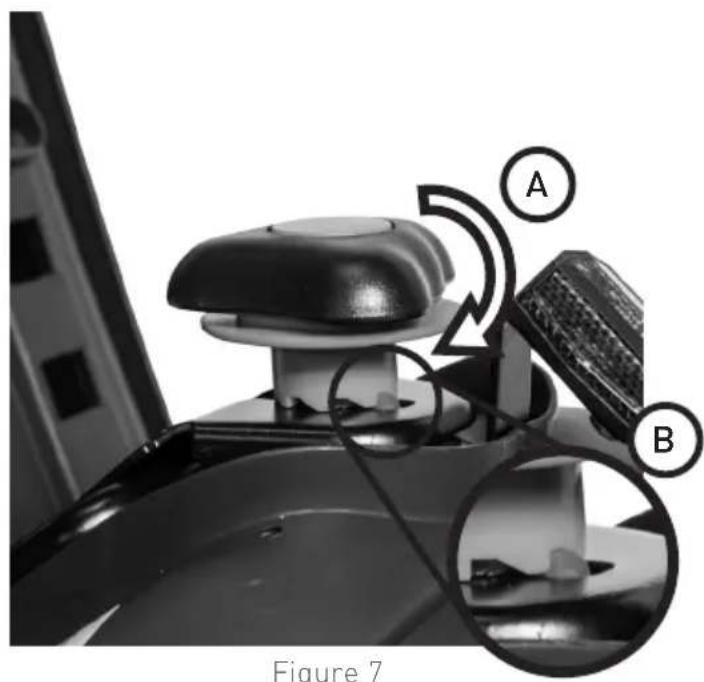
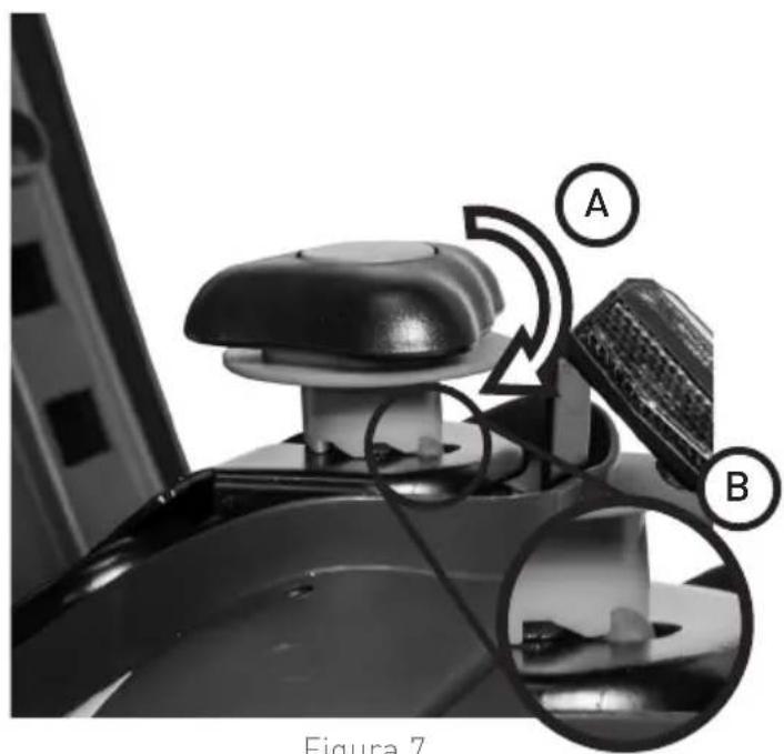
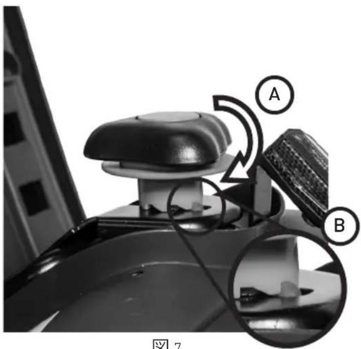
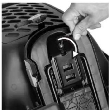
Re-attach the Mounting Knob to the bolt on the underside of the Bicycle Seat by rotating it clockwise [Figure 7a] until you cannot rotate it anymore.
NOTE: During the last few rotations of the Mounting Knob, the Locking Ring should make audible clicking noises. When fully tightened, the Locking Ring should prevent the Mounting Knob from rotating counter-clockwise [Figure 7b].
CAUTION: This step is extremely important for the safety of the child.
DASH FM
text_image
A B Figure 1 Figure 2 Figu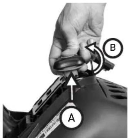
text_image
A B
natural_image
Close-up of a hand inserting a plug into a car body panel, with no visible text or symbols on the component itself.Figure 1 Figure 2 Figure 3
natural_image
Three-panel diagram showing a car interior with labeled parts and arrows indicating connection points (no text or symbols present)Figure 4
text_image
Labeled diagram of a vehicle interior showing numbered components and a barcode tagFigure 5
text_image
A B CFigure 6
text_image
A B Figure 7Figure 7
Attaching the Mounting Rails to Your Bicycle Seat
DASH X FM
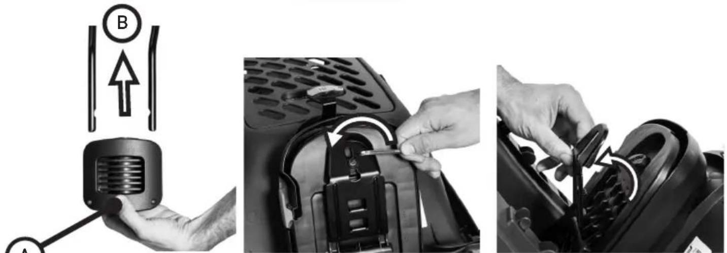
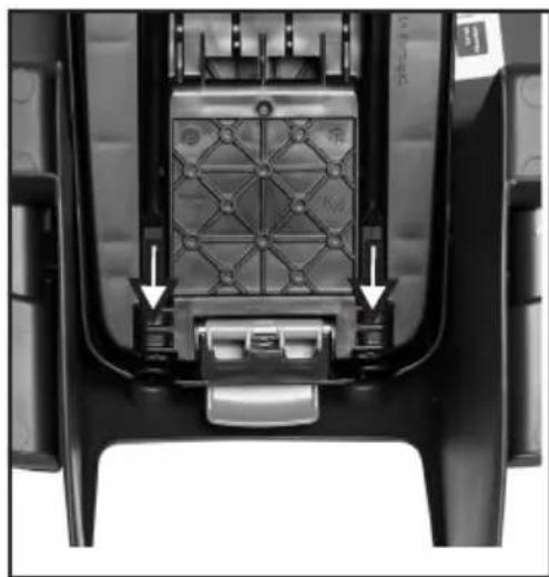
- Remove the Mounting Rails from the Mounting Block by depressing the front face of the Mounting Block [Figure 8a] and simultaneously pull the Mounting Rails out of the Mounting Block [Figure 8b].
NOTE: Pull both Mounting Rails from Mounting Block at the same time for smooth removal. - Remove the bolt connecting the Base Plate to the Bicycle Seat by rotating it counter-clockwise using the included Hex Wrench [Figure 9].
- Flip the Base Plate away from the Bicycle Seat and remove it from the slots on the underside of the Bicycle Seat [Figure 10].
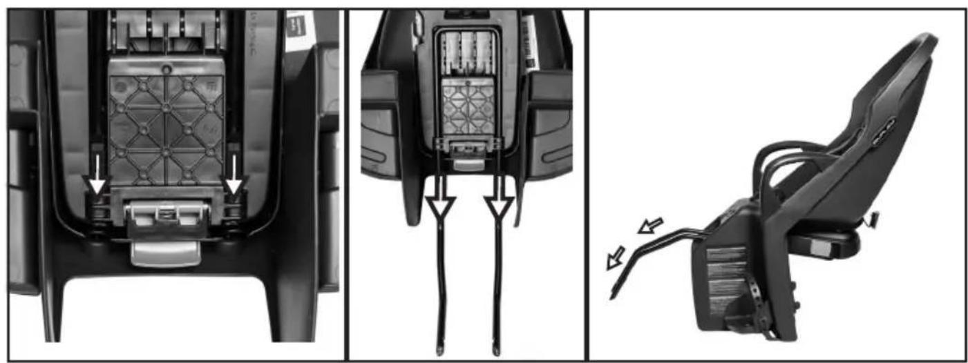
- Pass the Mounting Rails through the 2 holes between the legs of the Bicycle Seat [Figure 11].
NOTE: The orientation of the Mounting Rails should be such that they are bending downwards [Figure 11]. - For initial setup, align the Mounting Rails with position #3 on the underside of the Bicycle Seat [Figure 12].
NOTE: These 3 positions are for adjusting the horizontal position of the Bicycle Seat. See "Checking the Position of the Bicycle Seat" (Page 14) for further details. - Insert the metal Base Plate [Figure 13a] into the slots on the underside of the Bicycle Seat [Figure 13b], and flip it closed [Figure 13c].
- Re-attach the bolt by rotating it clockwise [Figure 14a] to a torque value of 8NM If you do not have a torque wrench, please visit a bicycle retailer to ensure proper installation.
⚠️ CAUTION: This step is extremely important for the safety of the child.
DASH X FM
text_image
Diagram showing three steps of a vehicle charging device: adding a sensor to a battery, adjusting the internal components, and adjusting the rear panel.Figure 8 Figure 9 Figure 10
natural_image
Three-panel diagram showing car seat components with arrows indicating fastening or adjustment, no text or symbols present.Figure 11

text_image
Technical diagram showing three views of a device's internal structure with numbered components and labeled parts A, B, C.Figure 14 Figure 13 Figure 1
Attaching the Frame Mounting System to Your Bicycle
-
Remove the Mounting Plate [Figure 15a] from the Mounting Block [Figure 15b] by using the provided Hex Wrench to remove the 4 screws and lock washers [Figure 15c].
-
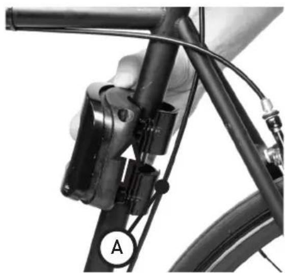
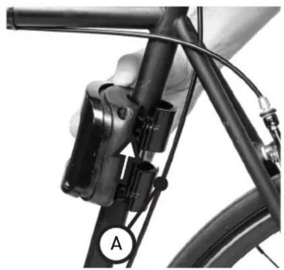
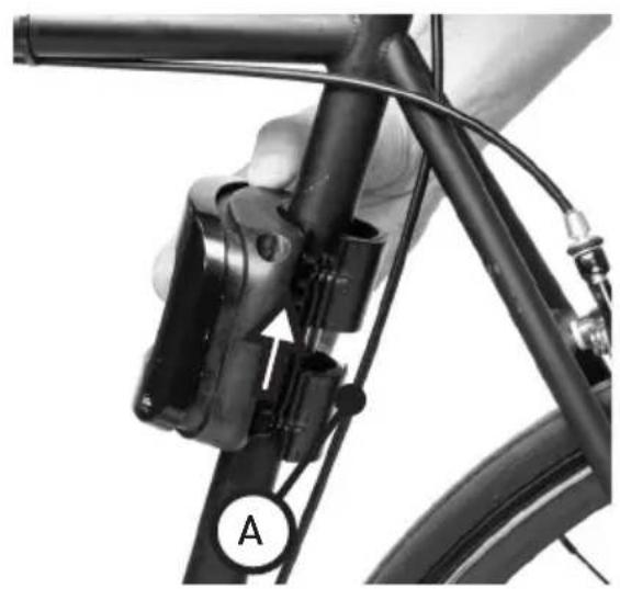
Open the Frame Protector on the Mounting Block wide [Figure 16], and wrap it around the Seat Tube of your bicycle, with the Mounting Block facing forward, and orient with the Mounting Rail holes facing upwards [Figure 17].
NOTE: If there are cables along this part of the frame, the Frame Protector should go underneath them so that there is nothing between it and the bicycle frame [Figure 17a].
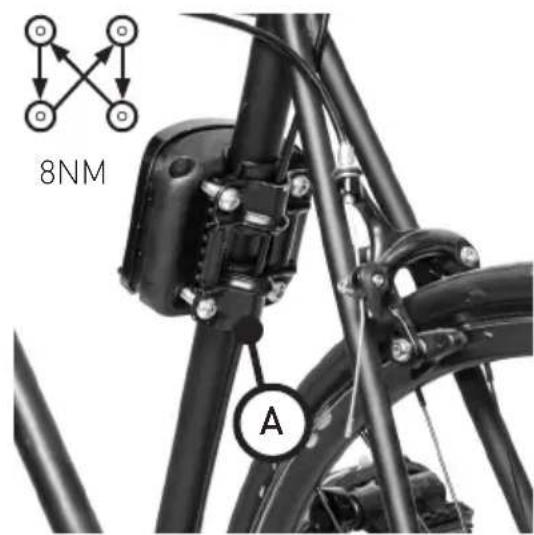
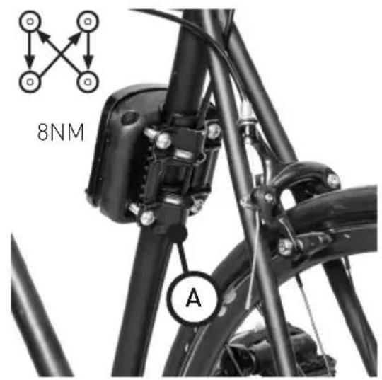
- Re-attach the Mounting Plate to the Mounting Block using the 4 screws with lock washers. Tighten the 4 screws in a crisscross pattern and in stages [Figure 18] to a torque value of 8NM. Check the security of the fasteners regularly. Ensure that the space between the Mounting Plate and Mounting Block is even on all sides.
NOTE: If there are cables along this part of the frame, they should be positioned so that they run along the central channel between the Frame Protector and Mounting Plate [Figure 18a].
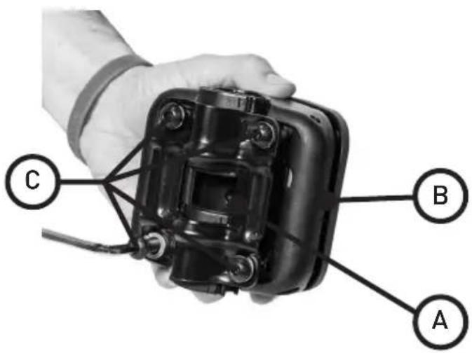
text_image
C B AFigure 15
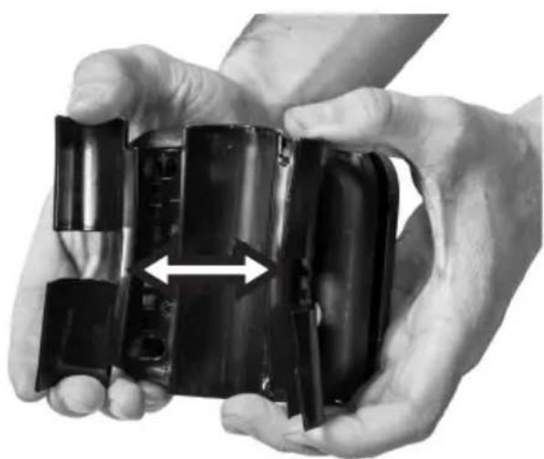
natural_image
Close-up of hands holding a black plastic device with a white bidirectional arrow indicating compression (no text or symbols visible)Figure 16
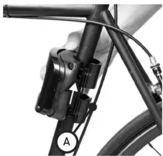
natural_image
Close-up of a bicycle's front wheel and cable assembly, showing mechanical components and a labeled section A (no text or symbols beyond label)Figure 17 Figure 18
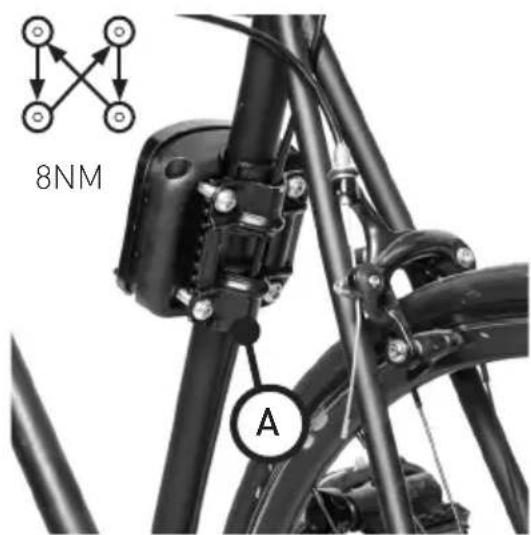
text_image
8NM AAttaching the Bicycle Seat to Your Bicycle
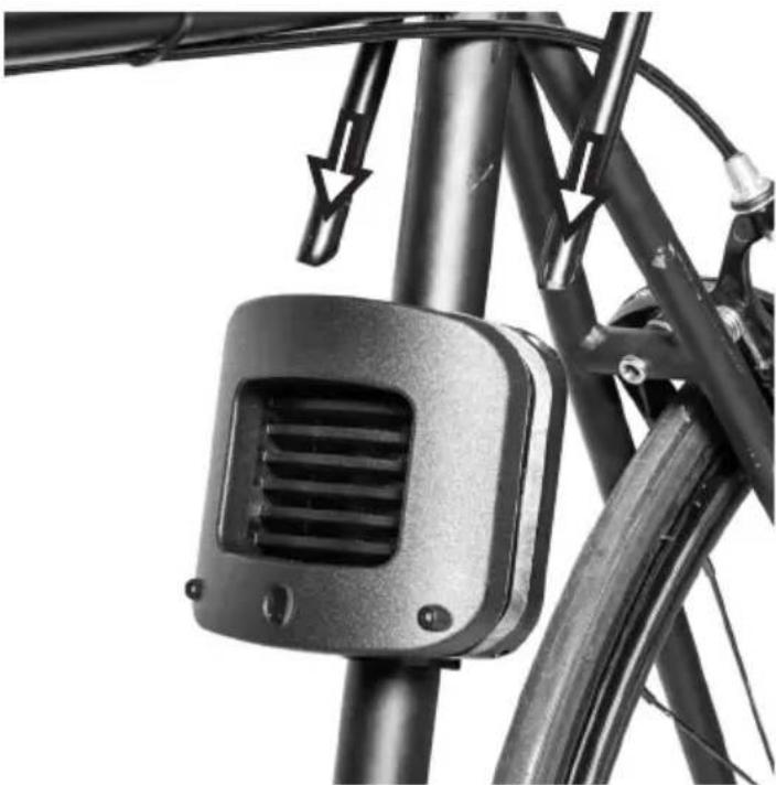
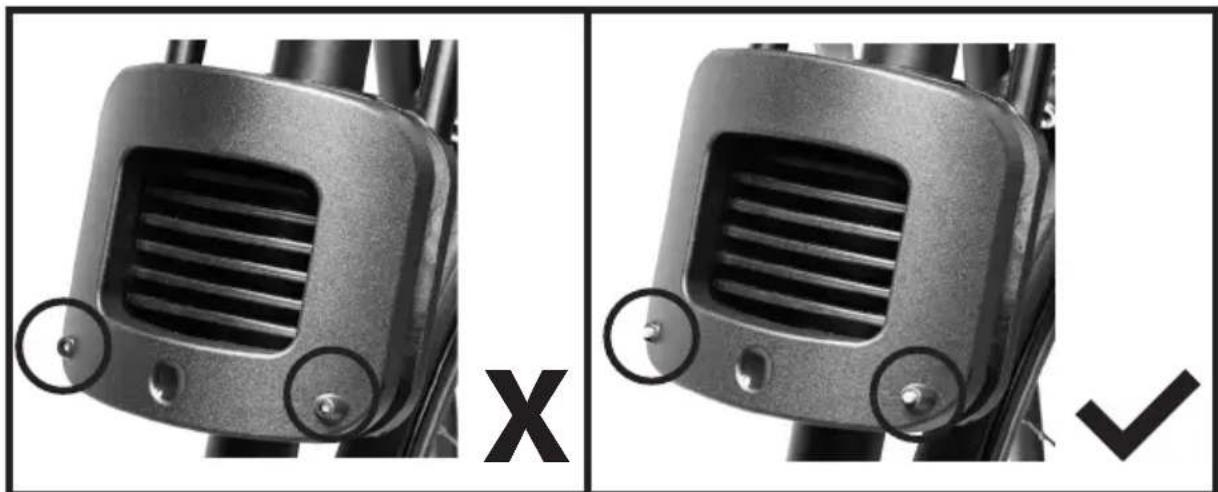
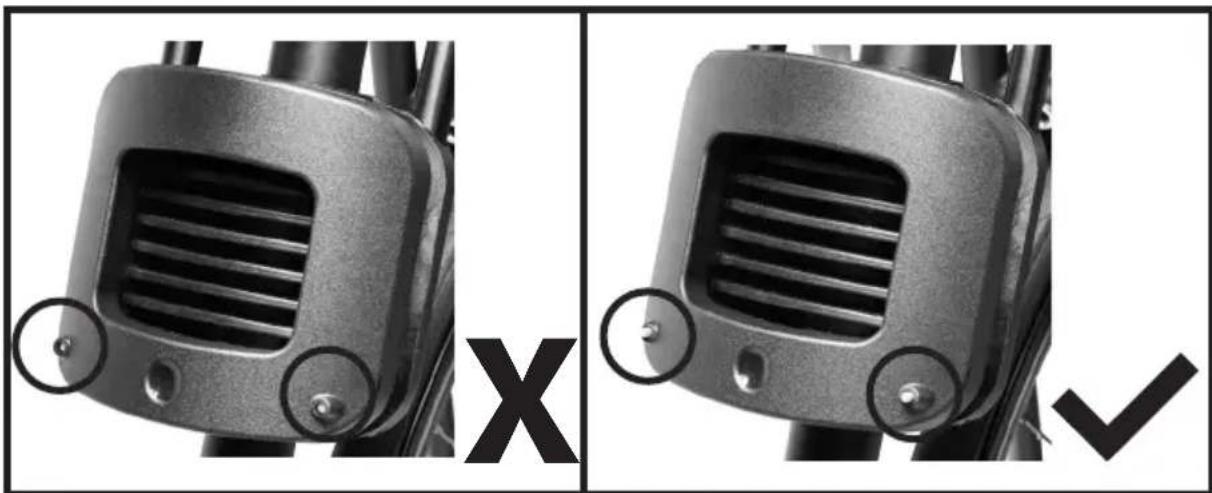
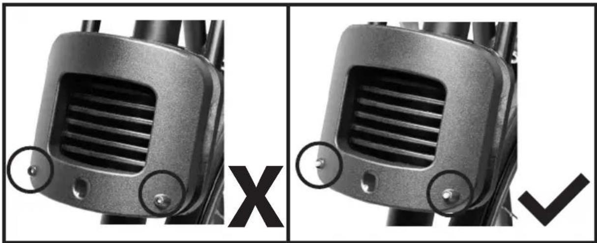
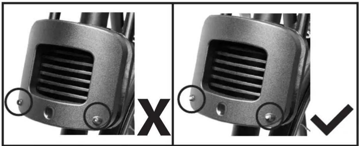
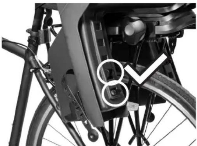
- Insert the Mounting Rails into the two holes on the top of the Mounting Block [Figure 19] until you hear an audible click and until the 2 green Safety Indicators pop out of the front of the Mounting Block [Figure 20].
CAUTION: This step is extremely important for the safety of the child.

WARNING
Do NOT proceed with using your Bicycle Seat until you check its Horizontal and Vertical Position, and secure the Safety Strap, as detailed on the following pages.
natural_image
Close-up of a bicycle's front wheel and side-mounted lock mechanism (no text or symbols visible)Figure 19
natural_image
Close-up of a mechanical component with ventilation grilles and mounting holes, shown in two different angles (no text or symbols)Figure 20
Checking the Position of the Bicycle Seat
1. Vertical Position:
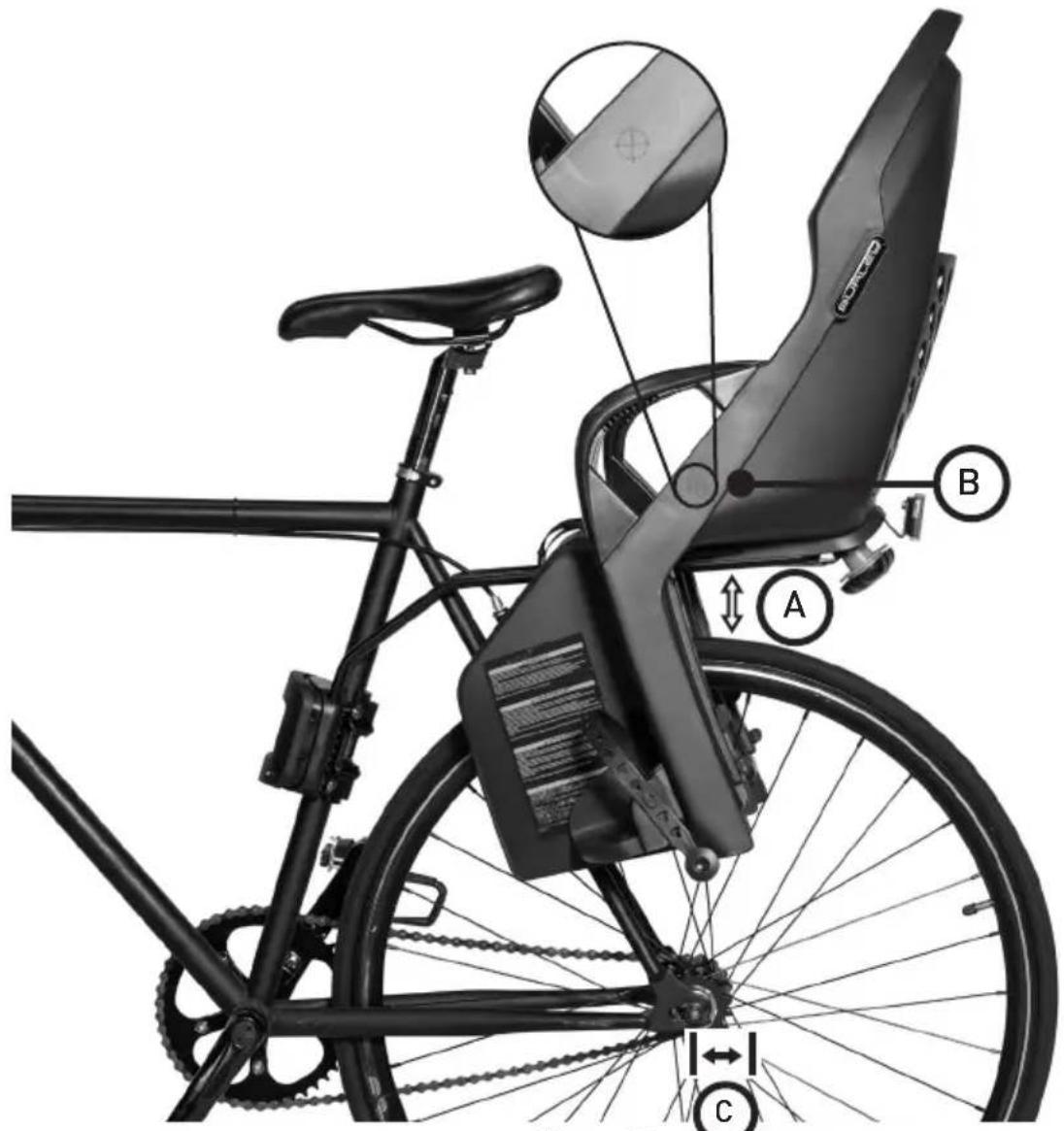
- The Base Plate on the bottom of the Bicycle Seat should be far enough away from the tire of the bicycle that they do not make contact when the Bicycle Seat is fully loaded.
- The maximum distance between the Base Plate and the bicycle tire, when the Bicycle Seat is unloaded, is 3.93 in (10 cm) [Figure 21a].
- If the Base Plate is too far from, or too close to, the bicycle wheel:
- Use the provided Hex Wrench to loosen the 4 screws connecting the Mounting Plate to the Mounting Block.
- Adjust the position of the Mounting Block on the Seat Tube until the Vertical Position of the Bicycle Seat is appropriate.
- Re-tighten the 4 screws using the provided Hex Wrench, per the instructions on Page 12.

CAUTION: This step is extremely important for the safety of the child.
2. Horizontal Position:
- The Bicycle Seat has a Center of Gravity Indicator, which is marked on the outer plastic shell [Figure 21b].
- The Center of Gravity Indicator MUST be positioned either:
- In front of the bicycle's rear wheel axle; or
- No more than 3.93 in (10 cm) behind the bicycle's rear wheel axle [Figure 21c].
- If the Center of Gravity Indicator is more than 3.93 in (10 cm) behind the Bicycle's rear wheel axle:
- Remove the Mounting Rails from the Mounting Block by following the instructions for "Removing the Bicycle Seat from your Bicycle" on Page 21.
- Detach the Mounting Rails from the Bicycle Seat by following the instructions for “Removing the Mounting Rails from your Bicycle Seat” on Page 21.
- Adjust the position (1, 2, or 3) that the Mounting Rails is aligned with on the underside of the Bicycle Seat [Figure 22], so that the Horizontal position of the Bicycle Seat is appropriate.
- Follow step 3 and 4 in the “Attaching the Mounting Rails to your Bicycle Seat” section on Page 8.

CAUTION: This step is extremely important for the safety of the child.
NOTE: Special care must also be taken when positioning the child seat to ensure that the cyclist does not touch the Bicycle Seat with his feet when cycling.
text_image
Diagram of a bicycle seat assembly with labeled parts A, B, and C, showing mechanical components and wiring.Figure 21
text_image
1 2 3Figure 22
Securing the Safety Strap
- Pass the Safety Strap around the Seat Tube and secure the buckle [Figure 23].
- Pull on the free end of the Safety Strap until it is tightly secured to the Bicycle frame [Figure 24].
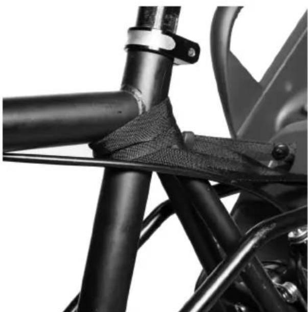
NOTE: Be careful to ensure that the free end of the Safety Strap is not able to come in contact with the wheel of the Bicycle. If needed, excess webbing material can be wrapped around the Seat Tube multiple times before securing the buckle (Figure 24a).

WARNING
Ensure that all parts of the bicycle function correctly when the Bicycle Seat is attached.
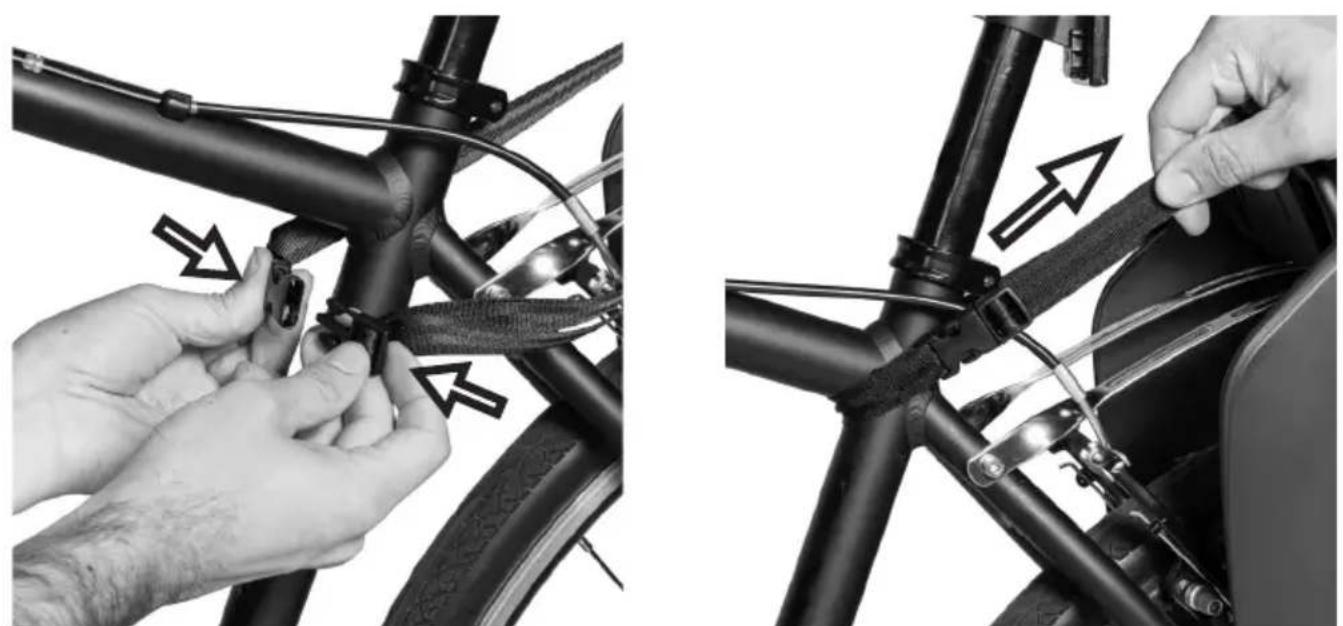
Figure 23 Figure 24
natural_image
Close-up of a motorcycle's front wheel and suspension bracket (no text or symbols visible)Figure 24a
| 16 | ENG | BURLEY | CHILD BIKE SEAT |
Securing the Child
-
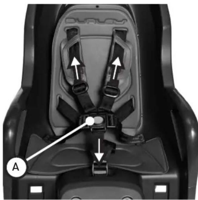
Before securing the child in the Bicycle Seat, ensure that the bicycle is stable, and the Bicycle Seat is securely attached to the bicycle. After the child is placed in the Bicycle Seat, secure and adjust the harness. Snap shoulder straps & waist straps into 5-point harness buckle and adjust straps so they fit securely [Figure 25].
-
To ensure the child's safety, secure their feet using the straps on the footrest [Figure 26]. Make sure that the child is comfortable and that the straps are not too tight.
NOTE: See the "Adjusting the Footrests" section (Page 18) for instructions on how to adjust the Footrest height.
- To remove the child, press the yellow release button on the 5-point harness [Figure 25a].

WARNING
Avoid serious injury from falling or sliding out. Always use 5-point harness.
text_image
DURLEY A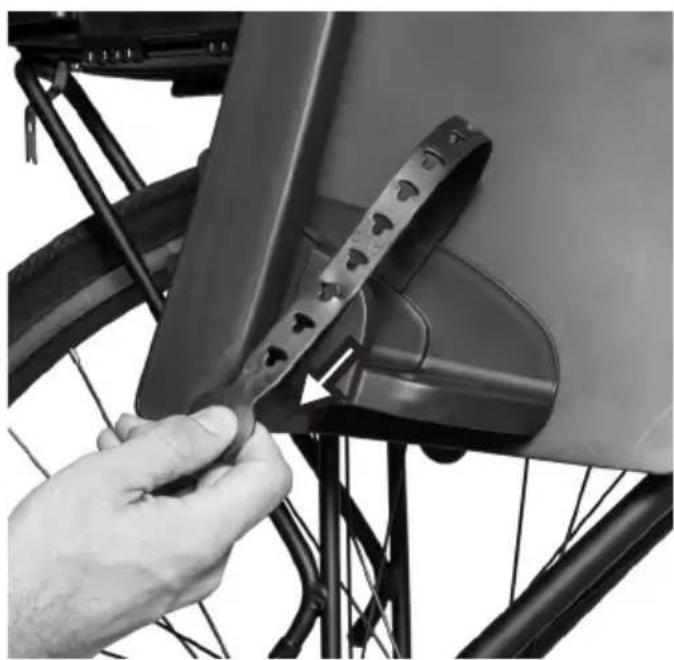
natural_image
Close-up of a hand adjusting a bicycle seatbelt component (no text or symbols visible)Figure 25 Figure 26
Adjusting the Footrests
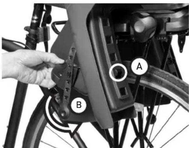
The height of each footrest can be adjusted to 4 different positions to ensure your child is comfortable and safe:
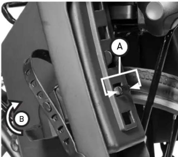
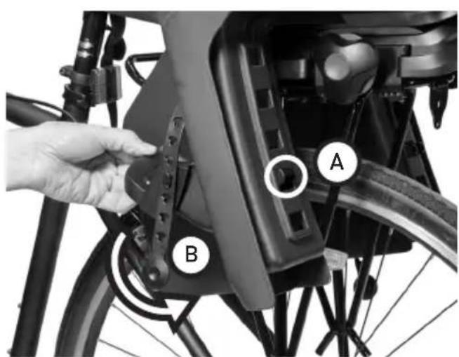
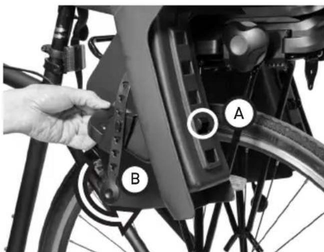
- Release each footrest from the Bicycle Seat by squeezing the rear tabs together [Figure 27a], and lifting the footrest up and away from the leg of the seat [Figure 27b].
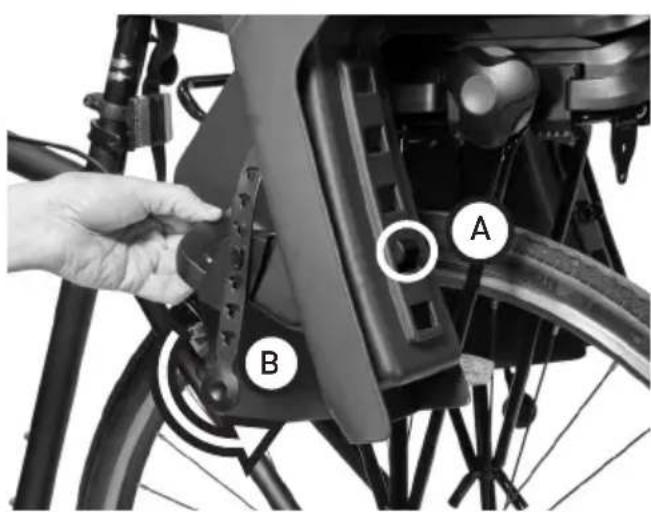
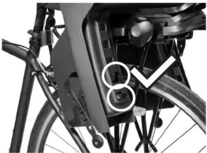
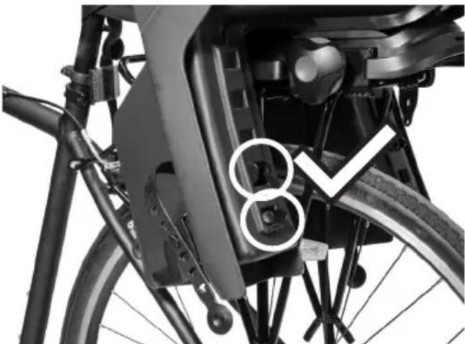
- To re-attach each footrest to the Bicycle Seat, engage the upper rear hook in the appropriate notch in the leg of the seat [Figure 28a], then rotate the footrest down and towards the leg of the seat [Figure 28b] until the rear tabs lock into the lower notch in the leg of the seat [Figure 29].
NOTE: For optimal comfort and safety, the footrest should be set at a height that allows the child's knee to bend at a 90^ angle.
text_image
Technical diagram of a vehicle suspension system with labeled components A and B, showing mechanical components and directional arrows.Figure 27
text_image
A BFigure 28
natural_image
Close-up of a bicycle's front wheel and side brackets, showing no visible text or symbolsFigure 29
| 18 | ENG | BURLEY | CHILD BIKE SEAT |
Adjusting the Harness
The upper shoulder strap attachment points have two positions that can be adjusted according to the child's size.
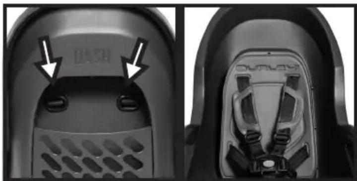
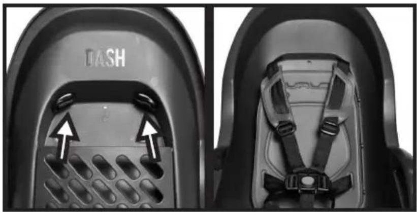
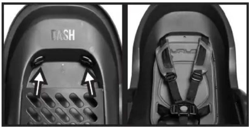
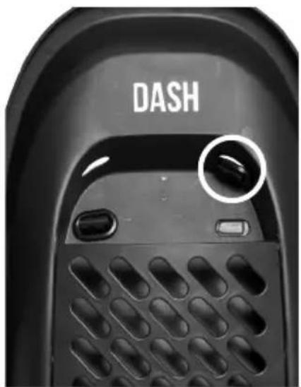
- Access the Harness Connector via the rear of the Bicycle Seat [Figure 30].
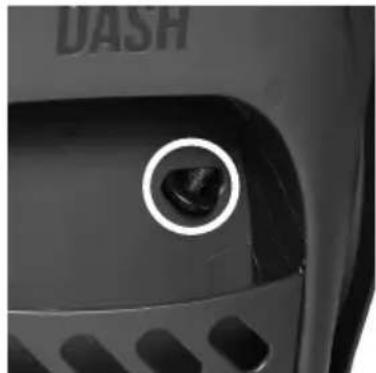
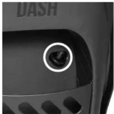
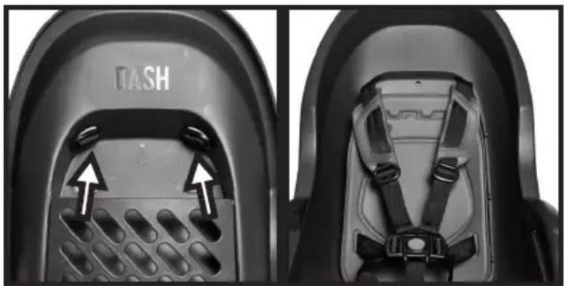
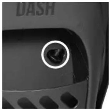
- Rotate the Harness Connector sideways, and slide it through the lower harness adjustment hole and the slot in the seat pad [Figure 31].
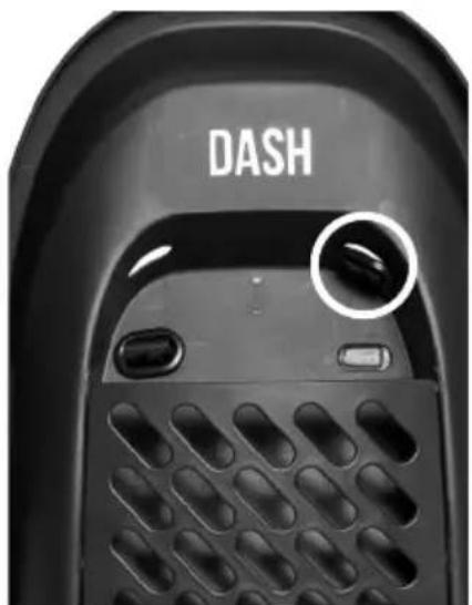
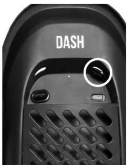
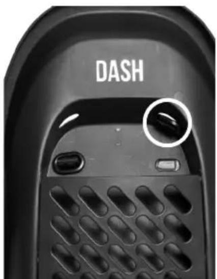
- Pass the Harness Connector through the upper harness adjustment hole, then rotate the Harness Connector so that it is secure against the rear seat back [Figure 32].
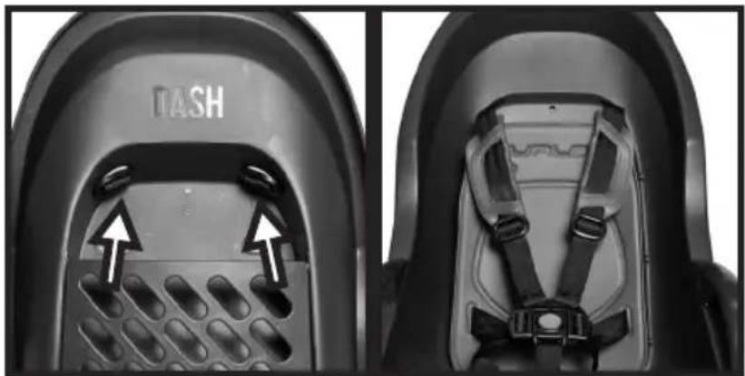
- Repeat steps 1-3 for the other shoulder strap. Ensure that harness straps are not twisted during harness adjustment [Figure 33].
NOTE: If you are adjusting from the upper harness position to the lower harness position, the Harness Connector will need to be passed back through the slot in the seat pad before passing it through the lower harness adjustment hole.
natural_image
Close-up of a black dash-shaped object with labeled features, shown from top and side (no text or symbols on the object itself)Figure 30
natural_image
Close-up of a car's front panel showing a circular button with a dark object, no visible text or symbols.Figure 31
text_image
DASHFigure 32 Figure 33
natural_image
Close-up of two black snowshoes with visible branding and decorative patterns, no text or symbols present.Adjusting the Recline of the Seat (Dash X FM only)
The Dash X FM has a system that allows you to adjust the recline angle of the Bicycle Seat from the standard 0^ , to either 10^ reclined or 20^ reclined by following the steps below:
- Detach the Safety Strap by releasing the buckle.
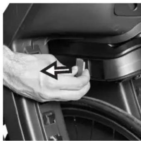
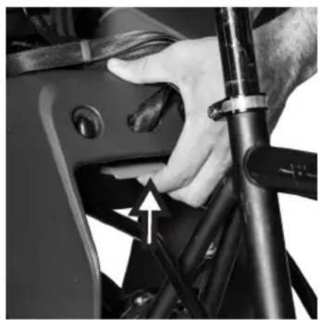
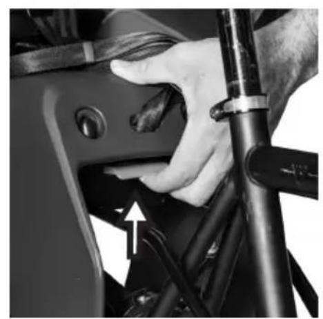
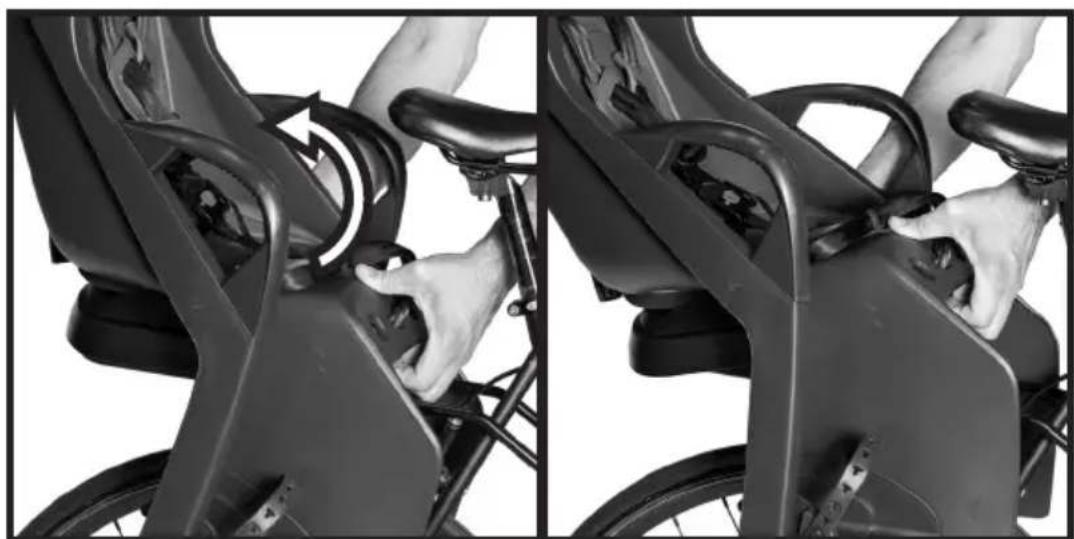
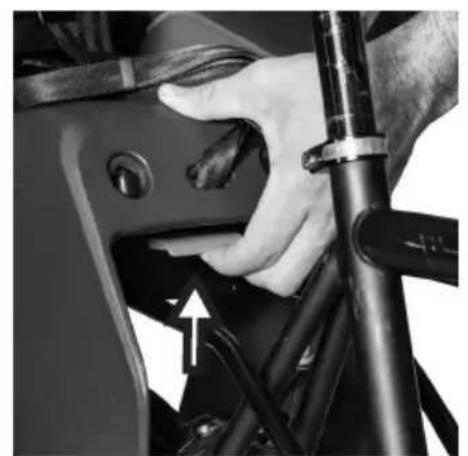
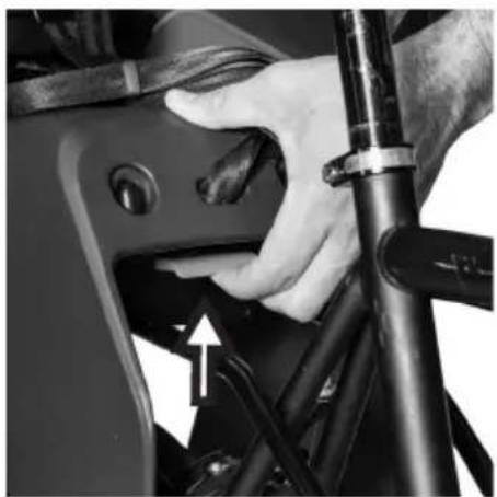
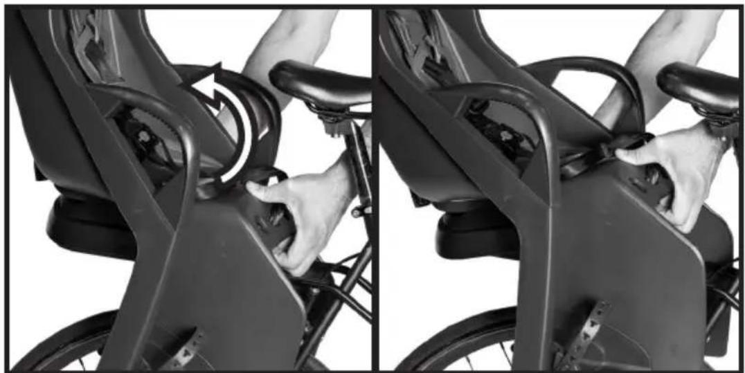
- Pull the Safety Lever away from the Recline Mechanism [Figure 34] and then lift the Recline Lever up [Figure 35].
- The Safety Lever can be released once you lift the Recline Lever.
-
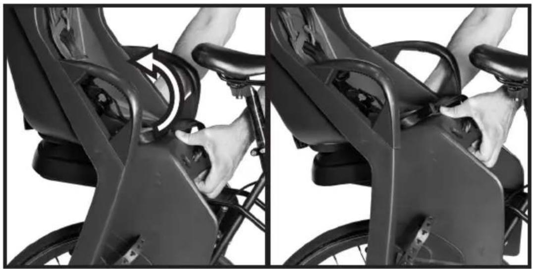
While lifting up on the Recline Lever, lift the front of the Bicycle Seat upwards to increase the recline angle [Figure 36].
-
Once the Bicycle Seat is in the desired 0°, 10°, or 20° recline, release the Recline Lever and close the Safety Lever so that it is flush with the side of the Recline Mechanism.
NOTE: Once the recline has been adjusted, make sure you re-attach the Safety Strap by following the instructions on Page 16.
natural_image
Close-up of a hand pressing a small component on a car wheel (no visible text or symbols)Figure 34 Figure 35
natural_image
Close-up of a hand adjusting a mechanical component with a tool, no visible text or symbols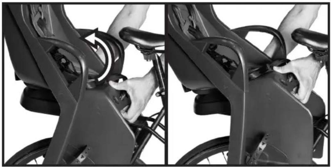
natural_image
Close-up of hands operating a bicycle seat frame, showing the wheel and seatbelt mechanism (no text or symbols visible)Figure 36
| 20 | ENG | BURLEY | CHILD BIKE SEAT |
Removing the Bicycle Seat from Your Bicycle
- Detach the Safety Strap by releasing the buckle.
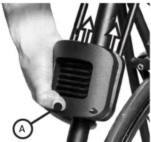
- Remove the Mounting Rails from the Mounting Block by depressing the front face of the mounting block [Figure 37a] and pulling the Mounting Rails out of the Mounting Block [Figure 37b].
NOTE: It is easiest to remove the Mounting Rails from the Mounting Block if you grab the front of the Bicycle Seat between the legs (where the Mounting Rails pass through the Bicycle Seat).
Removing the Frame Mounting Assembly from Your Bicycle
-
Remove the Mounting Plate from the Mounting Block by using the provided Hex Wrench to remove the 4 screws, while being careful not to lose the lock washers.
-
Remove the Mounting Block from the bicycle frame.
Removing the Mounting Rails from Your Bicycle Seat
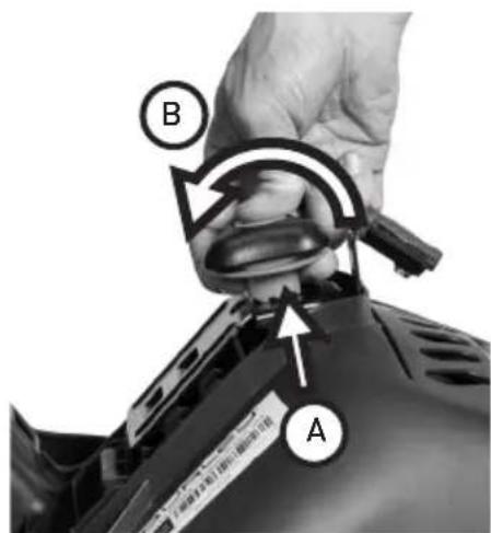
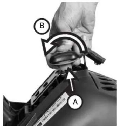
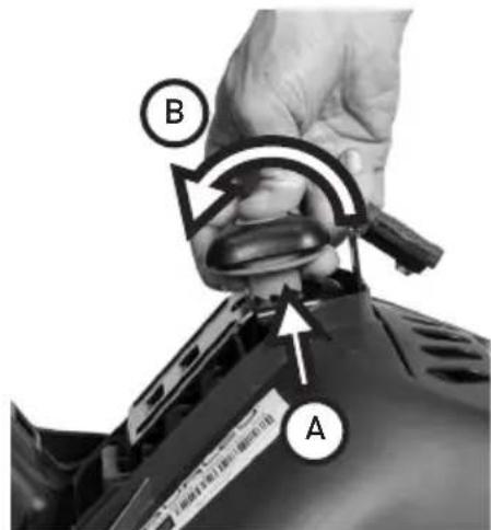
1a. Dash FM: Remove the Mounting Knob by pulling the Locking Ring towards the Mounting Knob [Figure 38a], and rotating the Mounting Knob counter-clockwise [Figure 38b].
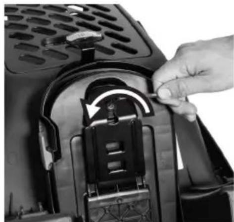
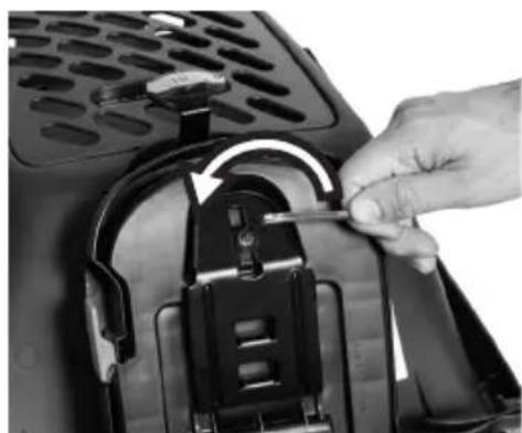
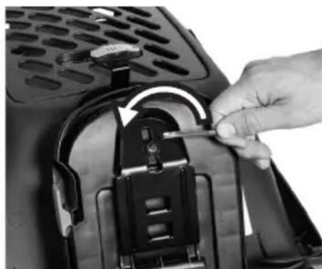
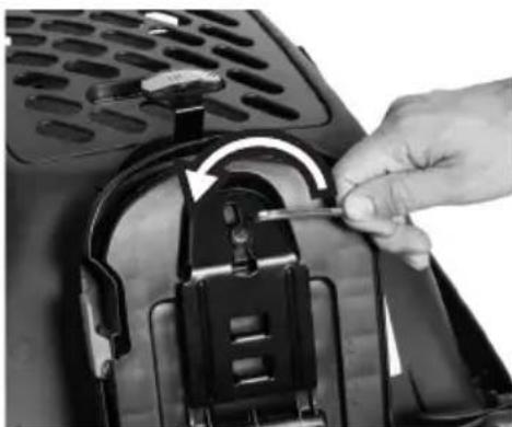
1b. Dash X FM: Remove the bolt by using the included Hex Wrench to rotate it counter-clockwise [Figure 39].
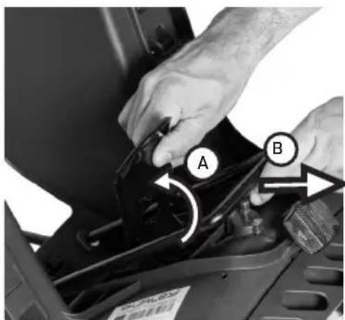
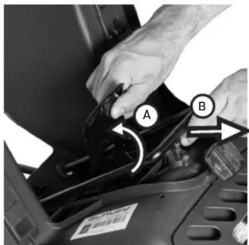
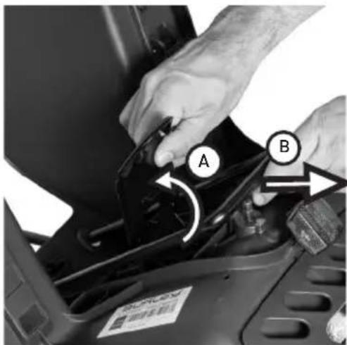
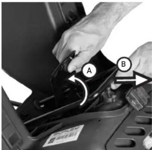
- Rotate the Base Plate away from the seat [Figure 40a] and then slide the Mounting Rails out through the 2 holes between the legs of the Bicycle Seat [Figure 40b].
natural_image
Close-up of a hand holding a bicycle lock and ventilation bracket (no text or symbols visible)Figure 37
text_image
B AFigure 38
natural_image
Close-up of a hand adjusting a mechanical component with a circular arrow indicating rotation (no text or symbols visible)Figure 39
text_image
A BFigure 40
Before You Ride:
Check before each use:
- Mounting Rails are securely attached to the Bicycle Seat
- Adjustment Knob is tightened properly and Locking Ring is engaged (Dash FM only)
- Frame Mounting Assembly is securely attached to the bicycle frame
- Mounting Rails are securely attached to the Mounting Block
- Safety Strap is secured to frame, and is not interfering with any moving parts
- Footrests are properly secured
- Safety Lever is flush against the side of the Recline Mechanism
- Height of the Bicycle Seat is no more than 3.93 in (10 cm) above the rear bicycle wheel, and does not contact wheel when fully loaded
- Center of Gravity of the Bicycle Seat is no more than 3.93 in (10 cm) behind the rear axle wheel of the bicycle
- All components of the bicycle still function correctly
- The Bicycle Seat does not interfere with braking, pedaling, or steering of the bicycle
- Load does not exceed 40 lbs (18 kg)
- Bicycle is in proper working order (refer to bicycle manufacturer's instructions)
- Passenger is wearing a helmet
- Child is properly secured with the 5-Point Harness
- Child's body, shoelaces, or toys cannot come in contact with any moving part of the seat or bicycle
- Lighting is adequate for riding conditions
- Ensure that any items stored in the rear storage compartment are under the maximum weight limit and secured. If items are not secured, they have risk of falling out while riding
- Inspect all components for damage
- Do not use the Bicycle Seat if any of the components are damaged.
- Damaged components must be replaced before using the Bicycle Seat.
Contact your authorized Burley dealer for replacement of any damaged or worn parts.
Maintaining Your Burley
Cleaning:
- Clean your Bicycle Seat with mild soap and water (do not use abrasive, corrosive or toxic products).
- Leave it to dry at room temperature.
Storage:
- For longer product life, store Bicycle Seat indoors and out of direct sunlight.
- The Bicycle Seat should not be stored at temperatures less than -4°F (-20°C) or greater than 149°F (65°C).
- The plastic Hanger that comes attached to your Bicycle Seat can be saved and used to store it against a wall.
Maximum Capacities
• Maximum Weight of Child: - 40 lbs (18 kg)
• Maximum Weight in Rear Storage Compartment:
- 2.2 lbs (1.0 kg)
• Maximum Nominal Load:
- 40 lbs (18 kg), one child + cargo
- Minimum Age of Child: 12 months*
*If child is younger than 12 months, consult a pediatrician
- Maximum Age of Child: 5 years*
*Regardless of age, child must not exceed weight limit
Connect with Burley:
Whether you ride your bike all year long or are a fair weather rider, Burley shares your enthusiasm for making the most of your bike. Thank you for your business. We appreciate it.




burley.com
Product Identification:
If you have any questions about the model name or year of your Burley, please consult our product identification web page: burley.com/support/what-year-is-my-burley
Burley Limited Warranty:
This Burley Bike Seat is warranted from the date of purchase against defects in materials and workmanship for 3 years. Your original dated sales or delivery receipt showing the date of purchase is your proof of purchase.
If a defect in materials or workmanship is discovered during the Limited Warranty period, we will, at our sole option, repair or replace your product at no cost to you. This warranty is only valid in the country in which the product was purchased.
The Limited Warranty extends only to the original retail purchaser of this product and is not transferable to anyone who obtains ownership of the product from the original purchaser.
The Limited Warranty does not cover claims resulting from misuse, failure to follow the instructions, improper installation, improper maintenance and use, abuse, alteration, involvement in an accident, and normal wear and tear. The Limited Warranty does not cover products which are used in rental operations and Burley will not be liable for any incidental or commercial damages relating to such use.
TO THE GREATEST EXTENT PERMITTED BY LAW, THIS LIMITED WARRANTY IS EXCLUSIVE AND IN LIEU OF ANY OTHER WARRANTY, WRITTEN OR ORAL, INCLUDING BUT NOT LIMITED TO ANY EXPRESS OR IMPLIED WARRANTY OF MERCHANTABILITY OR FITNESS FOR A PARTICULAR PURPOSE. The duration of any implied warranties, including any implied warranty of merchantability or fitness for a particular purpose that may exist during the express warranty period are expressly limited to the limited warranty period.
Some states and countries do not allow limitations on how long an implied limited warranty lasts; therefore, the above limitation and exclusions may not apply to you.
THE CUSTOMER'S EXCLUSIVE REMEDY FOR BREACH OF THIS LIMITED WARRANTY OR OF ANY IMPLIED WARRANTY OR OF ANY OTHER OBLIGATION ARISING BY OPERATION OF LAW OR OTHERWISE SHALL BE LIMITED AS SPECIFIED HEREIN TO REPAIR OR REPLACEMENT, AT OUR SOLE OPTION. IN ANY EVENT, RESPONSIBILITY FOR SPECIAL, INCIDENTAL AND CONSEQUENTIAL DAMAGES IS EXPRESSLY EXCLUDED.
Some states do not allow the exclusion of limitation of incidental or consequential damages, so the above limitation of exclusion may not apply to you.
Our goods come with guarantees that cannot be excluded under the Australian Consumer Law. You are entitled to a replacement or refund for a major failure and for compensation for any other reasonably foreseeable loss or damage. You are also entitled to have the goods repaired or replaced if the goods fail to be of acceptable quality and the failure does not amount to a major failure.
This Limited Warranty gives you specific legal rights, and you may have other rights that vary from state to state or country.
For warranty service or replacement part information for the USA or Canada, please contact Burley directly by calling 800-311-5294 or emailing burley@burley.com. For warranty service or replacement part information outside of the USA and Canada please contact the place of purchase for warranty service. Please be prepared to provide the product model, serial number and a description of the warranty issue.
Some replacement parts may be available for purchase after this limited warranty expires. Please visit us at www.burley.com or call us at 541-687-1644 for more information.
natural_image
Abstract black line drawing of a stylized rocket or rocket shape with no text or symbolsI 4.1 in | I 105 mm ∅ 1.10"-1.57" | ∅ 28-40 mm
natural_image
Simple line drawing of a bicycle wheel with spokes (no text or symbols)26", 650B/27.5" 700C, 29"
natural_image
Simple line drawing of an electric bicycle with a plug and cable (no text or symbols)text_image
Labeled diagram of a car safety seat assembly with numbered parts for identification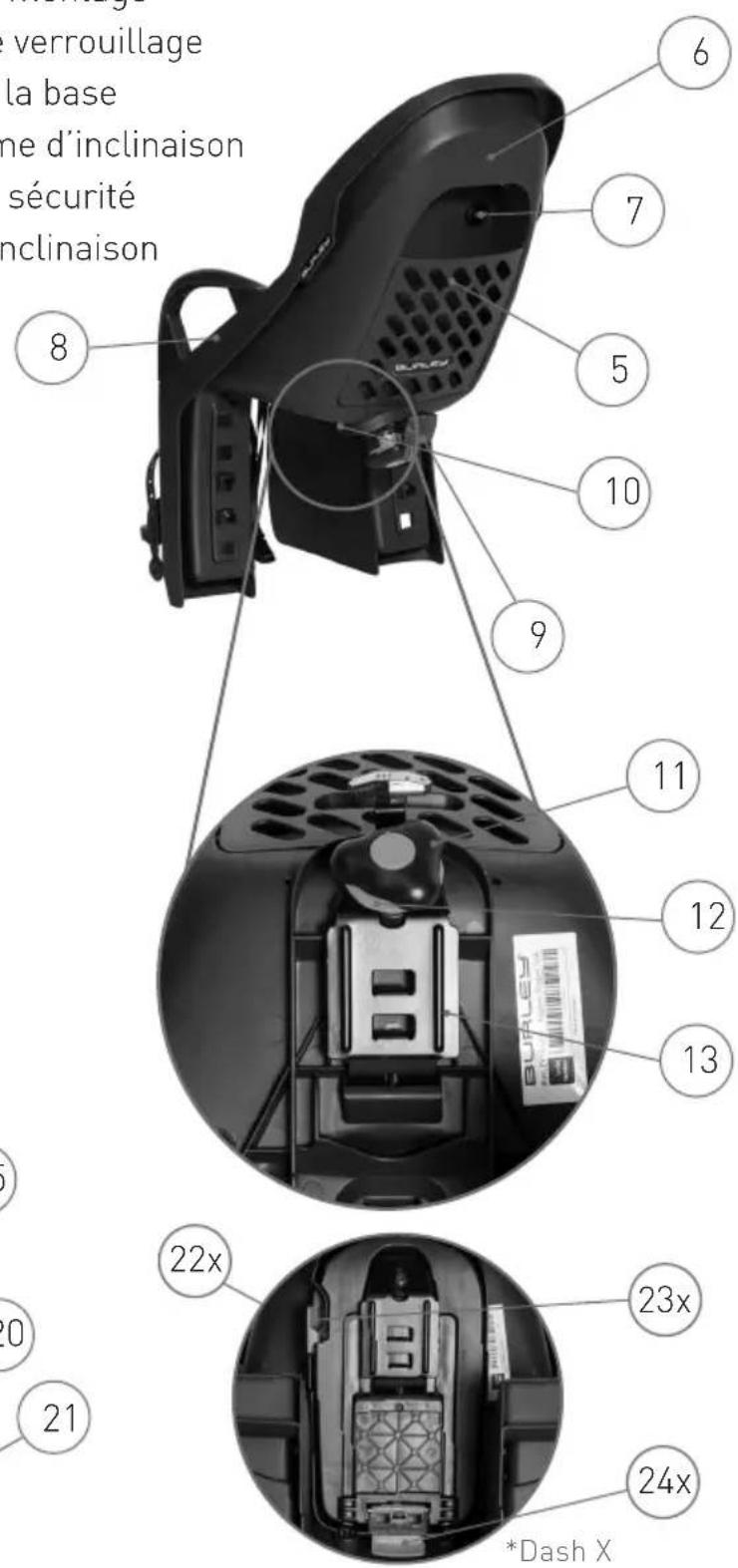
text_image
Labeled diagram of a mechanical or electrical component with numbered parts for identification.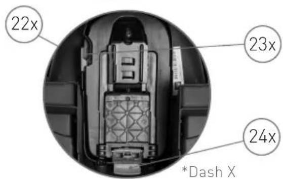
text_image
22x 23x 24x *Dash Xnatural_image
Close-up of a hand holding a tool near a car hood with a label and arrow indicating rotation (no readable text or symbols)Figure 1 Figure 2 Figure 3
natural_image
Three-panel diagram showing a camera seat assembly with labeled connectors and cable disassembled (no text or symbols present)Figure 4
text_image
Diagram of a device rear panel with numbered components and a barcode tag, likely for labeling or assembly.Figure 5
text_image
A B CFigure 6

text_image
A B Figure 7Figure 7
text_image
Diagram showing three steps of a device operation: adding a ventilation tube, adjusting the internal compartment, and adjusting the rear vent.Figure 8 Figure 9 Figure 10
natural_image
Three-panel diagram showing car seat components with arrows indicating fastening or adjustment, no text or symbols present.Figure 11
text_image
Technical diagram showing three views of a device's internal structure with numbered components and labeled parts A, B, C.Figure 14 Figure 13 Figure 12
natural_image
Close-up of hands holding a black plastic device with a white double-headed arrow indicating a compression or disassembly (no text or symbols visible)Figure 16
natural_image
Close-up of a bicycle's front wheel and cable assembly, showing mechanical components and a labeled section A (no text or symbols beyond label)Figure 17 Figure 18
text_image
8NM Anatural_image
Close-up of a bicycle's front wheel and side-mounted lock switch (no text or symbols visible)Figure 19
natural_image
Close-up of a mechanical component with ventilation grilles and mounting holes, showing two views (no text or symbols)Figure 20
text_image
Diagram of a bicycle seat assembly with labeled parts A, B, and C, showing mechanical components and wiring.Figure 21
text_image
Technical diagram of a vehicle engine compartment with numbered components and barcode labelFigure 22
natural_image
Close-up of a black bicycle wheel assembly with visible brackets and metal clamps (no text or symbols)Figure 24a
| 36 | FRA | BURLEY | REMORQUE ENFANT |
natural_image
Close-up of a hand adjusting a bicycle wheel rim component (no text or symbols visible)Figure 25 Figure 26
text_image
Technical diagram of a mechanical assembly with labeled components A and B, showing structural parts and directional arrows.Figure 27
text_image
A BFigure 28

natural_image
Close-up of a bicycle's front wheel and side-mounted sensors, showing no text or symbolsFigure 29
| 38 | FRA | BURLEY | REMORQUE ENFANT |
natural_image
Close-up of a black and white photo of a device's front panel showing internal components with arrows pointing to features (no text or symbols visible)Figure 30
natural_image
Close-up of a car's front panel showing a circular button with a dark object, no visible text or symbols.Figure 31
text_image
DASHFigure 32 Figure 33
natural_image
Close-up of two black DASH snowshoes showing seatbelt and vent slots (no text or symbols)natural_image
Close-up of a hand holding a small mechanical component, with no visible text or symbolsFigure 34
natural_image
Close-up of a hand holding a bicycle seatbelt with cable and a switch, no visible text or symbolsFigure 35
natural_image
Close-up of a person using a bicycle seatbelt mechanism, showing hand positioning and wheel alignment (no text or symbols visible)Figure 36
| 40 | FRA | BURLEY | REMORQUE ENFANT |
natural_image
Close-up of a hand holding a bicycle-mounted sensor or bracket with directional arrows indicating motion (no text or symbols visible)Figure 37
text_image
B AFigure 38
natural_image
Close-up of a hand using a tool to adjust or install a mechanical component, no visible text or symbolsFigure 39
text_image
Close-up of hands installing or adjusting a mechanical component with labeled parts A and B, showing directional arrows indicating assembly or repair.Figure 40
natural_image
Abstract black line drawing with curved and angular shapes, no text or symbols present1 4.1 in | 105 mm ∅ 1.10"-1.57" | ∅ 28-40 mm
natural_image
Simple line drawing of a bicycle wheel with spokes (no text or symbols)26", 650B/27.5" 700C, 29"
natural_image
Simple line drawing of a bicycle with an electric plug (no text or symbols)text_image
Exploded view diagram of a device with numbered parts for identification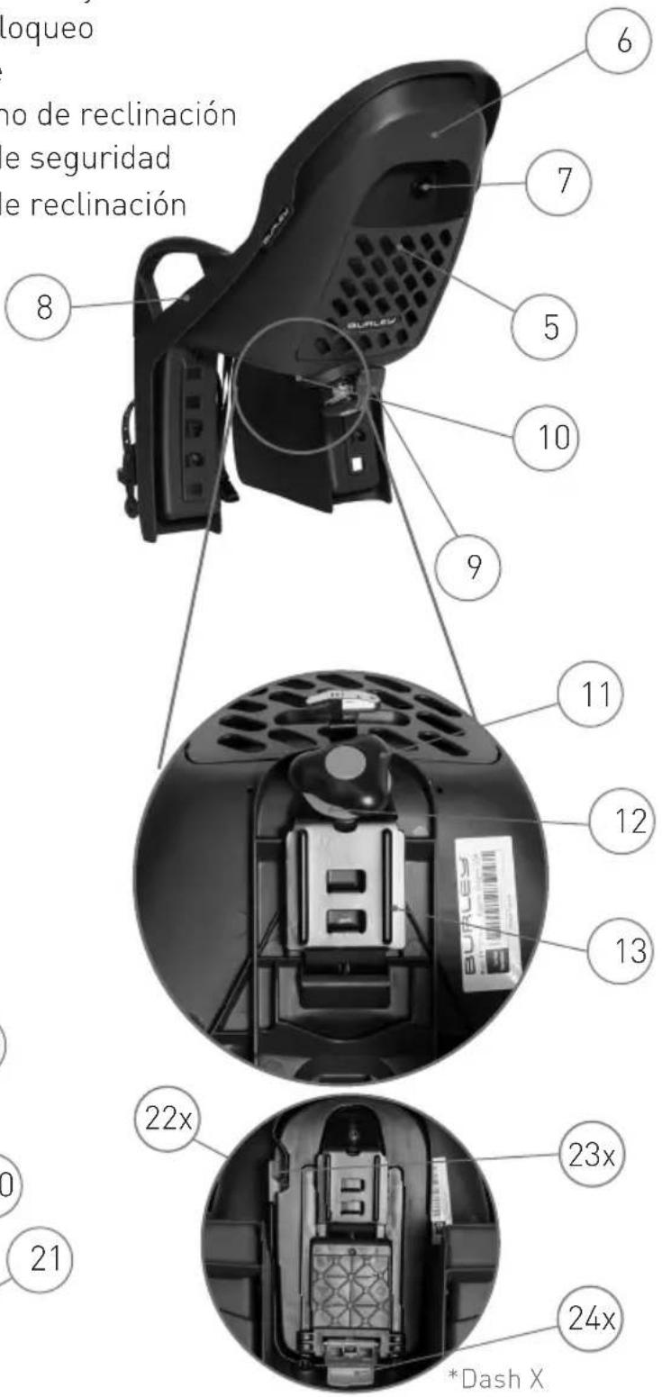
natural_image
Close-up of a hand holding a car hood with a cable being inserted, showing internal components and a label (no readable text or symbols)Figura 1 Figura 2 Figura 3
natural_image
Three-panel diagram showing a camera seat assembly with labeled parts and arrows indicating connection points (no text or symbols present)Figura 4
text_image
Labeled diagram of a device interior showing numbered components and a barcode tagFigura 5
text_image
A B CFigura 6
text_image
A B Figura 7Figura 7
text_image
Diagram showing three steps of a device operation: adding a ventilation tube, adjusting the internal compartment, and adjusting the rear vent.Figura 8 Figura 9 Figura 10
natural_image
Three-panel diagram showing car seat components with arrows indicating fastening or adjustment, no text or symbols present.Figura 11
text_image
Labeled diagram of a mechanical component with numbered parts 1, 2, and 3 pointing to internal structures.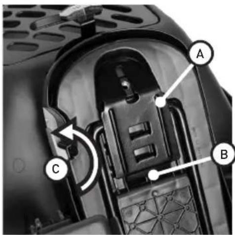
text_image
Technical diagram of a device's internal structure with labeled components A, B, and C, showing mechanical parts and directional arrows.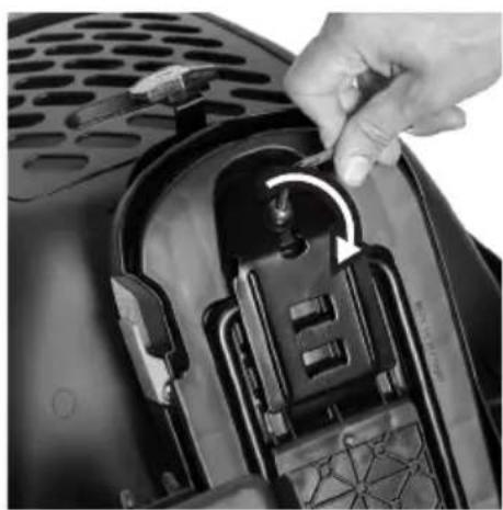
natural_image
Close-up of a hand inserting a spring into a device component (no visible text or symbols)Figura 14 Figura 13 Figura 12
natural_image
Close-up of hands holding a black plastic device with internal components, no visible text or symbolsFigura 16
natural_image
Close-up of a bicycle's front wheel and cable assembly, showing mechanical components and a labeled section A (no text or symbols beyond label)Figura 17 Figura 18
text_image
8NM Anatural_image
Close-up of a bicycle's front wheel and side-mounted sensor device (no text or symbols visible)Figura 19
natural_image
Close-up of a mechanical component with ventilation grilles and mounting holes, showing two side-by-side views (no text or symbols)Figura 20
natural_image
Close-up of a black bicycle support structure with visible mechanical components and no text or symbolsFigura 24a
| 56 | ESP | BURLEY* | ASIENTO INFANTIL PARA BICICLETAS |
natural_image
Close-up of a hand adjusting a bicycle seat cover with a plastic buckle (no text or symbols visible)text_image
Technical diagram of a mechanical assembly with labeled components A and B, showing structural parts and motion indicators.Figura 27
text_image
A BFigura 28
natural_image
Close-up of a bicycle's front wheel and side brackets, showing no visible text or symbolsFigura 29
| 58 | ESP | BURLEY | ASIENTO INFANTIL PARA BICICLETAS |
natural_image
Close-up of a car's front panel showing a dark knob with a white circle highlighting the center (no text or symbols visible)Figura 31
text_image
DASHFigura 32 Figura 33
natural_image
Close-up of two black TASH snowshiculars showing seatbelt and vent slots, with arrows indicating movement or force direction (no text or symbols on the objects themselves)natural_image
Close-up of a hand holding a small mechanical component, with no visible text or symbolsFigura 34
natural_image
Close-up of a hand holding a black mechanical component with wires and a bracket (no visible text or symbols)Figura 35
natural_image
Close-up of hands operating a bicycle seatbelt mechanism, showing the wheel and seat assembly (no text or symbols visible)Figura 36
| 60 | ESP | BURLEY | ASIENTO INFANTIL PARA BICICLETAS |
natural_image
Close-up of a hand holding a bicycle-mounted sensor or bracket with directional arrows indicating motion (no text or symbols visible)Figura 37
text_image
B AFigura 38
natural_image
Close-up of a hand using a tool to adjust or install a mechanical component, no visible text or symbolsFigura 39
text_image
A BFigura 40
natural_image
Abstract black line drawing of a stylized arrow or arrowhead with a double-headed arrow, no text or symbols present.1 4.1 in | 105 mm ∅ 1.10"-1.57" | ∅ 28-40 mm
natural_image
Simple line drawing of a bicycle wheel with spokes (no text or symbols)26", 650B/27.5" 700C, 29"
natural_image
Simple line drawing of a bicycle with an electric plug (no text or symbols)電動アシスト自転車対応
text_image
Exploded view diagram of a car seat with numbered parts for identification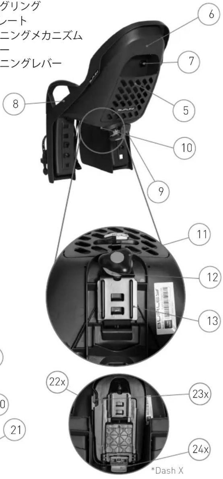
natural_image
Close-up of a hand holding a car hood with a cable being inserted, showing internal components and a label (no readable text or symbols)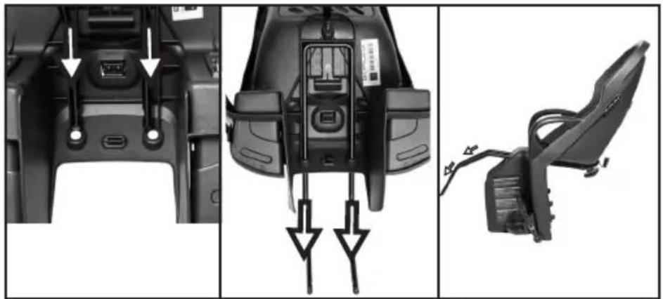
natural_image
Three-panel diagram showing a camera seat assembly with labeled parts and arrows indicating connection points (no text or symbols present)图4
text_image
Labeled diagram of a device interior with numbered components and a barcode tag图5
text_image
A B C图6
text_image
A B 图 7图7
natural_image
Close-up of a hand using a tool to adjust or install a mechanical component with a curved arrow (no visible text or symbols)
natural_image
Close-up of a hand adjusting a black mechanical component with a tool, no visible text or symbols図8図9図10
natural_image
Close-up of a mechanical component with a grid-patterned central panel and two arrows pointing to features (no visible text or symbols)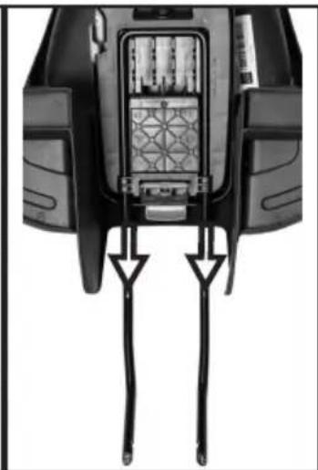
natural_image
Close-up of a mechanical component with two vertical strips and a star-patterned internal structure (no visible text or symbols)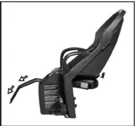
natural_image
Black automotive seat assembly with visible wiring and mounting bracket (no text or symbols)图11
text_image
Labeled diagram of a device interior showing numbered components: 1, 2, and 3.图12
text_image
Technical diagram of a device's internal structure with labeled components A, B, and C图13
natural_image
Close-up of a hand inserting a plug into a black electronic device component (no visible text or symbols)图14
natural_image
Close-up of hands holding a black plastic device with a white bidirectional arrow indicating compression (no text or symbols visible)图16
natural_image
Close-up of a bicycle's front wheel and side-mounted brake caliper (no text or symbols visible)图17

natural_image
Close-up of a bicycle's front wheel and suspension bracket with labeled component A (no text or symbols beyond labels)图18
自転車に自転車用シートを取り付ける
natural_image
Close-up of a bicycle's front wheel and side-mounted sensor device (no text or symbols visible)图19
natural_image
Close-up of two mechanical components with ventilation grilles, one labeled 'X' and the other checked with a checkmark (no text or symbols on the components themselves)图20
自転車用シートの位置を確認する
1. 垂直方向の位置:
text_image
Diagram of a bicycle seat assembly with labeled parts A, B, and C, showing mechanical components and wiring.图21
text_image
1 2 3图22
natural_image
Close-up of a black bicycle wheel assembly with visible brackets and textured grip (no text or symbols)图 24a
natural_image
Close-up of a hand adjusting a bicycle seatbelt component (no text or symbols visible)图26
フットレストを調 節する
text_image
Technical diagram of a mechanical assembly with labeled parts A and B, showing structural components and directional arrows.图27
text_image
A B图28
natural_image
Close-up of a bicycle's front wheel and side-mounted sensors, showing no text or symbols图29
natural_image
Close-up of a black helmet with 'DASH' label and two arrows pointing to the front panel (no text beyond label)图30
natural_image
Close-up of a car's front panel showing a circular button with a black hole, no visible text or symbols图31
text_image
DASH图32
natural_image
Close-up of a TASH-branded scooter seat with visible seats and buttons, showing front and side views (no text or symbols on the main body)图33
natural_image
Close-up of a hand holding a small mechanical component, with an arrow indicating left motion (no text or symbols visible)图34
natural_image
Close-up of a hand adjusting a black mechanical component with a cable and bracket (no visible text or symbols)图35
natural_image
Close-up of a person using a bicycle seatbelt mechanism, showing hand positioning and wheel alignment (no text or symbols visible)图36
natural_image
Close-up of a hand holding a bicycle-mounted sensor or bracket with directional arrows indicating motion (no text or symbols visible)图 37

text_image
B A图 38
natural_image
Close-up of a hand using a tool to adjust or install a mechanical component, no visible text or symbols图 39
text_image
A B图40