
OCEAHC440S9 - Range hood OCEANIC - Free user manual and instructions
Find the device manual for free OCEAHC440S9 OCEANIC in PDF.

| Product type | Cooker hood (extraction and recirculation) |
| Brand | Oceanic |
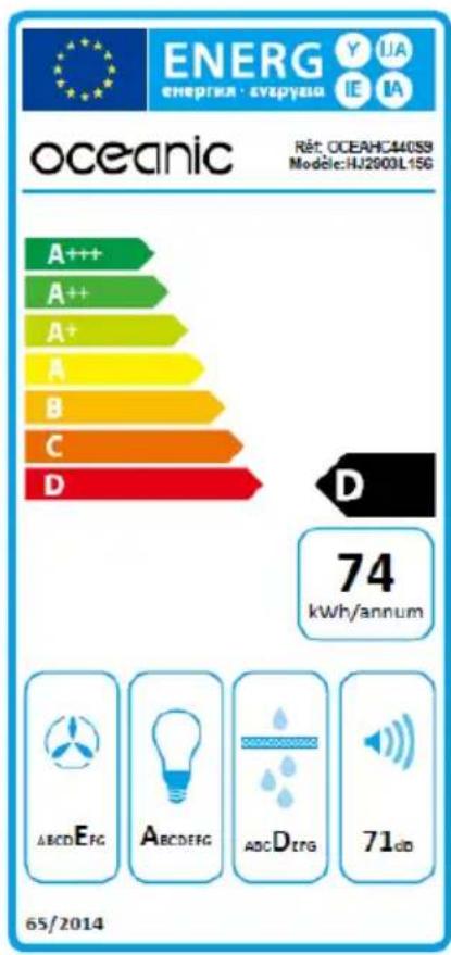
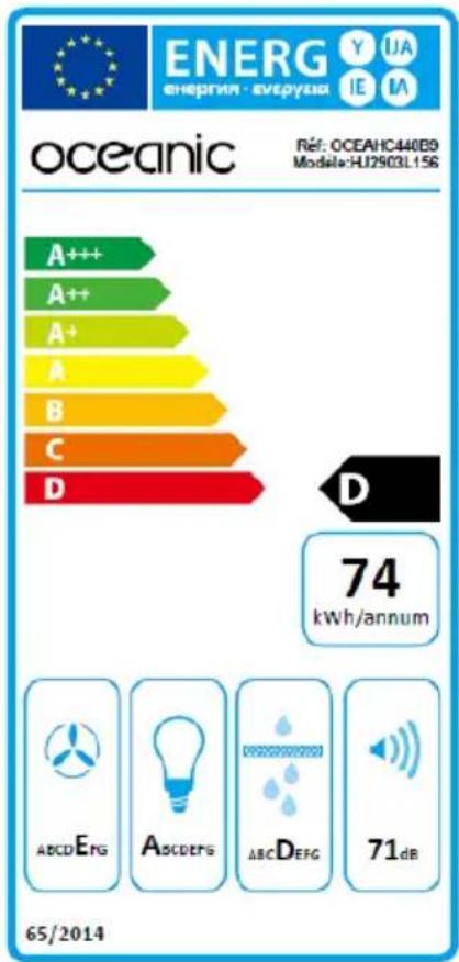
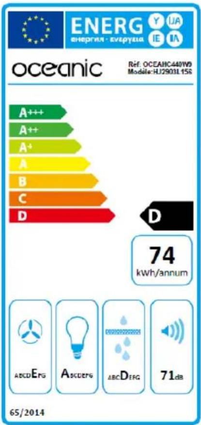
| Model | OCEAHC440S9 (also OCEAHC440B9/W9) |
| Power supply | 220-240 V ~ 50 Hz |
| Energy efficiency class | D |
| Annual energy consumption | 73.4 kWh/year |
| Maximum airflow rate | 332.4 m³/h |
| Sound pressure level | 71 dB(A) |
| Lighting | 2 non-replaceable LED lamps (2 W total) |
| Number of speeds | 3 (low, medium, high) + stop |
| Operating modes | Extraction (external exhaust) and recirculation (charcoal filter) |
| Grease filter | Washable metal filter (monthly cleaning recommended) |
| Charcoal filter | Flat charcoal filter, replacement every 3 months or 120 h of use |
| Installation | Wall or under cabinet (mounting included) |
| Safety distance (gas) | 800 mm between hob and hood |
| Safety distance (electric) | 700 mm |
| Exhaust duct diameter | 150 mm maximum |
| Maximum duct length | 2.5 m |
| Control | Push buttons on control panel |
| Non-return valve | Included |
Frequently Asked Questions - OCEAHC440S9 OCEANIC
User questions about OCEAHC440S9 OCEANIC
0 question about this device. Answer the ones you know or ask your own.
Ask a new question about this device
Download the instructions for your Range hood in PDF format for free! Find your manual OCEAHC440S9 - OCEANIC and take your electronic device back in hand. On this page are published all the documents necessary for the use of your device. OCEAHC440S9 by OCEANIC.
USER MANUAL OCEAHC440S9 OCEANIC
natural_image
Exterior view of a stainless steel DSBHC air purifier with ventilation grilles and control knobs (no text or symbols visible)OCEAHC440S9
OCEAHC440B9
OCEAHC440W9
oceanic
Installation (Mode extraction) 12
Installation (Mode recyclage)....14
INSTALLATION (Fixation murale)....16
| Index | Description | Illustration | Quantité |
| PL-1 | Caisson de la hotte | 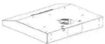 | 1 |
| PL-2 | Sortie d’évacuation / Clapet anti-retour | 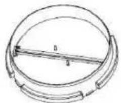 | 1 |
| PL-3 | Couvercle rond | 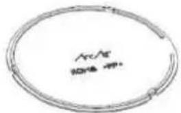 | 1 |
| PL-4 | Vis (ST4 * 30 mm) | 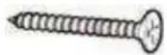 | 6 |
| PL-5 | Filtre plat carbone |  | 2 |
Installation (Mode extraction)
natural_image
Diagram of airflow around a mechanical component with directional arrows indicating movement (no text or symbols)natural_image
Simple line drawing of a mechanical component with a circular top and base (no text or symbols)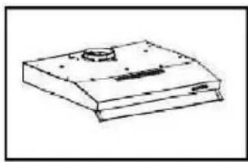
natural_image
Simple line drawing of a rectangular electronic device with a central button and mounting holes (no text or symbols)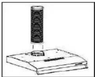
natural_image
Simple line drawing of a cylindrical object above a rectangular base (no text or symbols)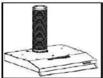
natural_image
Simple line drawing of a cylindrical object mounted on a base (no text or symbols)Installation (Mode recyclage)
natural_image
Diagram of a mechanical or fluid system with directional arrows indicating flow or movement (no text or symbols)natural_image
Illustration of a hand holding a plug with a cable, pointing at a wall-mounted panel (no text or symbols)natural_image
Technical line drawing of a device with exploded view and internal components (no text or symbols)natural_image
Pure diagram of a rectangular frame with arrows indicating upward motion (no text or symbols)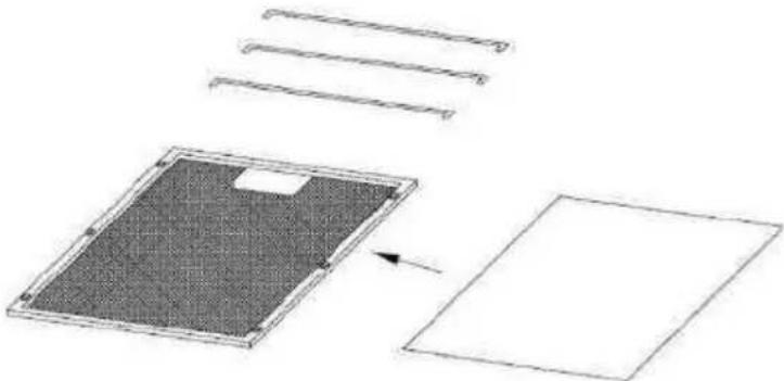
natural_image
Diagram showing a device with a grid, panel, and sheet components (no text or symbols)natural_image
Symbolic representation of a trash bin with crossed lines indicating no waste or discharge (no text or labels)Read this guide carefully before installing and using this product and keep it for future reference.
Thank you for choosing Oceanic. This Use and Maintenance Guide is designed to provide you with all the necessary information regarding the installation, use and maintenance of the appliance.
In order to operate the unit properly and securely, read this user guide carefully before installing and using the product.
Contents
Find some informations....28
Important safety instructions.... 29
Lamp.... 34
Product Description 35
Description of the pieces.... 36
Installing the hood....37
Installation (Mode extraction) : 37
Installation (Mode recycling) 39
Recommendations for wall mounting....40
Preparation before installation....41
INSTALLATION (Fixing on wall) 41
INSTALLATION (Fixing under a cupboard) 43
Adjusting the ventilation 45
Information about the carbon flat filter 46
Cleaning 47
Control Panel Functions....48
Help 49
Technical informations....50
Further information....51
IMPORTANT: Keep this guide for future reference.
When using electrical appliances, basic safety precaution should always be followed, including the following:
- These instructions are for your safety. Please read through them thoroughly prior to installation.
- This appliance has been designed for use as an exhausting (air evacuation to the outside) or filtering (indoor air re-cycling) hood.
- All installation work must be carried out by a competent person or qualified electrician.
- This appliance must be installed correctly by a suitably qualified person, strictly following the manufacturer's instructions.
- CAUTION: Accessible parts may become hot during use.
-
Keep children away from this device.
-
The Manufacturer highly recommends that this appliance be kept out of the reach of babies and small children.
- This appliance can be used by children aged from 8 years and above and persons with reduced physical, sensory or mental capabilities or lack of experience and knowledge if they have been given supervision or instruction concerning use of the appliance in a safe way and understand the hazards involved. Children shall not play with the appliance. Cleaning and user maintenance shall not be made by children without supervision.
- Regularly check the power plug and power cord for signs of damage. If the supply cord is damaged, it must be replaced by the manufacturer, its service agent or similarly qualified persons in order to avoid a hazard.
- Do not allow the electric cables to touch the hot parts of the appliance.
-
Make sure that the power cord is not caught under or in the appliance and avoid damage to the power cable.
-
Do not use flammable sprays in close vicinity to the appliance.
- Please dispose of the packing material carefully.
- We also recommend that you pay special attention during use and during cleaning. Refer to the instructions in the "CLEANING" section.
- A steam cleaner is not to be used.
- The appliance is not intended to be operated by means of external timeror separated remote-control system.
- Warning: When using for extraction, refer to thenational regulations for building ventilation systems. Do not connect the exhaust pipe to a VMC type ventilation system, to a flue (chimney, boiler, ...). Also check the absence of disturbance with the ventilation of the room when there are gas appliances (water heater, gas stove, ...). If in doubt, use the hood in recycling mode.
- Proper ventilation of the room must be provided when the hood is used simultaneously with appliances using gas or other fuel.
- Air must not be discharged into a flue that is used for exhausting fumes from appliances burning gas or other fuels. The rules concerning the evacuation of the air must be respected.
- Warning: The hood may stop working during anelectrostatic discharge (e.g. lightning). This involves no risk of damage. Switch off the electricity supply to the hood and reconnect after one minute.
- To avoid the risk of fire, clean the metal filter regularly and closely watch and regulate pans containing hot oil.
- Flambe cooking must not be carried out underneath this appliance.
- Do not use the hood if it shows signs of damage or imperfection. Contact customer services.
- When installing the appliance, make sure that the following distances between the top of cooker or hob and the lowest part of the cooker hood must be observed:
Gas hobs: 800mm.
Electric hobs: 700mm.
- Warning: Before connecting the hood: switch offthe electricity supply and check that the supplied voltage and frequency coincide with that indicated on the appliance nameplate.
- Warning: There is a risk of electric shock and fireif cleaning is not carried out in accordance with the instructions.
- Warning: For safety reason, please use only thesame size of fixing or mounting screw which are recommended in this instruction manual.
- Warning: Failure to install the screws or fixing device in accordance with these instructions may result in electrical hazards.
Electrical Shock Hazard
Failure to follow these instructions can result in death, fire, or electric shock.
The available lamps and the correspondence ILCOS D codes and lamp pictures:
Use type lamp (or use in alternative type lamp) DBL-2-H-120 (ILCOS D code in according to standard IEC 61231).
- Non-replaceable LED lamp
- Max wattage: 2 W
- Voltage range: 220-240V\~50Hz
- Dimensions:
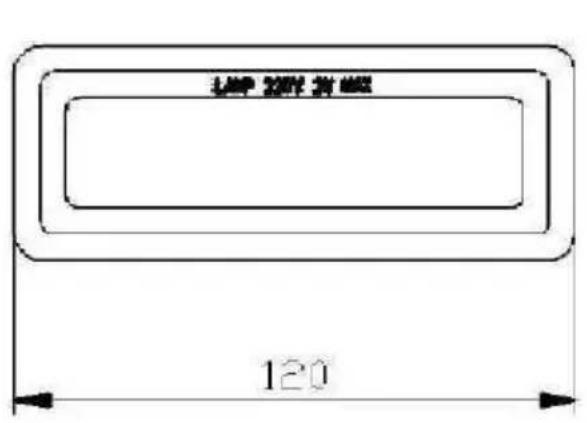
Unit:mm
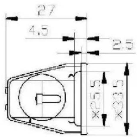
- Hood casing
- Exhaust outlet / check valve
natural_image
Technical line drawing of a mechanical component with labeled parts (1 and 2), no readable text or symbols beyond labels| Index | Description | Illustration | Quantity |
| PL-1 | Hood casing | 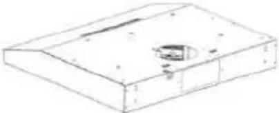 | 1 |
| PL-2 | Exit outlet/ Anti-return flag valve | 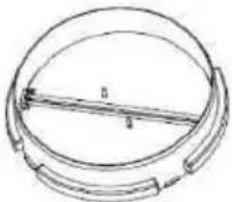 | 1 |
| PL-3 | Round lid | 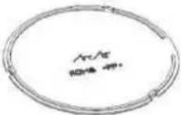 | 1 |
| PL-4 | Screws (ST4 * 30 mm) | 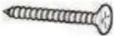 | 6 |
| PL-5 | Flat carbon filter |  | 2 |
Preparation before installation

ATTENTION
Carefully remove the carton. Wear gloves to protect your hands from sharp edges.

ATTENTION
Remove the protective film from the product before putting it into service.
Installation (Mode extraction)
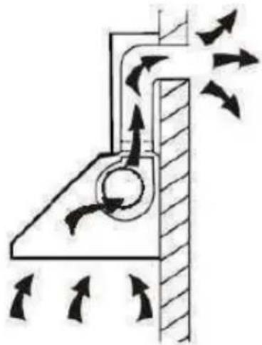
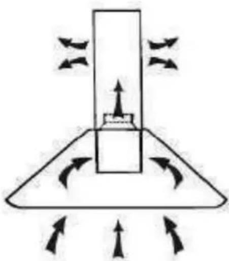
If the wall has an opening to the outside, your hood may be connected as shown in the diagram below
using the extraction duct provided or any suitable extraction conduit, for example a flexible aluminum sheath or constituted another non-flammable material with an inside diameter of less than 150mm.
natural_image
Diagram of airflow around a mechanical component with directional arrows indicating movement (no text or symbols)Installing the duct (not supplied)
• Determine the installation position exact of the hood.
- Plan the path of the air exhaust duct outward.
natural_image
Simple line drawing of a mechanical component with a cylindrical top and base (no text or symbols)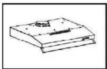
natural_image
Simple line drawing of a rectangular electronic device with a small protrusion on top (no text or symbols)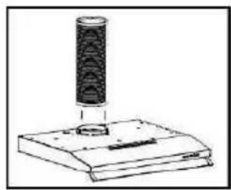
natural_image
Simple line drawing of a cylindrical object mounted on a base, with no visible text or symbols.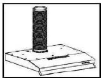
natural_image
Simple line drawing of a cylindrical object mounted on a base (no text or symbols)- Make sure that the duct path is as short and straight as possible. To allow optimal use, the duct must not exceed 2.50m long in total.
- The duct must lead directly to the outside, and must not lead to a attic, a house, a garage or in an enclosed space.
- Duct accessories (elbows, fittings and adapters) would reduce the flow of air.
- Bent elbows and S-shaped profiles do not provide efficient air extraction. They are not recommended for using.
Installation (Mode recycling)
If you do not have an exit to the outside, the exhaust duct is not required, and the installation procedures are same as
those described except that no extraction duct is to be installed..
natural_image
Diagram of a mechanical or fluid system with directional arrows and a central block, no text or symbols present.When charcoal filters are used, the suction power is decreased.
Recommendations for wall mounting
Do not make any changes to the unit or its mounting bracket on the wall!
Before installing the device, check the condition of the wall on which it will be fixed: the wall must be in good condition, it must not show any damage (cracks, sagging, humidity, ...).
Do not drill a hole near old holes, even plugged It is imperative that you consult a building professional to use the anchoring system (screws, dowels, etc.) appropriate to the material that constitutes your wall, as well as to the weight of the appliance. Observe the diameter of the fixing screws indicated in this manual.
Do not modify the holes for securing the unit or its mounting bracket to the wall.
Drill the wall with a drill of the appropriate size for the anchoring system. Remove debris and dust.
Regularly check the mounting points of the device on the wall. Tighten them if necessary.
Preparation before installation
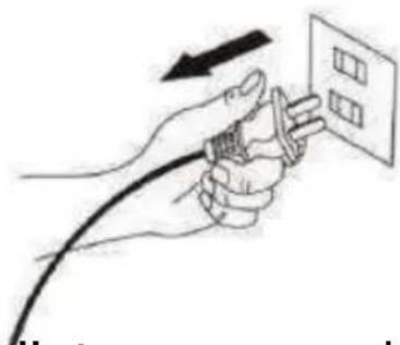
- Before installing, make sure the unit is not plugged into an electrical outlet.
- The following diagrams show the distances and holes to be drilled. The 2 suspension screws of the main unit must be mounted at a maximum of 820 mm above the firebox.
natural_image
Illustration of hands using a cable to hold an electrical outlet (no text or symbols)INSTALLATION (Fixing on wall)
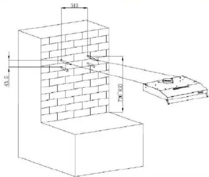
Determine the location of the hood cabinet. This must be installed at a maximum distance of 820 mm from the box table.
To fix it to the wall, drill 4 holes by placing them so that they correspond to the hole in the back of the hood. Insert plugs corresponding to the type of material of your wall in the holes.
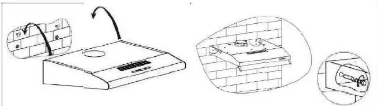
Screw the two screws ST4x 30 mm from the top and hang the hood.
Remove the two filters then attach the hood box to the wall with 2 other ST4x 30mm screws. Place the check valve on the hood.
INSTALLATION (Fixing under a cupboard)
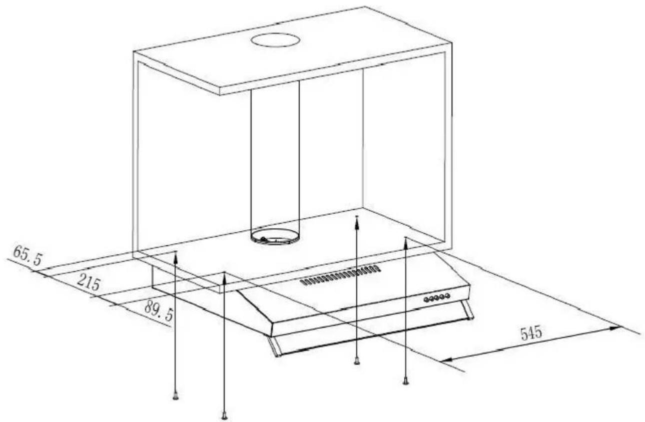
Place the one way valve on the hood.
Secure the hood to the cabinet with 4 screws
ST4x30 mm.
WARNING ! In extraction mode, fastening underneath a cabinet requires the use of an exhaust duct extending to the top of the cabinet.
In recycling mode, the exhaust grids on the front of the hood must not be covered.
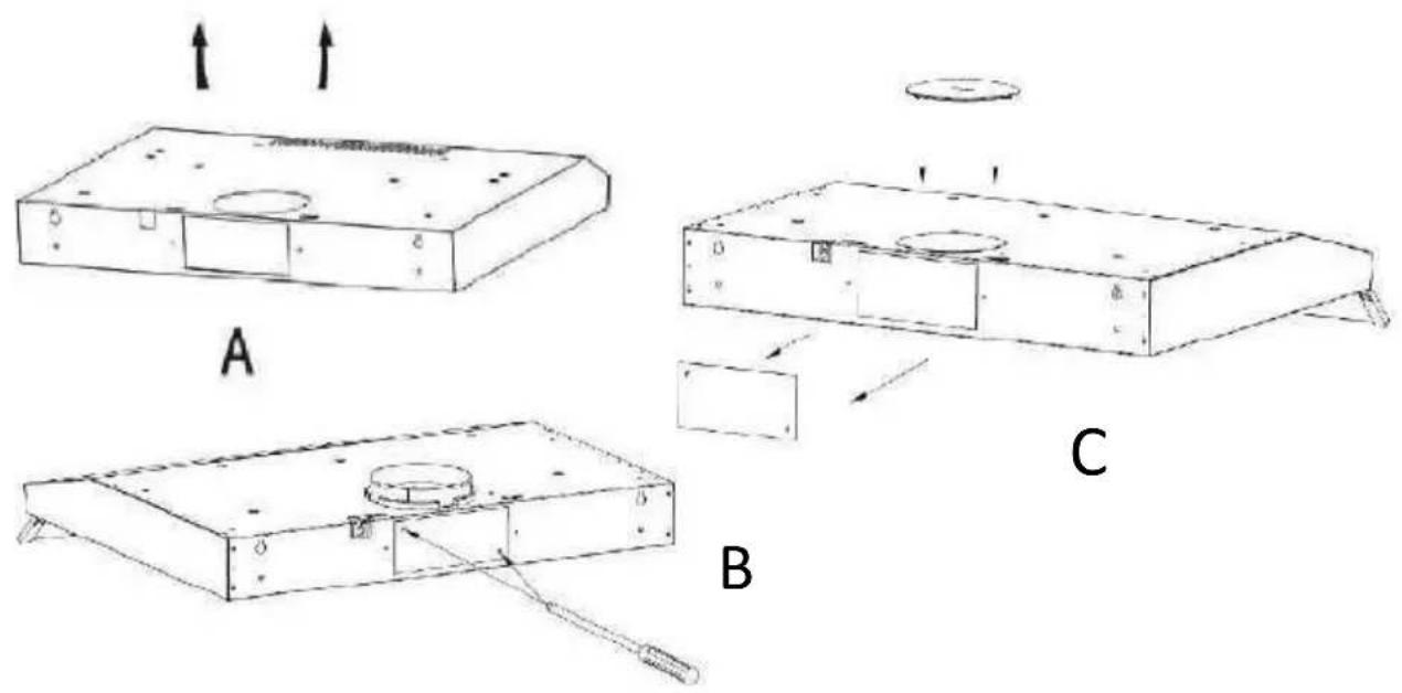
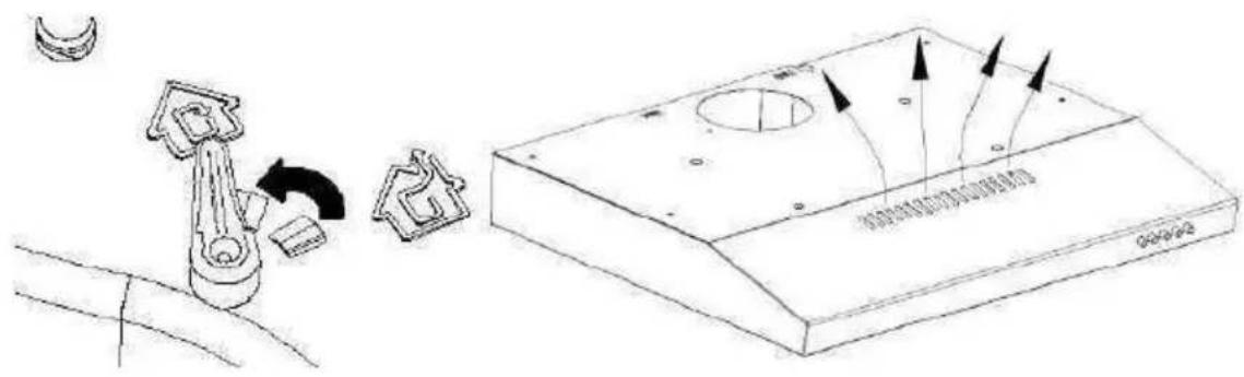
There are two modes of evacuation, horizontal evacuation and vertical evacuation. Please pay attention to the ventilation mode during installation.
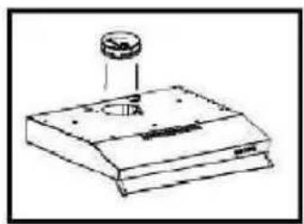
Vertical ventilation : See Pic A
Please use tool take out the round cover before using, and the air can be vented from top.
Horizontal ventilation : See Pic B and C.
Please use a tool to remove the rectangular cover before use, so that the air can be removed from the back. Cover the top drain with the round lid. The rectangular air outlet adapter for horizontal ventilation is not provided.
- Outdoor evacuation (mode extraction): Turn the adjuster to outdoor position, install the outlet, turn on the cooker hood, then the air will be vented from the outside outlet.
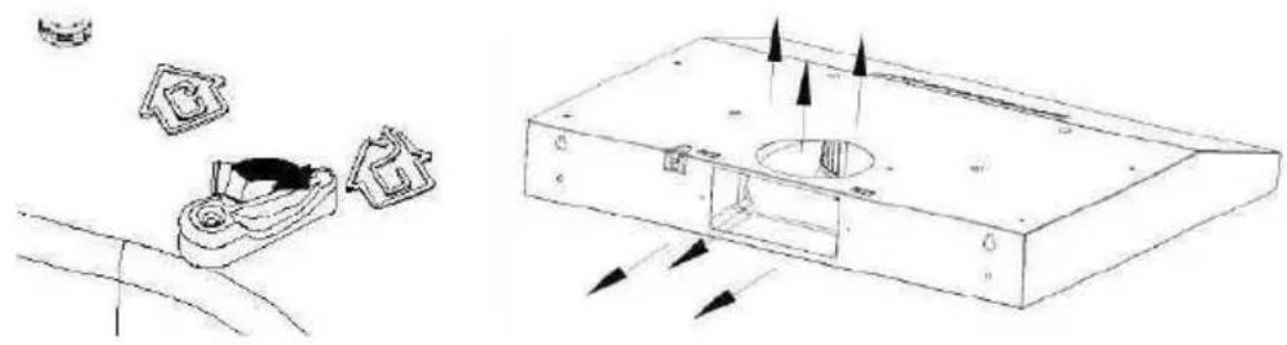
natural_image
Technical line drawing of a device with internal components and directional arrows indicating flow or movement (no text or symbols)- Internal evacuation (mode recycling): Turn the adjuster to inner position, install the rould lid. Turn on the hood, the air is exhausted through the interior exhaust outlet.
- The use of filters is necessary in this mode.
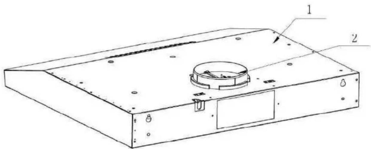
Replacement of the flat filter
(1) Remove the two grids
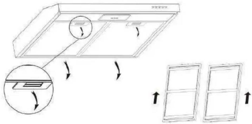
(2) Flip the grid
(3) Remove the fasteners and place the new carbon flat filter
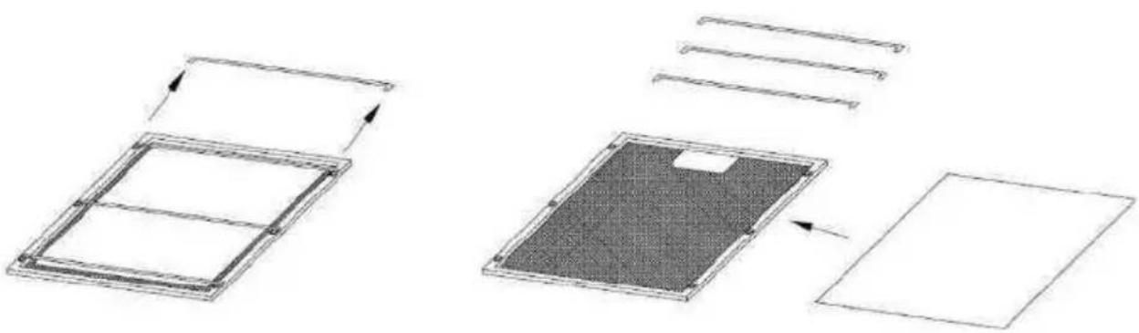
natural_image
Diagram showing two views of a rectangular panel with internal structure, one with arrows indicating direction (no text or symbols)- Note: The flat carbon filter is installed at the back of the rack and must be changed every three months
- Caution: The flat carbon filter can not be washed or recycled. It must be changed after 120 hours of use (minimum). The flat filter should not be exposed to heat.
Attention! Before cleaning switch the unit off and pull out the plug.
- Regular Cleaning
Use a soft cloth moistened with hand-warm mildly soapy water or household cleaning detergent. Never use metal pads, chemical, abrasive material or stiff brush to clean the unit.
• Monthly Cleaning for Grease Filter
ESSENTIAL: Clean the filter every month can prevent any risk of fire.
The filter collects grease, smoke and dust. This directly affects the efficiency of the cooker hood. If not cleaned, the grease residue (potential flammable) will saturate on the filter. Clean it with household cleaning detergent.
Control Panel Functions :
Motor stop button 0
Press this button to stop motor.
Low speed button
Press this button to operate the system at low speed.
Middle speed button

Press this button to operate the system at medium speed.
High speed button

Press this button to operate the system at high speed.
Lamp button

Press this button once to turn on the lights. Press again to turn off both lamps.
| Fault | Cause | Solution |
| Light on, but fan does not work | The fan blade is jammed. | Switch of the unit and repair by qualified service personnel only. |
| The motor is damaged. | ||
| Fan do not work | light burn | Replace the lamp with correct rating. |
| Power cord looses. | Plug in to the power supply again | |
| Serious Vibration of the unit | The fan blade is jammed. | Switch of the unit and repair by qualified service personnel only. |
| The fan motor is not fixed tightly. | Switch of the unit and repair by qualified service personnel only. | |
| The unit is not hung properly on the bracket. | Take down the unit and check whether the bracket is in proper location. | |
| Weak power | The filter is dirty | Clean the filter |
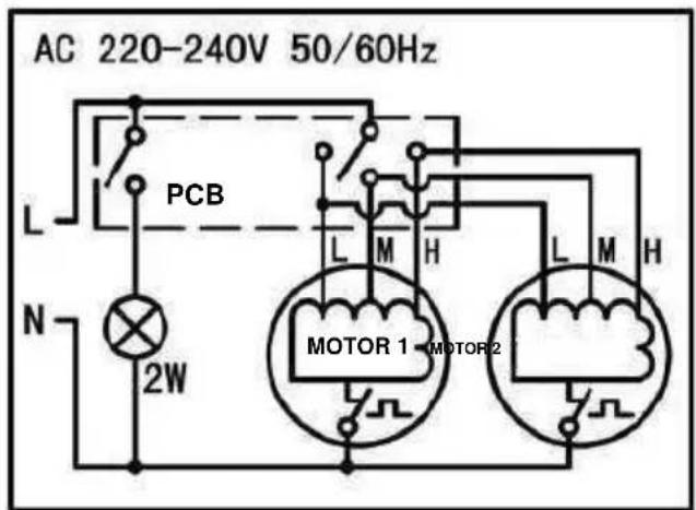
ELECTRICAL CONNECTION DIAGRAM
| Symbol | Value | Unit | |
| Model identification | OCEAHC440S9/ OCEAHC440B9/OCEAHC440W9(HJ2903L156) | ||
| Annual Energy Consumption | AEChotte | 73,4 | kWh/a |
| Energy Efficiency class | D | ||
| Time increase factor | f | 1,7 | |
| Fluid Dynamic Efficiency | FDEhotte | 9,0 | |
| Fluid Dynamic Efficiency class | E | ||
| Energy Efficiency Index | EEIhotte | 91,5 | |
| Measured air flow rate at best efficiency point | QBEP | 176,6 | m3/h |
| Measured air pressure at bestefficiency point | PBEP | 212 | Pa |
| Maximum airflow | Qmax | 332,4 | m3/h |
| Measured electric power input at best efficiency point | WBEP | 116,0 | W |
| Nominal power of the lighting system | WL | 2,0 | W |
| Average illumination of the lighting system on the cooking surface | Emoyen | 141 | lux |
| Lighting Efficiency | LEhotte | 70,5 | lux/W |
| Lighting efficiency class | A | ||
| Grease Filtering Efficiency | GFEhotte | 66,4 | |
| Grease Filtering Efficiency class | D | ||
| Measured power consumption offmode | Po | 0,00 | W |
| Sound power level | LWA | 71 | dB |
The method of measurement and calculation of the above table is in accordance with Commission Regulation (EU) No 65/2014 and 66/2014
OCEANIC
120-126 quai de Bacalan
CS11584
33000 Bordeaux
Importé par A.M.C.
123 quai Jules
Guesde 94400 Vitry
sur Seine
Note :
The following recommendations specify how to reduce the overall environmental impact of the cooking process.
(1) Install the range hood in a suitable location with good ventilation.
(2) Clean the cooker hood regularly so that nothing blocks the air.
(3) Do not forget to turn off the hood lamp once cooking is complete.
(4) Do not forget to turn off the range hood once cooking is complete.
Disassembly Information
Do not disassemble the unit in a manner that is not indicated in the operating instructions. This device must not be disassembled by the user. At the end of its life cycle, the appliance must not be disposed of with household waste. For recycling tips, please contact your local administration or dealer.
ENVIRONMENTAL PROTECTION
Electrical and electronic equipment is subject to selective collection.
Do not dispose of used electrical and electronic equipment with unsorted household waste; instead, take part in their selective collection.
It is for this reason that your appliance, as indicated by the symbol on its nameplate or on the packaging, must never be thrown in a public or private bin intended for household waste.
The user has the right to deposit the device in public collection places that selectively dispose of the waste to be recycled or reused for other applications. The packaging is recyclable..
natural_image
Pure electrical circuit lines without any symbolsoceanic
www.oceanic.eu
- oceanic
- Installation (Mode extraction)
- Installation (Mode recyclage)
- Contents
- IMPORTANT: Keep this guide for future reference.
- When using electrical appliances, basic safety precaution should always be followed, including the following:
- Electrical Shock Hazard
- Preparation before installation
- ATTENTION
- Installing the duct (not supplied)
- Installation (Mode recycling)
- Recommendations for wall mounting
- INSTALLATION (Fixing on wall)
- INSTALLATION (Fixing under a cupboard)
- Vertical ventilation : See Pic A
- Horizontal ventilation : See Pic B and C.
- Replacement of the flat filter
- Control Panel Functions :
- Importé par A.M.C.
- Note :
- Disassembly Information
- ENVIRONMENTAL PROTECTION
Brand : OCEANIC
Model : OCEAHC440S9
Category : Range hood