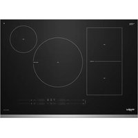
WCIT7530SS - Cooker WHIRLPOOL - Free user manual and instructions
Find the device manual for free WCIT7530SS WHIRLPOOL in PDF.


User questions about WCIT7530SS WHIRLPOOL
0 question about this device. Answer the ones you know or ask your own.
Ask a new question about this device
Download the instructions for your Cooker in PDF format for free! Find your manual WCIT7530SS - WHIRLPOOL and take your electronic device back in hand. On this page are published all the documents necessary for the use of your device. WCIT7530SS by WHIRLPOOL.
USER MANUAL WCIT7530SS WHIRLPOOL
30" AND 36" ELECTRIC INDUCTION COOKTOP OWNER'S MANUAL MANUEL D'UTILISATION DES TABLES DE CUISSON ÉLECTRIQUES À INDUCTION DE 30 PO ET 36 PO
Table of Contents/Table des matières
COOKTOP SAFETY ....2 Cooktop Safety ....2
COOKTOP MAINTENANCE AND CARE ....4 General Cleaning....4
WipeClean™ Cooktop Coating Cleaning Routine (on some models) 4
INSTALLATION REQUIREMENTS....4 Tools and Parts ....4
Location Requirements ....5
Electrical Requirements 7
INSTALLATION INSTRUCTIONS ....7 Prepare Location ....7
Install Brackets....8
Install Cooktop 9
Make Electrical Connection.... 10
Complete Installation 11
Your safety and the safety of others are very important.
We have provided many important safety messages in this manual and on your appliance. Always read and obey all safety messages.

This is the safety alert symbol.
This symbol alerts you to potential hazards that can kill or hurt you and others.
All safety messages will follow the safety alert symbol and either the word "DANGER" or "WARNING." These words mean:
DANGER
WARNING
You can be killed or seriously injured if you don't immediately follow instructions.
You can be killed or seriously injured if you don't follow instructions.
All safety messages will tell you what the potential hazard is, tell you how to reduce the chance of injury, and tell you what can happen if the instructions are not followed.
IMPORTANT SAFETY INSTRUCTIONS
WARNING: TO REDUCE THE RISK OF FIRE, ELECTRIC SHOCK, OR INJURY TO PERSONS, OBSERVE THE FOLLOWING:
■ Use this unit only in the manner intended by the manufacturer. If you have questions, contact the manufacturer.
■ WARNING: Danger of fire: Do not store items on the cooking surfaces. Never leave anything on the surface when unattended and not in use. Never place flammable or plastic items on or near the surface.
■ Before servicing or cleaning the unit, switch power off at service panel and lock the service disconnecting means to prevent power from being switched on accidentally. When the service disconnecting means cannot be locked, securely fasten a prominent warning device, such as a tag, to the service panel.
■ Installation work and electrical wiring must be done by qualified person(s) in accordance with all applicable codes and standards, including fire-rated construction.
■ Do not operate any fan with a damaged cord or plug. Discard fan or return to an authorized service facility for examination and/or repair.
■ Sufficient air is needed for proper combustion and exhausting of gases through the flue (chimney) of fuel burning equipment to prevent backdrafting. Follow the heating equipment manufacturer's guideline and safety standards such as those published by the National Fire Protection Association (NFPA), the American Society for Heating, Refrigeration and Air Conditioning Engineers (ASHRAE), and the local code authorities.
■ When cutting or drilling into wall or ceiling, do not damage electrical wiring and other hidden utilities.
■ Ducted fans must always be vented outdoors.
CAUTION: For general ventilating use only. Do not use to exhaust hazardous or explosive materials and vapors.
CAUTION: To reduce risk of fire and to properly exhaust air, be sure to duct air outside - do not vent exhaust air into spaces within walls or ceilings, attics or into crawl spaces, or garages.
WARNING: TO REDUCE THE RISK OF FIRE, USE ONLY METAL DUCTWORK.
WARNING: TO REDUCE THE RISK OF A COOKTOP TOP GREASE FIRE:
■ Never Leave Surface Units Unattended at Higher Heat Settings - Cooking oils and animal fats are flammable, boilover may cause smoking, and greasy spillovers may ignite.
■ Always turn hood ON when cooking at high heat or when flambeing food (i.e. Crepes Suzette, Cherries Jubilee, Peppercorn Beef Flambé).
■ Clean ventilating fans frequently. Grease should not be allowed to accumulate on fan or filter.
■ Use proper pan size. Always use cookware appropriate for the size of the surface element.
WARNING: TO REDUCE THE RISK OF INJURY TO PERSONS IN THE EVENT OF A COOKTOP TOP GREASE FIRE, OBSERVE THE FOLLOWING:
■ SMOTHER FLAMES with a close fitting lid, cookie sheet, or metal tray, then turn off the burner. BE CAREFUL TO PREVENT BURNS. If the flames do not go out immediately, EVACUATE AND CALL THE FIRE DEPARTMENT.
■ NEVER PICK UP A FLAMING PAN - you may be burned.
■ DO NOT USE WATER, including wet dishcloths or towels - a violent steam explosion will result.
■ Use an extinguisher ONLY if:
- You know you have a class ABC extinguisher, and you already know how to operate it.
- The fire is small and contained in the area where it started.
– The fire department is being called.
- You can fight the fire with your back to an exit.
Based on "Kitchen Fire Safety Tips" published by NFPA.
WARNING: To reduce the risk of fire or electrical shock, do not use this fan with any solid-state speed control device.
- Do Not Leave Children Alone – Children should not be left alone or unattended in area where appliance is in use. They should never be allowed to sit or stand on any part of the appliance.
■ Wear Proper Apparel – Loose-fitting or hanging garments should never be worn while using the appliance.
■ User Servicing – Do not repair or replace any part of the appliance unless specifically recommended in the manual. All other servicing should be referred to a qualified technician.
■ Use Only Dry Potholders – Moist or damp potholders on hot surfaces may result in burns from steam. Do not let potholder touch hot heating elements. Do not use a towel or other bulky cloth.
■ Utensil Handles Should Be Turned Inward and Not Extend Over Adjacent Surface Units – To reduce the risk of burns, ignition of flammable materials, and spillage due to unintentional contact with the utensil, the handle of a utensil should be positioned so that it is turned inward, and does not extend over adjacent surface units.
- Do Not Cook on Broken Cook-Top – If cook-top should break, cleaning solutions and spillovers may penetrate the broken cook-top and create a risk of electric shock. Contact a qualified technician immediately.
■ Do not place metallic objects such as knives, forks, spoons and lids on the cooktop surface since they can get hot.
CAUTION: Do not store items of interest to children in cabinets above a cooktop – children climbing on the cooktop to reach items could be seriously injured.
■ DO NOT TOUCH SURFACE UNITS OR AREAS NEAR UNITS – Surface units may be hot even though they are dark in color. Areas near surface units may become hot enough to cause burns. During and after use, do not touch, or let clothing or other flammable materials contact surface units or areas near units until they have had sufficient time to cool. Among these areas are (identification of areas – for example, the cook-top and surfaces facing the cook-top).
SAVE THESE INSTRUCTIONS
COOKTOP MAINTENANCE AND CARE
General Cleaning
IMPORTANT: Before cleaning, make sure all controls are off and the cooktop are cool. Always follow label instructions on cleaning products.
Soap, water, and a soft cloth or sponge are suggested first, unless otherwise noted.
STAINLESS STEEL (on some models)
NOTE: To avoid damage to stainless steel surfaces, do not use soap-filled scouring pads, abrasive cleaners, Cooktop Cleaner, steel-wool pads, gritty washcloths, or abrasive paper towels. Damage may occur to stainless steel surfaces, even with one-time or limited use.
Cleaning Method:
Rub in direction of grain to avoid damaging.
■ Affresh ^®† Stainless Steel Cleaner Part Number W10355016 (not included):
See the Quick Start Guide for contact information.
CERAMIC GLASS COOKTOP CLEANING
Cleaning Method:
- Ensure that the cooktop has cooled to room temperature.
- Cover food/residue with water for a minimum of 5 minutes. Ensure coverage over the entire affected area.
- Wipe with a non-abrasive sponge.
NOTE: If water dries or food/residue persists on the cooking surface, repeat Steps 2 and 3.
WipeClean™ Cooktop Coating Cleaning Routine (on some models)
IMPORTANT: Clean the cooktop according to these instructions after each use to avoid soil build ups and to prolong the life of your WipeClean™ Cooktop.
IMPORTANT: Cooktop scrapers may damage the coating and potentially diminish cleaning performance.
Everyday Cleaning:
-
Allow the cooktop to cool down completely before proceeding.
-
Spray the cooktop with water and soak for a minimum of 5 minutes, paying attention to cover the entire soiled area. For heavy stains, soak for 20-25 minutes.
-
Using a paper or kitchen towel remove the initial layer of soil from the surface.
-
Use a moist non-abrasive soft sponge and scrub the residual soil from the surface.
-
With a paper or kitchen towel wipe off and dry the surface.
-
Repeat steps 2 through 5 as necessary for stubborn soils.
Extremely Tough Soils:
- For extremely heavy soils, increase the amount of time soaking in water up to 45 minutes.
-
If an extremely tough soil persists, apply a few dime-sized drops of a non abrasive cooktop cleaner such as the affresh® Cooktop Cleaner to the affected areas to remove the remaining soil from the surface. Gently apply the cleaner with a paper towel.
■ Wipe away the cleaner with a warm damp cloth after using any detergent
■ Use of a scraper is not recommended as it might cause potential cooktop scratches -
Important: Do not apply excessive pressure while using detergents and do not use coarse or abrasive sponges with them. Detergents containing aggressive particles may damage your cooktop.
Tips & Tricks
■ Detergents may contain abrasive particles or harsh chemicals: pay attention to detergent's type when cleaning and do not let them sit on the surface for more than 10 minutes. Avoid these items when it comes to cleaning your glass top stove:
• Steel wool and other scrubby, abrasive or course sponges
- Abrasive powder cleansers or abrasive detergents
- Chlorine bleach
- Rust remover
- Ammonia
• Glass window cleaners
■ Light discoloration on the surface may happen if not cleaning frequently and cooking for a long time or cooking over a soiled surface: they usually do not compromise cleanability and surface properties.
■ Soaking with water will give the best results on cleaning: longer soaking times will increase cleanability efficiency and result, preserving cooktop surface over time.
- Do not slide pots on the surface or use it as a cutting board. Small scratches on the surface may appear over normal use, as in standard glass, without compromising its performance.
■ Avoid soiling build up on the surface as it can damage your product surface. Clean the cooktop surface after every spill, this will help preserve the cooktop surface over time.
INSTALLATION REQUIREMENTS
Tools and Parts
Gather the required tools and parts before starting installation. Read and follow the instructions provided with any tools listed here.
Tools Needed
■ Tape measure ■ Marker or pencil
■ Flat-blade screwdriver ■ Pliers
■ Phillips head screwdriver ■ 1/4" drill bit
■ Hand or electric drill ■ Jigsaw
Level
Parts Supplied
■ Brackets (2)
■ #6 x 3/4" (1.9 cm) clamping screws (4)
■ #8 x 3/8" (9.5 mm) sheet metal screws (7 screws for 30" and 36" models)
Parts needed
■ A UL listed or CSA approved strain relief
■ UL listed wire connectors
■ A UL approved junction box or 240 V outlet
■ Cooktop Bracket Adhesive Kit Part Number W11279478 if installing the cooktop into a marble countertop. See the "Assistance or Service" section of the Quick Start Guide for information on ordering.
Check local codes. Check existing electrical supply. See "Electrical Requirements".
It is recommended that all electrical connections be made by a licensed, qualified electrical installer.
Location Requirements
Make sure you have everything needed for correct installation. It is the responsibility of the installer to comply with the installation clearances specified in these instructions.
IMPORTANT: Observe all governing codes and ordinances. When installing cooktop, use minimum dimensions given.
■ To eliminate the risk of burns or fire by reaching over the heated surface units, cabinet storage space located above the surface units should be avoided. If cabinet storage is to be provided, the risk can be reduced by installing a range hood that projects horizontally a minimum of 5" (12.7 cm) beyond the bottom of the cabinets.
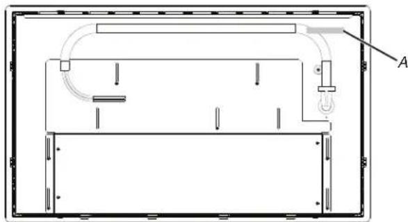
It is the installer's responsibility to comply with installation clearances specified on the model/serial/rating plate. The model/serial/rating plate is located on the underside of the cooktop burner box.
30" cooktop model/serial rating plate location

natural_image
Technical line drawing of a rectangular enclosure with internal components and labeled point A (no text or symbols beyond label)A. Model/serial/rating plate
36" cooktop model/serial rating plate location
natural_image
Technical line drawing of a mechanical or electrical component with no visible text, numbers, or symbols.A. Model/serial/rating plate
- Check the cooktop base for an approved installation label. Verify approved oven model numbers that can be installed with your cooktop model number. If you do not find this label, your cooktop may not be approved for use over an undercounter built-in oven. Contact your dealer to confirm that your cooktop is approved.
■ Ovens approved for this type of installation will have an approval label located on the top of the oven. If you do not find this label, contact your dealer to confirm that your oven is approved. Refer to oven manufacturer's Installation Instructions for approval for built-in undercounter use and proper cutout dimensions.
■ When installing cooktop over an undercounter built-in oven, do not fasten cooktop to countertop with clamps or seal cooktop to countertop. This will make the cooktop easier to remove if future servicing becomes necessary.
Use the countertop opening dimensions that are given with these Installation Instructions. Given dimensions are minimum clearances and provide 0" (0 cm) clearance.
■ Grounded electrical supply is required. See "Electrical Requirements" section.
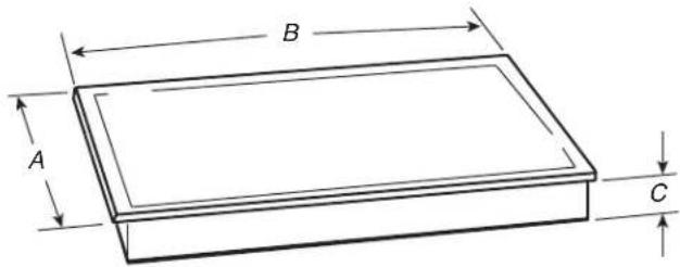
Product Dimensions
text_image
A B CModel A B C
| 30" | 21^5/_16 " (54.1 cm) | 30^13/_16 " (78.2 cm) | 3^3/_4 " (9.5 cm) |
| 36" | 21^5/_16 " (54.1 cm) | 36^5/_16 " (92.2 cm) | 3^3/_4 " (9.5 cm) |
With frame:
| Model A B C | ||||
| 30" | KitchenAid | 21^11/_16" (55.1 cm) | 31^3/_16" (79.2 cm) | 3^9/_16" (9.06 cm) |
| Whirlpool | 22"(55.9 cm) | 30^13/_16" (78.2 cm) | 3^5/_8" (9.2 cm) | |
| 36" | KitchenAid | 21^11/_16" (55.1 cm) | 36^11/_16" (93.2 cm) | 3^9/_16" (9.06 cm) |
| Whirlpool | 22"(55.9 cm) | 36^5/_16" (92.2 cm) | 3^5/_8" (9.2 cm) | |
NOTE: Maytag models do not have frames.
Cabinet Dimensions
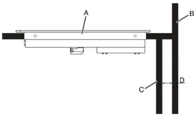
IMPORTANT: If installing a range hood or microwave hood combination above the range, follow the range hood or microwave hood combination installation instructions for dimensional clearances above the cooktop surface.
text_image
A B C DA. Cooktop
B. Rear wall
C. Cabinet back
D. 13/16" (2 cm) minimum clearance between house wall and cabinet back
text_image
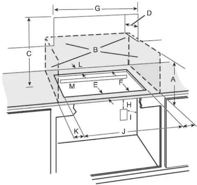
G D C B L M E F A H I K JA. For minimum clearance to top of cooktop, see NOTE*
B. Combustible area above countertop (shown by dashed box above)
C. 30" minimum clearance between top of cooktop platform and bottom of uncovered wood or metal cabinet (24" [61 cm] minimum clearance if bottom of wood or metal cabinet is covered by not less than 1/4" [6.4 mm] flame retardant millboard covered with not less than No. 28 MSG sheet steel, 0.015" [0.4 mm] stainless steel, or 0.024" [0.6 mm] aluminum or 0.020" [0.5 mm] copper)
D. 13" (33.0 cm) recommended upper cabinet depth
E. 2" (5.1 cm)
F. For details see the Table 1
G. 30" on 30" models, 36" on 36" models
H. Junction box or outlet; 12" (30.5 cm) minimum from bottom of countertop
I. Junction box or outlet; 10" (25.4 cm) from right-hand side of cabinet
J. For details see the Table 1
*NOTE: 18" (45.7 cm) minimum clearance from upper cabinet to countertop within minimum horizontal clearances to cooktop.
K. 1" (2.5 cm) minimum distance to nearest left and right side combustible surface above cooktop
L. 1" (2.5 cm) minimum clearance between back wall and countertop
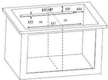
M. IMPORTANT: For proper ventilation, provide a vent cut out in the back of the cabinet per the following illustration. For standard and flush installation make sure the cut out and its cut out for ventilation have their center line aligned.
text_image
PEAP M2 M4 M3 = M1 =| Model | M1 | M2 | M2(Flush) | M3 | M4 |
| 30"4-zone | 13^11/_16" (34.7 cm) | 2^11/_16" (6.8 cm) | 2^15/_16" (7.4 cm) | 13/16"(2.1 cm) | 8^1/_8" (20.7 cm) |
| 30"5-zone | 22^5/_16" (56.7 cm) | 2^11/_16" (6.8 cm) | 2^15/_16" (7.4 cm) | 13/16"(2.1 cm) | 1^1/_2" (3.8 cm) |
| 36" | 23^3/_8" (59.4 cm) | 2^11/_16" (6.8 cm) | 2^15/_16" (7.4 cm) | 13/16"(2.1 cm) | 3^3/_16" (8.1 cm) |
Table 1
| CUTOUT | |||
| Dimension | 30" (4-zone) | 30" (5-zone) | 36" |
| F | 19 ^5/8 " (49.8 cm) | 20 ^7/16 " (51.9 cm) | 20 ^7/16 " (51.9 cm) |
| J | 28 ^1/2 " (72.4 cm) | 29 ^1/2 " (74.9 cm) | 33 ^1/16 " (84 cm) |
NOTE: After you make the countertop cutout, some installations may require notching down the base cabinet side walls to clear the cooktop base. To avoid this modification, use a base cabinet with sidewalls wider than the cutout.
If cabinet has a drawer, a 5/8" (13 cm) depth clearance from the countertop to the top of the drawer (or other obstruction) in base cabinet is required.
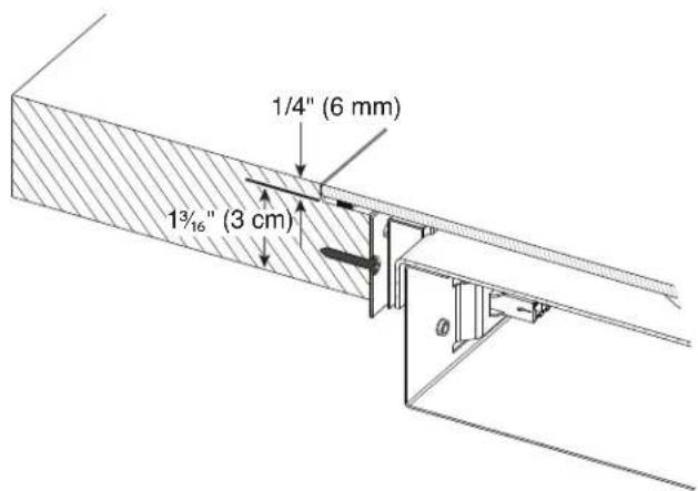
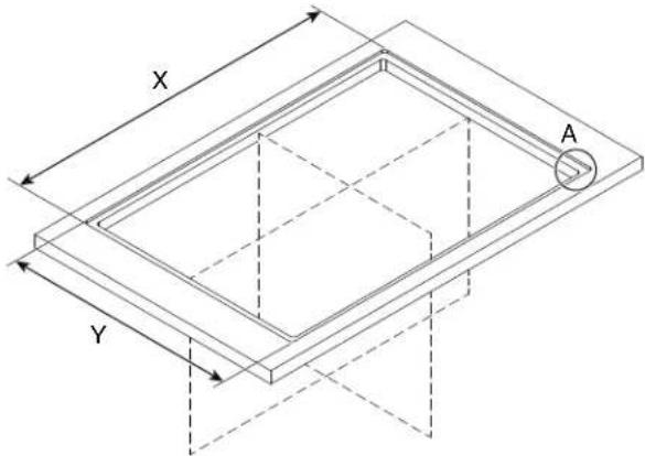
Flush Installation — Frameless
text_image
1/4" (6 mm) 13/16" (3 cm)| Model X | Y | |
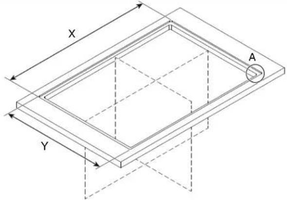
| 30" | 31" (78.7 cm) | 21 ^7 / _16 " (54.5 cm) |
| 36" | 36 ^1 / _2 " (92.7 cm) | 21 ^7 / _16 " (54.5 cm) |
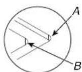
text_image
X A YDetail A
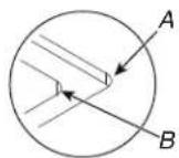
A. R14.7 ± 0.5 - For Whirlpool and Maytag, R8 ± 0.5 - For KitchenAid
B. R5.5 ± 0.5
Glass Radius (Whirlpool and Maytag) - 12.7 mm
Glass Radius (KitchenAid) - 6mm
Electrical Requirements
WARNING

Electrical Shock Hazard
Disconnect power before servicing.
Use 8 gauge copper wire.
Electrically ground cooktop.
Failure to follow these instructions can result in death, fire, or electrical shock.
If codes permit and a separate ground wire is used, it is recommended that a qualified electrical installer determine that the ground path and wire gauge are in accordance with local codes.
Check with a qualified electrical installer if you are not sure the cooktop is properly grounded.
It is not recommended to have a fuse in the neutral or ground circuit.
Make sure that the electrical connection and wire size are adequate and in conformance with the National Electrical Code, ANSI/NFPA 70-latest edition or CSA Standards C22.1-94, Canadian Electrical Code, Part 1 and C22.2 No.O-M91-latest edition, and all local codes and ordinances.
A copy of the above code standards can be obtained from:
National Fire Protection Association 1 Batterymarch Park Quincy, MA 02169-7471
CSA International
8501 East Pleasant Valley Road Cleveland, OH 44131-5575
Before You Make the Electrical Connection:
To properly install your cooktop, you must determine the type of electrical connection you will be using and follow the instructions provided for it here.
A 4-wire or 3-wire, single phase, electrical supply is required on a separate circuit as indicated by the tables below, fused on both sides of the line.
240 V, 60 Hz, AC only electrical supply:
| Cooktop Configuration Circuit | |
| 4 Cooking Zones 40 A | |
| 5 Cooking Zone 50 A | |
| 208 V, 60 Hz, AC only electrical supply: | |
| Cooktop Configuration Circuit | |
| 4 Cooking Zones | 40 A |
| 5 Cooking Zone 60 A | |
■ The cooktop should be connected directly to the junction box through flexible, armored or nonmetallic sheathed, copper cable. The flexible, armored cable extending from the fuse box or circuit breaker box should be connected directly to the junction box.
- Locate the junction box to allow as much slack as possible between the junction box and the cooktop so that the cooktop can be moved if servicing becomes necessary in the future.
■ Do not cut the conduit. The length of conduit provided is for serviceability of the cooktop.
■ A UL listed or CSA approved conduit connector must be provided at each end of the power supply cable (at the cooktop and at the junction box). A listed conduit connector is already provided at the cooktop.
If the house has aluminum wiring, follow the procedure below: Connect the aluminum wiring using special connectors and/or tools designed and UL listed for joining copper to aluminum.
Follow the electrical connector manufacturer's recommended procedure. Aluminum/copper connection must conform with local codes and industry accepted wiring practices.
INSTALLATION INSTRUCTIONS
Prepare Location
- Decide on the final location for the cooktop. NOTE: Countertop must be 116 " (3.0 cm) to 2" (5.1 cm) thick.
- If necessary, make cutout in countertop before installing cooktop. See "Location Requirements" section for more information.
- Clean cutout of any remaining dust and debris.
Install Brackets
NOTE: Cooktop Bracket Adhesive Kit Part Number W11279478 is required for installing the cooktop into a marble countertop. See the "Assistance or Service" section of the Quick Start Guide for information on ordering.
To Install Brackets into Marble Countertop:
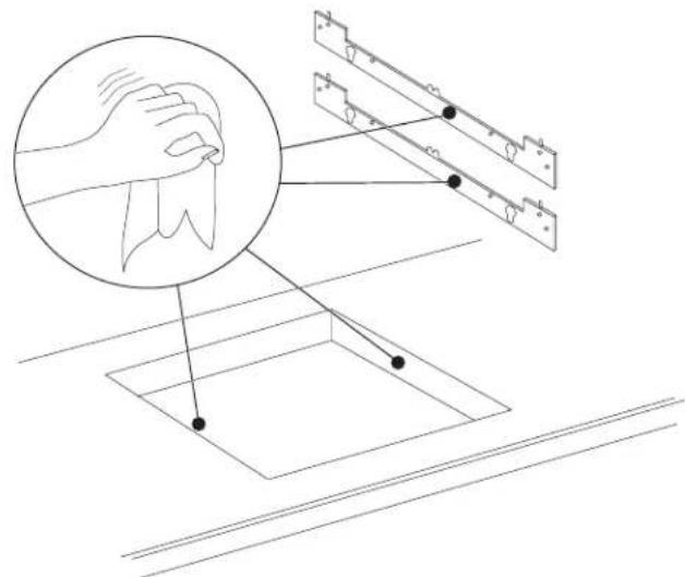
- Clean the brackets and cooktop cutout of any dust and debris.
text_image
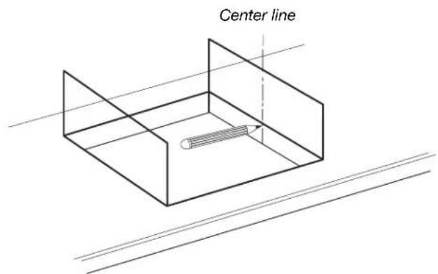
Technical diagram showing a hand gesture interacting with a mechanical assembly, with labeled components and alignment lines.- Measure the center line of the vertical sides of the cooktop cutout.
text_image
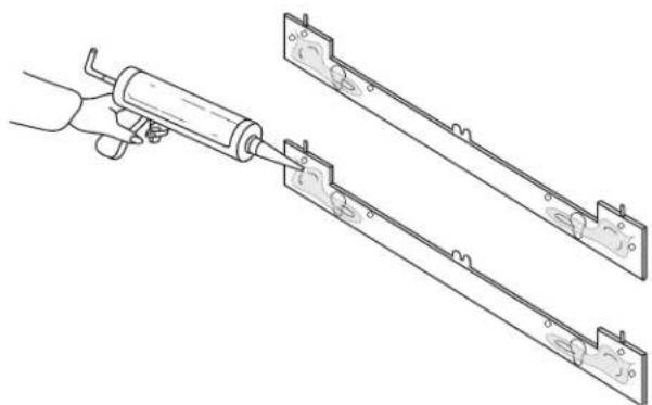
Center line- Apply the adhesive provided in the kit to the back side of the brackets.
natural_image
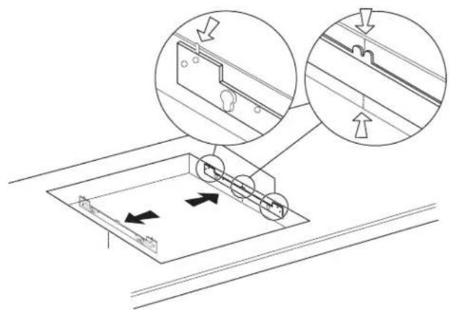
Line drawing of a hand holding a syringe connected to two parallel metal components (no text or symbols)- Position brackets in the center of the vertical centerline and is align the upper edge of the brackets so that they are flush with the countertop.
text_image
Technical diagram showing mechanical assembly with directional arrows and component placement, likely illustrating a rail or cable assembly.- Push the brackets firmly onto each side of the cooktop cutout and wait 1 hour for adhesive to dry.

natural_image
Line drawing of a mechanical setup with a circular dial and rectangular base (no text or symbols)To Install Brackets into Wood Countertop:
- Measure the center line of the vertical sides of the cooktop cutout.
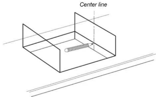
text_image
Center line-
Position brackets in the center of the vertical centerline and align the upper edge of the brackets so that they are flush with the countertop.
-
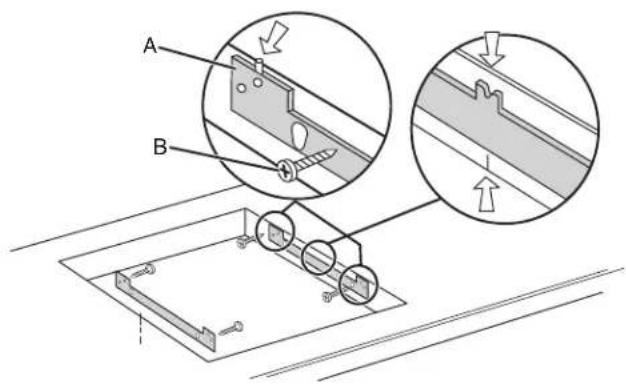
Attach the brackets in the cutout with the screws provided.
text_image
Technical diagram showing mechanical assembly with labeled parts A and B, including directional arrows indicating movement or force.A. Bracket
B. Screw
Install Cooktop
WARNING
Excessive Weight Hazard
Use two or more people to move and install or uninstall appliance.
Failure to do so can result in back or other injury.
- Using 2 or more people, place the cooktop upside down on a covered surface using the foam end posts from the packaging.
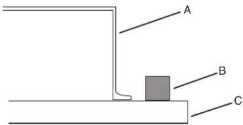
- Optional - Remove the foam roll from the package containing literature. Apply foam adhesive-side down around the bottom of the cooktop glass.
NOTE: The foam helps avoid damage to the underside of the cooktop glass from debris and helps the cooktop sit flat on uneven counters.
text_image
A B CA. Cooktop base
B. Foam
C. Assembly glass
- Lower the cooktop into the cutout with the back end of the cooktop angled down.
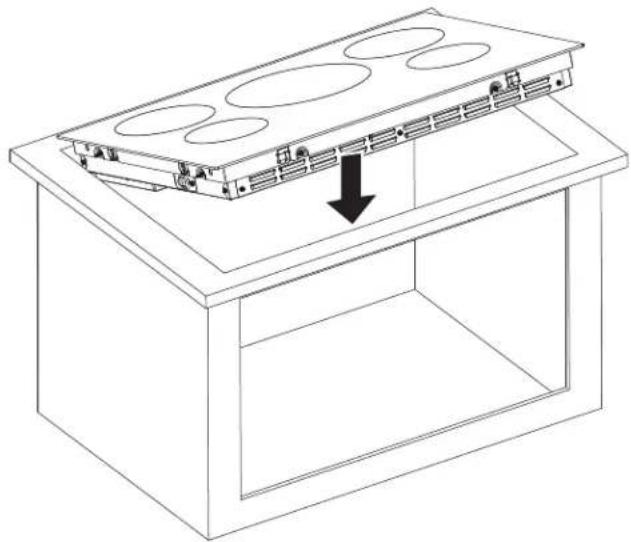
natural_image
Line drawing of a cabinet with internal components and a downward arrow indicating a component (no text or symbols)Front Side
- Make sure that the clips on each side of the cooktop line up with the brackets in the cutout.
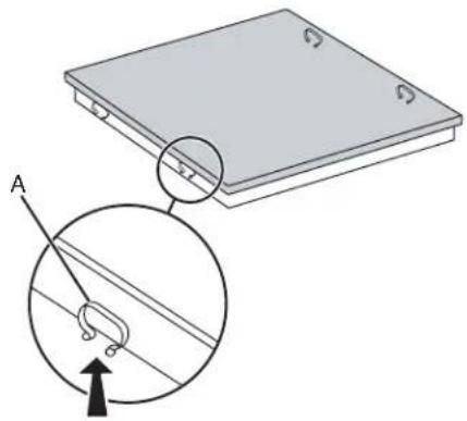
natural_image
Diagram showing a device with a magnified view of its internal structure (no text or symbols present)A. Clip
- Push down on cooktop to snap the cooktop clips onto the brackets installed in the cutout.
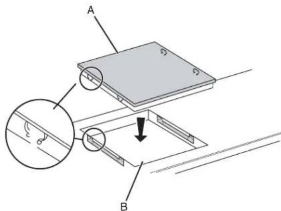
text_image
A BA. Induction cooktop
B. Cooktop cutout
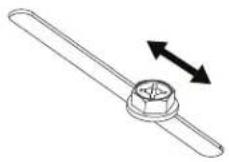
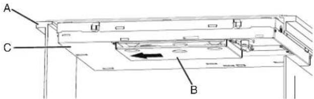
- On the underside of the cooktop, loosen only the 6 or 7 screws. See "Electrical Connection Options Chart" to complete for 30" and 36" models on the slider indicated in the image installation for your type of electrical connection.
below (Models with 4 cooking zones require 6 screws while models with 5 cooking zones require 7 screws).
Electrical Connection Options Chart
text_image
A C BA. Side of cabinet
B. Cooktop slider
C. Bottom side of cooktop
- Push the duct slider toward the side of the cabinet until the slider and cabinet touch.
- Tighten the screws on the slider.
Make Electrical Connection
WARNING

Electrical Shock Hazard
Disconnect power before servicing.
Use 8 gauge copper wire.
Electrically ground cooktop.
Failure to follow these instructions can result in death, fire, or electrical shock.
This cooktop is manufactured with a frame-connected, green bare) ground wire.
- Disconnect power.
- Remove junction box cover if it is present.
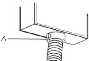
- Connect the flexible cable conduit from the cooktop to the junction box using a UL listed or CSA approved conduit connector.
natural_image
Technical line drawing of a mechanical assembly with a threaded component and labeled point A (no text or symbols beyond label)A. UL listed or CSA approved conduit connector
- Tighten screws on conduit connector if present.
If your home has: Go to section:
4-wire
4-Wire Cable from Home Power Supply
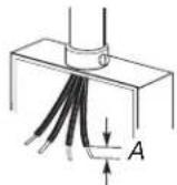
A. 1/2" (1.3 cm)
3-wire
3-Wire Cable from Home Power Supply
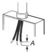
A. 1/2" (1.3 cm)
4-Wire Cable from Home Power Supply
IMPORTANT: Use the 4-wire cable from home power supply in the U.S.A where local codes do not allow grounding through neutral, New Branch circuit installations (1996 NEC), mobile homes and recreational vehicles, new construction, and in Canada.

text_image
A B C D E F G H II. UL listed or CSA approved conduit connector with wire bushing
A. Cable from home power supply
F. White wire (from home power supply)
B. Red wires
G. UL listed wire connector
C. Green (or bare) ground wires
H. Black wires
D. 3-wire cable from cooktop
E. Junction box
- Connect the 2 red wires (B) together using a UL listed wire connector.
- Connect the green (or bare) ground wire (C) from the cooktop cable to the green (or bare) ground wire (in the junction box) using a UL listed wire connector.
- Put a UL listed wire connector on the end of the white wire (F) NOTE: Do not connect the green (or bare) ground wire to the neutral (white) wire in the junction box.
- Connect the 2 black wires (H) together using a UL listed wire connector.
- Install junction box cover.
3-Wire Cable from Home Power Supply – U.S.A. Only
IMPORTANT: Use the 3-wire cable from home power supply where local codes permit a 3-wire connection.
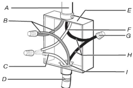
text_image
A B C D E F G H IA. Cable from home power supply
B. Red wires
C. Green (or bare) ground wires from cooktop
D. 3-wire cable from cooktop
E. Junction box
F. White wire (from home power supply)
G. UL listed wire connector
H. Black wires
I. UL listed or CSA approved conduit connector with wire bushing
- Connect the 2 red wires (B) together using a UL listed wire connector.
- Connect the green (or bare) cooktop cable wire (C) to the white (neutral) wire (F) in the junction box using a UL listed wire connector.
- Connect the 2 black wires (H) together using a UL listed wire connector.
- Install junction box cover.
Complete Installation
- Check that all parts are now installed. If there is an extra part, go back through the steps to see which step was skipped.
- Check that you have all your tools.
- Dispose of/recycle all packaging materials.
- Use a mild solution of liquid household cleaner and warm water to clean cooktop before use. Dry thoroughly with a soft cloth. For more information, see the "Cooktop Care" section of the Control Guide.
- Read "Cooktop Use" in the section of the Control Guide.
- Reconnect power.
NOTE: If the cooktop does not work after turning on the power, check that a circuit breaker has not tripped or a household fuse has not blown. See "Troubleshooting" section in the Control Guide for further information.
If you need Assistance or Service:
Please refer the "Assistance or Service" section of the Quick Start Guide or contact the dealer from whom you purchased your cooktop.
SÉCURITÉ DE LA TABLE DE CUISSON
natural_image
Technical line drawing of a rectangular enclosure with internal piping and ventilation ducts (no text or symbols)natural_image
Technical line drawing of a mechanical or electrical component with no visible text, numbers, or symbols.text_image
G D C B L M E F A H I K Jtext_image
1/4" (6 mm) 13/16" (3 cm)Modèle X Y
| 30 po 31 po (78,7 cm) 21 | 7/_16 po (54,5 cm) | |
| 36 po | 36^1/2 po (92,7 cm) | 21^7/_16 po (54,5 cm) |
text_image
X A YDétail A
National Fire Protection Association
1 Batterymarch Park
Quincy, MA 02169-7471
CSA International
8501 East Pleasant Valley Road
Cleveland, OH 44131-5575
Installation des supports
natural_image
Technical line drawing showing a hand holding a piece, with alignment lines and structural components (no text or symbols)natural_image
Line drawing of a hand holding a cylindrical tool with two parallel plates, no text or symbols presentnatural_image
Technical diagram showing mechanical assembly with arrows indicating motion, no text or symbols presentnatural_image
Line drawing of a mechanical setup with a circular dial and support structure (no text or symbols)text_image
Technical diagram showing mechanical assembly with labeled parts A and B, including directional arrows indicating movement or force.A. Support
B. Vis
natural_image
Line drawing of a mechanical assembly with circular components and an arrow indicating downward motion (no text or symbols)Avant
natural_image
Diagram showing a device with a magnified inset highlighting a cable or wire connection (no text or symbols present)A. Collier