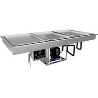
FTBP-2 - Ice machine Hatco - Free user manual and instructions
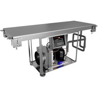
Find the device manual for free FTBP-2 Hatco in PDF.


| Product Type | Drop-In Frost Top Shelf Refrigerated Unit |
| Brand | Hatco |
| Model | FTBP-2 |
| Usage | Cold holding of pre-chilled foods (gastronorm pans) |
| Dimensions (L x D x H) | 991 mm x 735 mm x 437 mm (39" x 28-15/16" x 17-1/4") |
| Well dimensions (depth) | 90 mm (3-9/16") |
| Counter cutout (L x D) | 949 to 965 mm x 697 to 711 mm (37-3/8" to 38" x 27-7/16" to 28") |
| Shipping weight | 82 kg (180 lbs) |
| Power supply | 120 V, 345 W, 5.2 A, NEMA 5-15P (220-240 V available) |
| Refrigerant | R-290 (propane, flammable) |
| Ambient operating temperature | 18°C to 30°C (65°F to 86°F) |
| Temperature setting | Digital controller, adjustable in 1-2°C/°F increments, preset range of -4°C (25°F) |
| Defrost | Programmable automatic (disabled by default), 0 to 12 hour interval |
| Display | Digital, switchable °C/°F |
| Control panel | Remote, mountable on three sides, connected by 1219 mm (48") flexible conduit |
| Installation | Recessed into counter, requires enclosed cabinet with ventilation (961 cm² opening) |
| Drainage | NPSM 25 mm (1") drain connection for siphon or drain pan |
| Materials | Aluminized and stainless steel, copper evaporator coil |
| Daily cleaning | Mild detergent, non-abrasive cloth, disinfectant, no bleach or steel wool |
| Monthly cleaning (condenser) | Brushing or vacuuming condenser fins by qualified technician |
| Safety | Uses flammable refrigerant (R-290), requires adequate ventilation, turn off and unplug before maintenance |
| Spare parts | Contact a Hatco authorized distributor or after-sales service at +1-414-671-6350 |
| Warranty | 1 year parts and labor + 1 additional year parts (subject to registration) |
Frequently Asked Questions - FTBP-2 Hatco
User questions about FTBP-2 Hatco
0 question about this device. Answer the ones you know or ask your own.
Ask a new question about this device
Download the instructions for your Ice machine in PDF format for free! Find your manual FTBP-2 - Hatco and take your electronic device back in hand. On this page are published all the documents necessary for the use of your device. FTBP-2 by Hatco.
USER MANUAL FTBP-2 Hatco
Register Online! (see page 2)
FTBP and FTBP-S Series/Séries
natural_image
Technical line drawings of two identical electrical enclosure units with internal components and wiring (no text or symbols)WARNING
Do not operate this equipment unless you have read and understood the contents of this manual! Failure to follow the instructions contained in this manual may result in serious injury or death. This manual contains important safety information concerning the maintenance, use, and operation of this product. If you're unable to understand the contents of this manual, please bring it to the attention of your supervisor. Keep this manual in a safe location for future reference.
English = p 2
ADVERTENCIA
Important Owner Information....2
Introduction....2
Important Safety Information....3
Model Description 5
Model Designation 5
Specifications....6
Plug Configuration....6
Electrical Rating Chart....6
Refrigerant Information....6
Dimensions....7
Installation....7
General....7
Preparing the Installation Site 8
Installing the Unit....9
Countertop Cutout Dimensions 10
Installing the Remote Control Panel....10
Operation....11
General....11
Changing the Setpoint Temperature....12
Setting the Auto-Defrost Cycle(s)....12
Changing Fahrenheit and Celsius Setting....12
Maintenance....13
General....13
Daily Cleaning 13
Monthly Cleaning....13
Troubleshooting Guide....14
Options and Accessories 14
Limited Warranty 15
Authorized Parts Distributors ....Back Cover
IMPORTANT OWNER INFORMATION
Record the model number, serial number, voltage, and purchase date of the unit in the spaces below (specification label located on bottom of unit and back of control panel). Please have this information available when calling Hatco ^® for service assistance.
Model No. ____
Serial No.
Voltage
Date of Purchase
Register your unit!
Completing online warranty registration will prevent delay in obtaining warranty coverage. Access the Hatco website at www.hatcocorp.com, select the Support pull-down menu, and click on "Warranty".
Business
Hours: 7:00 AM to 5:00 PM Monday–Friday, Central Time (CT)
(Summer Hours — June to September:
7:00 AM to 5:00 PM Monday–Thursday
7:00 AM to 4:00 PM Friday)
Telephone: 414-671-6350
E-mail: support@hatcocorp.com
24 Hour 7 Day Parts and Service Assistance available in the United States and Canada by calling 414-671-6350.
Additional information can be found by visiting our web site at www.hatcocorp.com.
INTRODUCTION
Hatco Drop-In Frost Top Shelves are specially designed to hold quick-turnaround, cold foods such as pre-chilled beverages, snacks, hors d'oeuvres, and side dishes. The insulated, top-mount units are designed for full-size sheet pans and are available in 3/4, one, two, and three pan standard configurations as well as two and three pan slim configurations.
Hatco Drop-In Frost Top Shelves are a product of extensive research and field testing. The materials used were selected for maximum durability, attractive appearance, and optimum performance. Every unit is inspected and tested thoroughly prior to shipment.
This manual provides the installation, safety, and operating instructions for Drop-In Frost Top Shelves. Hatco recommends all installation, operating, and safety instructions appearing in this manual be read prior to installation or operation of a unit.
Safety information that appears in this manual is identified by the following signal word panels:
DANGER
DANGER indicates a hazardous situation which, if not avoided, will result in death or serious injury.
WARNING
WARNING indicates a hazardous situation which, if not avoided, could result in death or serious injury.
CAUTION
CAUTION indicates a hazardous situation which, if not avoided, could result in minor or moderate injury.
NOTICE
NOTICE is used to address practices not related to personal injury.

Read the following important safety information before using this equipment to avoid serious injury or death and to avoid damage to equipment or property.
DANGER
EXPLOSION HAZARD:
- Do NOT puncture refrigerant tubing. Use extreme caution and follow all local/regional codes for transportation or relocation of hydrocarbon equipment.
- Do NOT move or rotate condensing unit. Damage to refrigerant tubing will occur.
- Do not store or use gasoline or other flammable vapors and liquids in the vicinity of this equipment.
- Smoking is strictly prohibited near equipment with R-290 (hydrocarbon) refrigerant.
This unit uses flammable refrigerant. Follow handling instructions carefully in compliance with US and/or Canadian government regulations.
This unit must be installed in an isolated and sealed cabinet/partition only.
Do NOT use electrical appliances inside of the food storage compartments or inside the cabinet under the unit.
Do NOT use mechanical devices or any other means to accelerate the defrosting process. Follow the "Setting the Auto-Defrost Cycle" procedure in the OPERATION section in this manual to defrost ice buildup.
Keep the ventilation openings clear of obstructions at all times.
WARNING
ELECTRIC SHOCK HAZARD:
- Plug unit into a properly grounded electrical receptacle of the correct voltage, size, and plug configuration. If plug and receptacle do not match, contact a qualified electrician to determine and install proper voltage and size electrical receptacle.
- Turn OFF power switch and disconnect unit from power source before performing any cleaning, adjustments, or maintenance.
- DO NOT submerge or saturate with water. Unit is not waterproof. Do not operate if unit has been submerged or saturated with water.
- This unit is not "jet-proof" construction. Do not use jet-clean spray to clean this unit.
- Discontinue use if power cord is frayed or worn.
- Do not attempt to repair or replace a damaged power cord. Cord must be replaced by Hatco, an Authorized Hatco Service Agent, or a person with similar qualifications.
- This unit must be serviced by qualified personnel only. Service by unqualified personnel may lead to electric shock or burn.
- Use only Genuine Hatco Replacement Parts when service is required. Failure to use Genuine Hatco Replacement Parts will void all warranties and may subject operators of the equipment to hazardous electrical voltage, resulting in electrical shock or burn. Genuine Hatco Replacement Parts are specified to operate safely in the environments in which they are used. Some aftermarket or generic replacement parts do not have the characteristics that will allow them to operate safely in Hatco equipment.
WARNING
FIRE HAZARD:
• Install unit with a minimum of 7" (178 mm) of space between all sides of condensing unit and any combustible surfaces.
• Install unit in a cabinet enclosed on all four sides.
- All electrical receptacles must be at least 12" (305 mm) above the cabinet floor.
- Use caution and avoid hitting condensing unit hoses/lines when installing unit. Damage caused during installation is not covered under warranty.
- Condensing unit must be isolated from other electrical devices in the cabinet with fully sealed partitions.
- DO NOT use installation cabinet for storage of any items. Cabinet must be used only to keep condensing unit isolated from all other objects.
- To prevent damage to components, condensing unit should not be readily accessible to users/operators.
- This unit must be serviced by qualified personnel experienced with flammable refrigerant. Service by unqualified personnel may lead to fire or electric shock.
- Provide louvered or grill-style openings with a size of 12" x 12"/144 square inches (31 x 31 cm/961 square cm) in the cabinetry in front of and behind the condensing unit for proper ventilation. Failure to provide adequate air flow through the condensing unit may cause fire and/or unit failure and will void the unit warranty.
- Do not use flammable cleaning solutions to clean unit.
This unit must be installed by qualified, trained installers. Installation must conform to all local electrical and plumbing codes. Check with local plumbing and electrical inspectors for proper procedures and codes.
Make sure food product has been chilled to the proper food-safe temperature before placing in unit. Failure to chill food product properly may result in serious health risks. This unit is for holding pre-chilled food product only.
Hatco Corporation is not responsible for actual food product serving temperature. It is the responsibility of the user to ensure that food product is held and served at a safe temperature.
This unit is not intended for use by children or persons with reduced physical, sensory, or mental capabilities. Ensure proper supervision of children and keep them away from the unit.
Make sure all operators have been instructed on the safe and proper use of the unit.
Maintain proper cleanliness of the unit. Proper cleanliness and sanitation is critical for food-safe operation. Refer to the MAINTENANCE section for cleaning procedures.
Do not use mechanical devices or other means to accelerate the defrosting process.
This unit has no "user-serviceable" parts. If service is required on this unit, contact an Authorized Hatco Service Agent or contact the Hatco Service Department at 414-671-6350.
CAUTION
Locate unit at the proper counter height in an area that is convenient for use. Location should be level and strong enough to support weight of unit and contents.
Check for refrigerant leaks (using a certified hydrocarbon leak detector) before connecting or disconnecting power to equipment.
This unit requires adequate ventilation at all times during installation, operation and servicing.
NOTICE
This unit is designed for use in environments where the ambient temperature is between 65°F (18°C) (30°C).
For proper operation this unit must be installed with intake ducting. Failure to install properly will void warranty.
When shipped during cold weather months, store unit in proper ambient temperature environment for 10 hours to prevent compressor and/or refrigerant line damage. If unit is turned on and there is excessive noise and vibration, turn off immediately and allow additional warm up time.
Do not recirculate exhaust air inside cabinet when multiple refrigerated wells are installed together. Intake air should enter from outside of cabinet.
NOTICE
Transport and install unit in upright position only. Failure to do so may result in damage to the refrigeration system.
Use caution and avoid hitting condensing unit hoses/lines when installing unit. Damage caused during installation is not covered under warranty.
Do not locate unit in an area subject to excessive temperatures or grease from grills, fryers, etc. Excessive temperatures could cause damage to the unit.
Clean unit daily to avoid malfunctions and maintain sanitary operation.
Use non-abrasive cleaners and cloths only. Abrasive cleaners and cloths could scratch the finish of the unit, marring its appearance and making it susceptible to soil accumulation.
Do not use steel wool for cleaning. Steel wool will scratch the finish.
Do not use harsh chemicals such as bleach, cleaners containing bleach, or oven cleaners to clean the unit.
This unit is intended for commercial use only—NOT for household use.
All Models
Hatco® Drop-In Frost Top Shelves are reliable and versatile. Each unit has an insulated, stainless steel and aluminized steel housing. The bottom of the recessed frost top enclosure is covered with a copper evaporator coil to provide even cooling from edge to edge. A 1" NPSM drain in the recessed enclosure is standard on all units except the FTBP-3/4 and FTBP-1. Drop-In Frost Top Shelves are controlled by a digital temperature controller and a Power I/O (on/off) Switch housed in a single, remote-mountable control panel. The control panel is connected to the condensing unit with a 48" (1219 mm) power cord. A 6' (1829 mm) power cord and plug connected to the control panel provides power to the entire unit. All models are designed to be mounted to the topside of various types of countertop material including stainless steel, wood, Corian, Swanstone, etc... Hatco Drop-In Frost Top Shelves are designed, manufactured, and tested to maintain safe food holding temperatures.
The ecoization logo identifies products designed to reflect Hatco's commitment to improving, protecting, and preserving the global environment. Hatco refrigerated units qualify for the ecoization logo through the use of green-friendly insulation as well as a highly efficient hydrocarbon condensing unit.
FTBP-X Models
FTBP-X Models are available in 3/4, one, two, and three pan configurations. These models orient full-size sheet pans in the standard position with the short side facing the customer.
FTBP-SX Models
FTBP-SX Models are available in two and three pan configurations. These models are "slim" designed and orient full-size sheet pans with the long side facing the customer. The slim design allows easy, reachable access to everything on the frost top.
NOTE: Sheet Pans are available for the Drop-In Frost Top Shelves. Refer to the OPTIONS AND ACCESSORIES section in this manual for details.
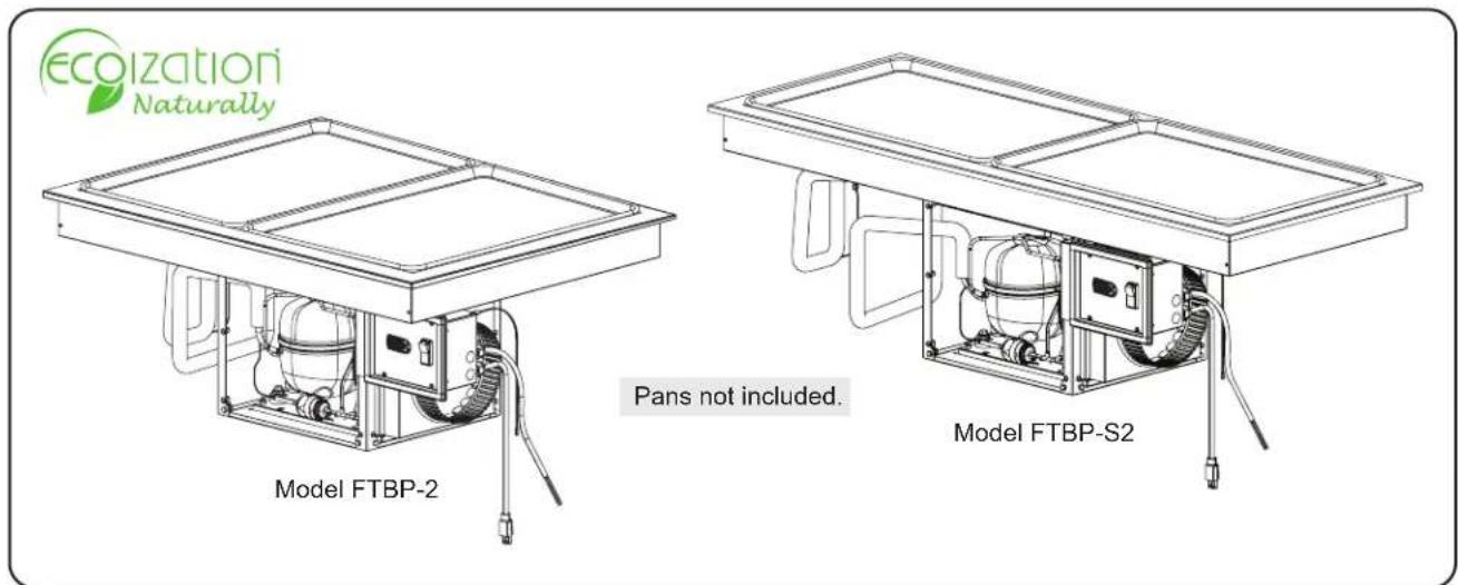
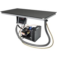
Drop-In Frost Top Shelves (Models FTBP-2 and FTBP-S2 shown)
MODEL DESIGNATION
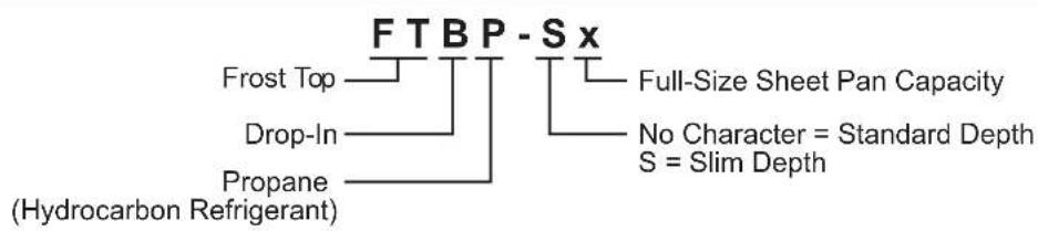
flowchart
graph TD
    A["FTBP-Sx"] --> B["Frost Top"]
    A --> C["Drop-In"]
    A --> D["Propane (Hydrocarbon Refrigerant)"]
    A --> E["Full-Size Sheet Pan Capacity"]
    A --> F["No Character = Standard Depth S = Slim Depth"]
Plug Configuration
Units are supplied from the factory with an electrical cord and plug installed. Plugs are supplied according to the applications.
WARNING
ELECTRIC SHOCK HAZARD: Plug unit into a properly grounded electrical receptacle of the correct voltage, size, and plug configuration. If plug and receptacle do not match, contact a qualified electrician to determine and install proper voltage and size electrical receptacle.
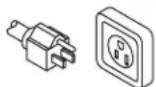
NEMA 5-15P
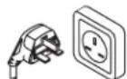
BS-1363
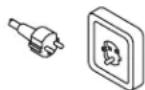
CEE 7/7 Schuko
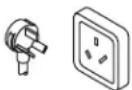
AS 3112
Plug Configuration
NOTE: Receptacle not supplied by Hatco®.
Electrical Rating Chart
| Model | Compressor Size Volts | Watts Amps | Plug Configuration | Shipping Weight | |
| FTBP-3/4 1 | 5 hp 120 V 345 W | 5.2 A NEMA 5 | -15P 120 lbs. (54 kg) | ||
| FTBP-1 | 1/5 hp 120 V | 345 W 5.2 A NEMA 5-15P | 132 lbs. (60 kg) | ||
| 1/3 hp 220/230/240 V 333/3 | 64/396 W 3.0/3.2 | 3.3 A BS-1363 | AS 3112, CEE 7/7 | ||
| FTBP-2 | 1/5 hp 120 V | 345 W 5.2 A NEMA 5-15P | 180 lbs. (82 kg) | ||
| 1/3 hp 220/230/240 V 333/3 | 64/396 W 3.0/3.2 | 3.3 A BS-1363 | AS 3112, CEE 7/7 | ||
| FTBP-3 | 1/5 hp 120 V | 345 W 5.2 A NEMA 5-15P | 213 lbs. (97 kg) | ||
| 1/3 hp 220/230/240 V 333/3 | 64/396 W 3.0/3.2 | 3.3 A BS-1363 | AS 3112, CEE 7/7 | ||
| FTBP-S2 | 1/5 hp 120 V | 345 W 5.2 A NEMA 5-15P | 182 lbs. (83 kg) | ||
| 1/3 hp 220/230/240 V 333/3 | 64/396 W 3.0/3.2 | 3.3 A BS-1363 | AS 3112, CEE 7/7 | ||
| FTBP-S3 | 1/5 hp 120 V | 345 W 5.2 A NEMA 5-15P | 239 lbs. (109 kg) | ||
| 1/3 hp 220/230/240 V 333/3 | 64/396 W 3.0/3.2 | 3.3 A BS-1363 | AS 3112, CEE 7/7 |
The shaded areas contain electrical information for International models only.
NOTE: Shipping weight includes packaging.
NOTE: The specification labels are located on the bottom of the unit and the back of the control panel. See the label for the serial number and verification of unit electrical information.
Refrigerant Information
Refrigerated Drop-In Wells use R-290 refrigerant in the condenser unit.
Operating Specifications
Refer to the Service Manual for detailed specifications and service procedures. Contact Hatco Technical Service at 414-671-6350 or support@hatcocorp.com to request a Service Manual.
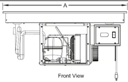
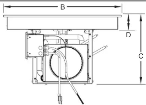
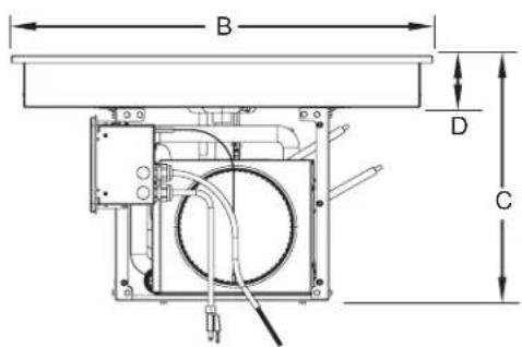
Dimensions — FTBP Models
| Model | Width (A) | Depth (B) | Overall Height (C) | Enclosure Height (D) |
| FTBP-3/4 | 21-1/16" (535 mm) | 18" (457 mm) | 23-11/16" (601 mm) | 3-9/16" (90 mm) |
| FTBP-1 | 21-1/16" (535 mm) | 28-15/16" (735 mm) | 23-11/16" (601 mm) | 3-9/16" (90 mm) |
| FTBP-2 | 39" (991 mm) | 28-15/16" (735 mm) | 17-1/8" (434 mm) | 3-9/16" (90 mm) |
| FTBP-3 | 57" (1448 mm) | 28-15/16" (735 mm) | 17-1/8" (434 mm) | 3-9/16" (90 mm) |
Dimensions — FTBP-S Models
| Model | Width (A) | Depth (B) | Overall Height (C) | Enclosure Height (D) |
| FTBP-S2 | 54-15/16" (1395 mm) | 21-1/16" (535 mm) | 17-1/8" (434 mm) | 3-9/16" (90 mm) |
| FTBP-S3 | 80-13/16" (2053 mm) | 21-1/16" (535 mm) | 17-1/8" (434 mm) | 3-9/16" (90 mm) |
Side View
INSTALLATION
General
Drop-In Frost Top Shelves are shipped from the factory completely assembled and ready for use. Use the following information and procedures to prepare the unit and installation site as well as to install the unit.
DANGER
EXPLOSION HAZARD:
- Do NOT puncture refrigerant tubing. Use extreme caution and follow all local/regional codes for transportation or relocation of Hydrocarbon equipment.
- Do NOT move or rotate condensing unit. Damage to refrigerant tubing will occur.
- Do not store or use gasoline or other flammable vapors and liquids in the vicinity of this equipment.
- Smoking is strictly prohibited near equipment with R-290 (hydrocarbon) refrigerant.
This unit uses flammable refrigerant. Follow handling instructions carefully in compliance with US and/or Canadian government regulations.
This unit must be installed in an isolated and sealed cabinet/partition only.
Do NOT use electrical appliances inside of the food storage compartments or inside the cabinet under the unit.
Do NOT use mechanical devices or any other means to accelerate the defrosting process. Follow the "Setting the Auto-Defrost Cycle" procedure in the OPERATION section in this manual to defrost ice buildup.
DANGER
Keep the ventilation openings clear of obstructions at all times.
WARNING
ELECTRIC SHOCK HAZARD:
- Plug unit into a properly grounded electrical receptacle of the correct voltage, size, and plug configuration. If plug and receptacle do not match, contact a qualified electrician to determine and install proper voltage and size electrical receptacle.
- Unit is not weatherproof. Locate unit indoors.
FIRE HAZARD:
- Install unit with a minimum of 7" (178 mm) of s; between all sides of condensing unit and any combustible surfaces.
- Provide louvered or grill-style openings with a size of 12" x 12"/144 square inches (31 x 31 cm/961 square cm) in the cabinetry in front of and behind the condensing unit for proper ventilation. Failure to provide adequate air flow through the condensing unit may cause fire and/or unit failure and will void the unit warranty.
- All electrical receptacles must be at least 12" (305 mm) above the cabinet floor.
This unit must be installed by qualified, trained installers. Installation must conform to all local electrical and plumbing codes. Check with local plumbing and electrical inspectors for proper procedures and codes.
CAUTION
Locate unit at the proper counter height in an area that is convenient for use. Location should be level and strong enough to support weight of unit and contents.
NOTICE
Transport and install unit in upright position only. Failure to do so may result in damage to the refrigeration system.
For proper operation this unit must be installed with intake ducting. Failure to install properly will void warranty.
When shipped during cold weather months, store unit in proper ambient temperature environment for 10 hours to prevent compressor and/or refrigerant line damage. If unit is turned on and there is excessive noise and vibration, turn off immediately and allow additional warm up time.
This unit is designed for use in environments where the ambient temperature is between 65°F (18°C) and 86°F (30°C).
Do not locate unit in an area subject to excessive temperatures or grease from grills, fryers, etc. Excessive temperatures could cause damage to the unit.
All Drop-In Frost Top Shelves are shipped in a shipping frame for protection and stability. Keep the unit in the shipping frame until the unit and the installation site are completely prepared for the unit to be installed.
-
Remove all external packaging from the unit.
-
Remove tape, protective packaging, and literature from all surfaces of unit.
NOTE: To prevent delay in obtaining warranty coverage, complete online warranty registration. See the IMPORTANT OWNER INFORMATION section for details.
Preparing the Installation Site
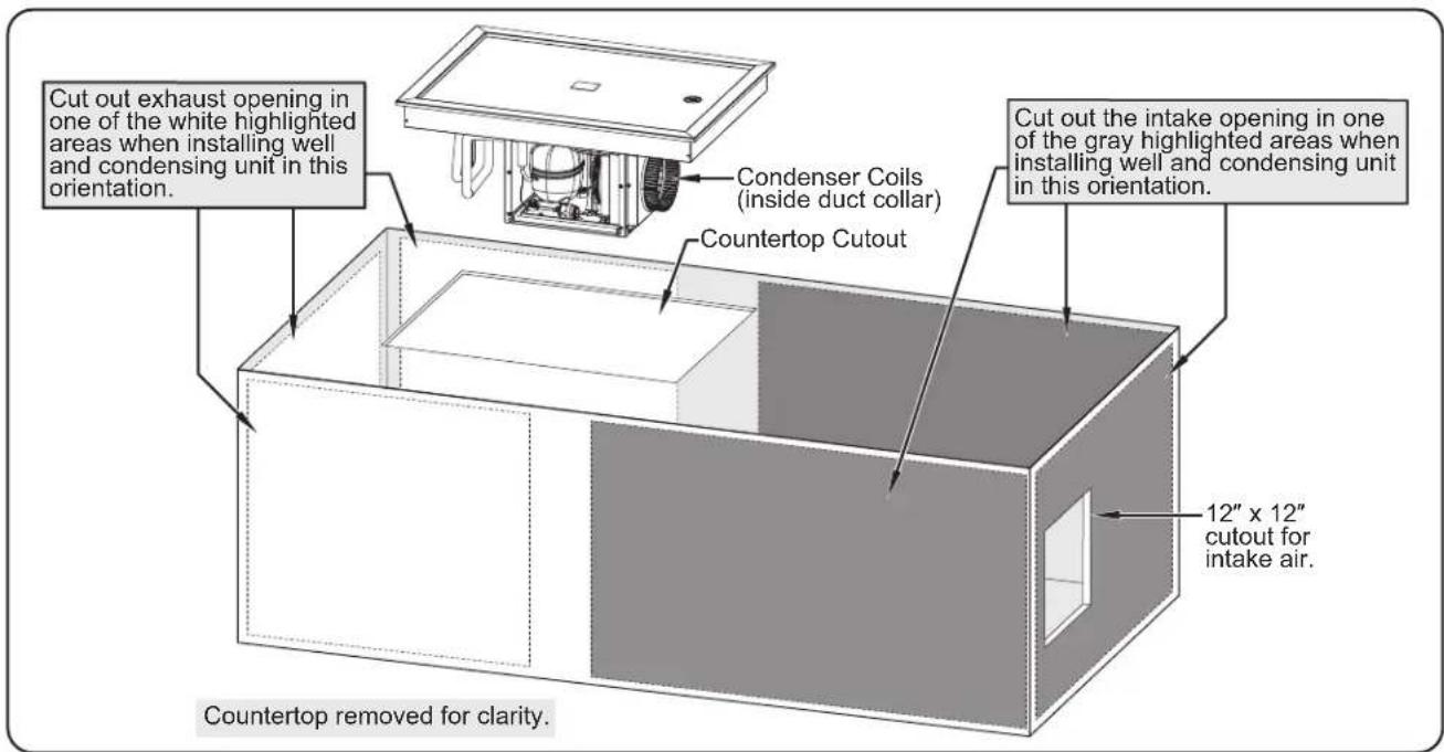
Survey the installation site. Take into account the need for louvered or grill-style openings in the cabinetry to provide proper ventilation for the unit as well as access to the control panel. One of these ventilation openings must be in front of the condensing coils with the other on the opposite side of the condensing coils. If multiple refrigerated wells are installed in the same counter, each unit must intake cool air and expel hot air.
NOTE: The condensing unit cannot be moved or rotated under the well. Damage to the refrigerant tubing will occur.
The cabinet must be enclosed on all four sides. The condensing unit must be isolated from other electronic devices using fully sealed partitions. The cabinet must allow access for ventilation, control access, and maintenance/cleaning access.
-
Cut the appropriate opening in the countertop for the unit being installed. Refer to "Countertop Cutout Dimensions" in this section.
-
If installing the control panel remotely, cut and drill the appropriate holes in the vertical surface where the control panel will be installed. Refer to the "Installing the Control Panel Remotely" procedure for cutout dimensions.
-
Cut opening in the cabinet for intake vent.
• The cutout must be 12" x 12" (31 x 31 cm).
- The opening for the intake must be no further than 5' (1524 mm) from the condenser coils.
- Cut opening in the cabinet for exhaust vent.
- The opening for the exhaust must be cut no more that 1" (25 mm) from cabinet floor.
- The opening should be a minimum of 12" x 12" (31 x 31 cm) or 144 square inches (961 square cm).
- The opening for the exhaust must be located on the opposite side of the condensing unit.
- Cut opening in the cabinet for access to the control panel, if necessary. Refer to the "Installing the Remote Control Panel" procedure for the cutout dimensions.
- Cut opening in the cabinet for access to the condensing unit coils for cleaning. Louvered or grill-style panels should be installed in the openings to protect the condensing unit.
- Make structural modifications or add bracing underneath the countertop to ensure the countertop will support the weight of the unit and its contents. Make sure a minimum 7" (178 mm) clearance will be available between the condensing unit and any interior surface.
NOTE: The countertop must be level to ensure proper draining of the frost top enclosure.
- Make sure a grounded electrical receptacle of the correct voltage, size, and plug configuration is within 6' (1829 mm) of the mounting location for the control panel. See the SPECIFICATIONS section for details.
WARNING
FIRE HAZARD: All electrical receptacles must be at least 12" (305 mm) above the cabinet floor.
Installing the Unit
NOTICE
Use caution and avoid hitting condensing unit hoses/lines when installing unit. Damage caused during installation is not covered under warranty.
- Lift the unit out of the shipping frame and carefully lower it into the countertop cutout. This step requires two or more people, depending on the unit.
- Apply NSF-approved silicone sealant around the edge of the unit to seal it to the countertop.
NOTE: If excessive condensation appears underneath the countertop during operation, apply polyurethane-based foam sealant in the gap between the underside of the countertop and the unit.
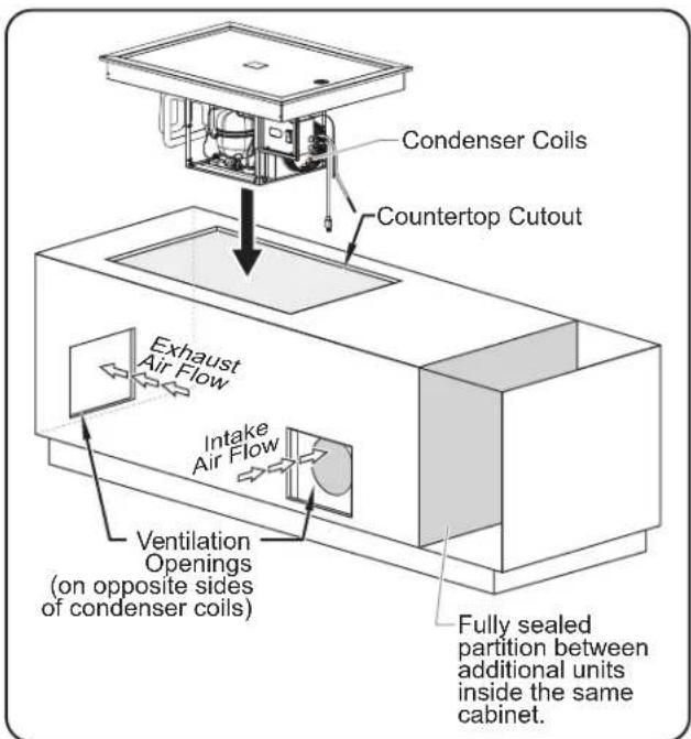
Installing a FTBP-2
WARNING
FIRE HAZARD:
• Install unit in a cabinet enclosed on all four sides.
- Use caution and avoid hitting condensing unit hoses/ lines when installing unit. Damage caused during installation is not covered under warranty.
- Condensing unit must be isolated from other electrical devices in the cabinet with fully sealed partitions.
- DO NOT use installation cabinet for storage of any items. Cabinet must be used only to keep condensing unit isolated from all other objects.
• To prevent damage to components, condensing unit should not be readily accessible to users/operators.
-
Install the control panel in the desired location.
-
The control panel can be installed on one of three sides of the condensing unit support frame. Do not install the control panel in front of the condenser coils.
- The control panel can be installed remotely within 48" (1219 mm) of the condensing unit. Refer to the "Installing the Control Panel Remotely" procedure in this section.
- Connect the 1" NPSM drain fitting to a trap and drain line (except FTBP-3/4 and -1 models). If a trap and drain line are not available, a catch pan (not supplied) must be used under the drain fitting to contain water draining from the frost top enclosure.
NOTE: Consult a qualified plumber for proper trap and drain installation that conforms to local plumbing codes.
- Install the intake air ducting.
a. Install the Intake Bracket to the inside of the cabinet over the 12"x12" cutout.
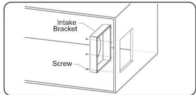
Installing the Intake Bracket
b. Install the flexible duct to the duct collar on the condensing unit using the duct clamp.
c. Install the duct collar on the other end of the flexible duct using the duct clamp.
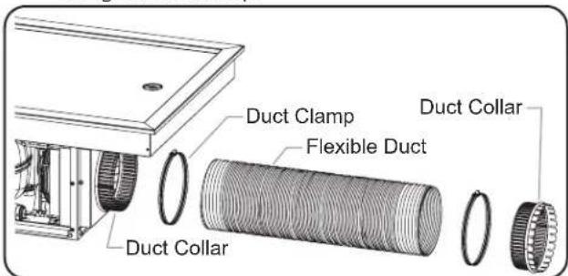
Installing the Flexible Duct
...continued
d. Insert the flexible duct into the intake bracket. Bend the tabs on the duct collar to the outside to secure the flexible duct.
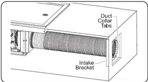
Installing the Flexible Duct to the Intake Bracket
- Clean the frost top enclosure thoroughly in preparation for initial operation. Refer to the MAINTENANCE section for proper cleaning procedures.
NOTE: If a catch pan is used underneath the drain fitting, make sure the pan is emptied regularly to prevent over-flowing. - Plug the unit into a properly grounded electrical receptacle of the correct voltage, size, and plug configuration. See the SPECIFICATIONS section for details.
Installing the Remote Control Panel
Use the following procedure to install the control panel remotely.
WARNING
Control panel must be mounted in a vertical surface. Mounting control panel in a horizontal surface may result in the collection of liquids and lead to electric shock.
-
Cut and drill the appropriate holes in the mounting surface. Refer to the "Control Panel Cutout and Screw Hole Dimensions" chart for the cutout dimensions.
-
Remove the four trim cover screws from the control panel and remove the trim cover.
- Position the control panel into the cutout opening through the backside.
- Fasten the control panel to the vertical surface using four screws (not supplied).
- Apply a 1/4" (6 mm) bead of NSF-approved silicone sealant where the trim cover will contact the cabinet surface. Refer to the "Control Panel Cutout and Screw Hole Dimensions" illustration for more information.
- Reinstall the trim cover on the control panel and secure in position using the four trim cover screws. Make sure to embed the trim cover edge into the silicone.
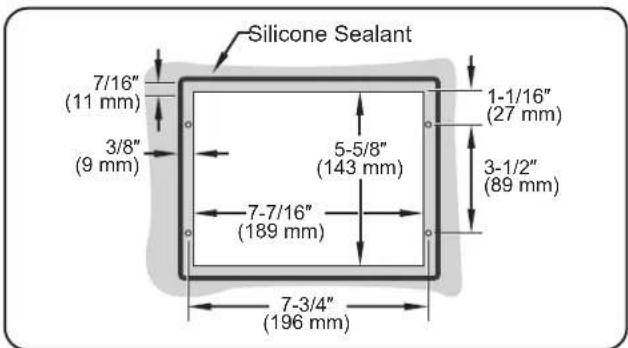
Control Panel Cutout and Screw Hole Dimensions
NOTE: Make sure the width of the control panel cutout does not exceed the above dimension.
Countertop Cutout Dimensions
| Model | Width (A) | Depth (B) |
| FTBP-3/4 | 19-7/16" to 20-1/8" (494 to 511 mm) | 16-1/2" to 17-1/16" (419 to 433 mm) |
| FTBP-1 | 19-7/16" to 20-1/8" (494 to 511 mm) | 27-1/2" to 28-1/2" (699 to 714 mm) |
| FTBP-2 | 37-3/8" to 38" (949 to 965 mm) | 27-5/16" to 28" (694 to 711 mm) |
| Model | Width (A) | Depth (B) |
| FTBP-3 | 55-3/8" to 56" (1407 to 1422 mm) | 27-5/16" to 28" (694 to 711 mm) |
| FTBP-S2 | 53-5/16" to 54" (1354 to 1372 mm) | 19-7/16" to 20-1/8" (494 to 511 mm) |
| FTBP-S3 | 79-3/16" to 79-7/8" (2011 to 2029 mm) | 19-7/16" to 20-1/8" (494 to 511 mm) |
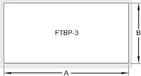
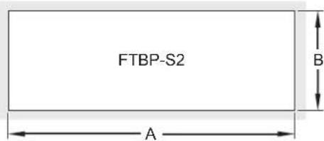
FTBP and FTBP-S Series Countertop Cutout Dimensions.
General
Use the following procedures to operate a Drop-In Frost Top Shelf.
WARNING
Read all safety messages in the Important Safety Information section before operating this equipment.
Make sure food product has been chilled to the proper food-safe temperature before placing in the unit. Failure to chill food product properly may result in serious health risks. This unit is for holding pre-chilled food product only.
FIRE HAZARD:
- DO NOT use installation cabinet for storage of any items. Cabinet must be used only to keep condensing unit isolated from all other objects.
- To prevent damage to components, condensing unit should not be readily accessible to users/operators.
NOTICE
When shipped during cold weather months, store unit in proper ambient temperature environment for 10 hours to prevent compressor and/or refrigerant line damage. If unit is turned on and there is excessive noise and vibration, turn off immediately and allow additional warm up time.
This unit is designed for use in environments where the ambient temperature is between 65°F (18°C) (30°C).
NOTE: If the display flashes "OFF" and then the current temperature, press and hold the key for three seconds. The display will no longer flash "OFF".
If the display flashes "df" and then the current temperature, press and hold the key for three seconds. The display will no longer flash "df".
Startup
- Move the Power I/O (on/off) Switch to the I (on) position (located on the control panel).
- The digital temperature controller will energize and "ON" will appear on the display, followed by the current temperature of the unit.
- The symbol on the display will illuminate to show the condensing unit is active and chilling the frost top.
NOTE: The unit is pre-set at the factory to a setpoint temperature of 25^ F ( -4^ C). If ambient conditions require adjustment to the setpoint temperature, refer to the “Changing the Setpoint Temperature” in this section.
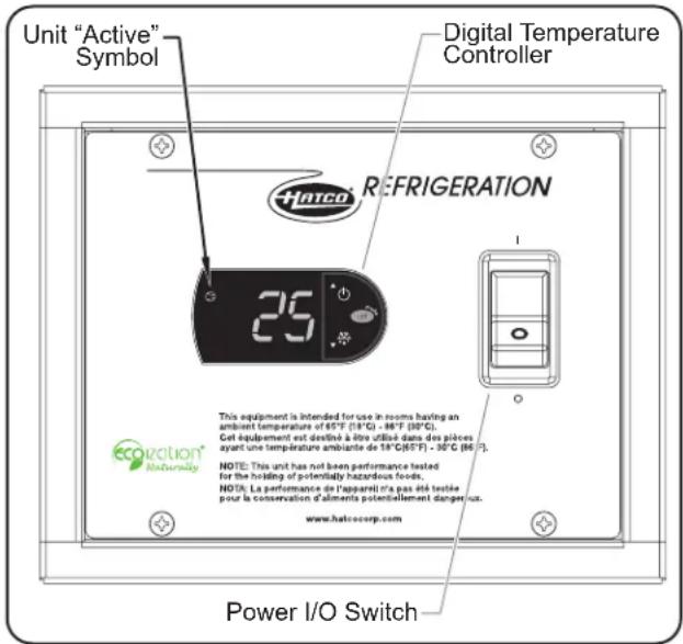
FTBP Series Control Panel
- Allow the unit approximately 30 minutes to reach the setpoint temperature before loading pre-chilled food product.
- Verify on the display that the unit has reached the proper setpoint temperature, and load the frost top with food pans that contain pre-chilled food product.
• Always use a food pan. Do not place food directly into the frost top.
- Stir thick food items frequently to keep food chilled uniformly.
WARNING
Hatco® Corporation is not responsible for the actual food product serving temperature. It is the responsibility of the user to ensure that the food product is held and served at a safe temperature.
Shutdown
- Move the Power I/O (on/off) Switch to the O (off) position. The digital temperature controller and condensing unit will shut off.
- Perform the "Daily Cleaning" procedure in the MAINTENANCE section of this manual.
NOTICE
Clean unit daily to avoid malfunctions and maintain sanitary operation.
NOTE: If a catch pan is used underneath the drain fitting, make sure the pan is emptied regularly to prevent overflowing.
Changing the Setpoint Temperature
Use the following procedure to change the setpoint temperature on the digital temperature controller.
NOTE: Changes to the setpoint temperature should be made in small increments (1 to 2 degrees). Wait at least two hours after a change in setpoint temperature before checking for the desired result.
- Press and hold the set by for one second until the display flashes the current setpoint temperature.
- Press the key to increase or decrease the setpoint temperature. If no key is pressed within 60 seconds, the display will revert to normal operation and the current temperature of the unit will be shown on the display.
- Press the key to lock in the new setpoint temperature. The display will revert to show the current temperature of the unit.
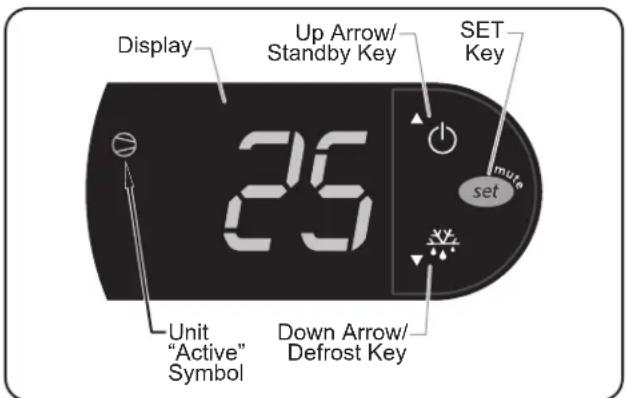
Digital Temperature Controller
NOTE: If the display flashes "OFF" and then the current temperature, press and hold the key for three seconds. The display will no longer flash "OFF".
If the display flashes "df" and then the current temperature, press and hold the key for three seconds. The display will no longer flash "df".
Setting the Auto-Defrost Cycle
Hatco® Refrigerated Wells are programmed at the factory with the auto-defrost cycle deactivated. Use the following procedure to activate the auto-defrost cycle if ambient or operational conditions require the unit to defrost occasionally. When the unit is in a defrost cycle, will appear on the display.
- Press and hold the 📂 for three seconds to access programming mode. "PS" (password) will appear on the display.
- Press the key again. A numeric value will appear on the display.
- Press the of key until the number "22" appears on the display, then press the key.
- Use the or key to scroll through the programmable parameters until "dl" (defrost interval) appears on the display.
-
Press the "dly" to select "dl". The current number of defrost cycles will be shown on the display. For new units, this value will be "0".
-
Press the ⏻ or ⚡ key within 60 seconds to scroll to the desired number of hours between defrost cycles. See below for examples of how the defrost cycle(s) operate:
"0" = auto-defrost is deactivated
“1” = unit will defrost every hour
"4" = unit will defrost every four hours
"12" = unit will defrost every twelve hours
If no key is pressed within 60 seconds, the display will revert to normal operation and the current temperature of the unit will be shown on the display.
-
Press the key to lock in the new defrost cycle setting.
-
Press and hold the set y for three seconds to exit programming mode. The display will revert to show the current temperature of the unit.
Changing Fahrenheit and Celsius Setting
Use the following procedure to change between Fahrenheit and Celsius on the display.
- Press and hold the “e” for three seconds to access programming mode. “PS” (password) will appear on the display.
- Press the key again. A numeric value will appear on the display.
- Press the of key until the number "22" appears on the display, then press the key.
- Use the or ⏻ key to scroll through the programmable parameters until rpears on the display.
- Press the key to select .
- Press the or key within 60 seconds to scroll to the desired setting. See below for the correct setting:
"0" = Displays Celsius
"1" = Displays Fahrenheit
If no key is pressed within 60 seconds, the display will revert to normal operation and the current temperature of the unit will be shown on the display.
- Press the key to lock in the new setting.
- Press and hold the suit for three seconds to exit programming mode. The display will revert to show the current temperature of the unit.
General
Hatco Drop-In Frost Top Shelves are designed for maximum durability and performance, with minimum maintenance.
WARNING
ELECTRIC SHOCK HAZARD:
- Turn OFF power switch and disconnect unit from power source before performing any cleaning, adjustments, or maintenance.
- DO NOT submerge or saturate with water. Unit is not waterproof. Do not operate if unit has been submerged or saturated with water.
FIRE HAZARD:
- Do not use flammable cleaning solutions to clean this unit.
- DO NOT use installation cabinet for storage of any items. Cabinet must be used only to keep condensing unit isolated from all other objects.
- To prevent damage to components, condensing unit should not be readily accessible to users/operators.
This unit has no "user-serviceable" parts. If service is required on this unit, contact an Authorized Hatco Service Agent or contact the Hatco Service Department at 414-671-6350.
NOTICE
Clean unit daily to avoid malfunctions and maintain sanitary operation.
Do not use steel wool for cleaning. Steel wool will scratch the finish.
Use non-abrasive cleaners and cloths only. Abrasive cleaners and cloths could scratch the finish of the unit, marring its appearance and making it susceptible to soil accumulation.
Do not use harsh chemicals such as bleach, cleaners containing bleach, or oven cleaners to clean this unit.
Daily Cleaning
- Move the Power I/O (on/off) Switch to the O (off) position and allow the unit to defrost.
NOTE: If a catch pan is used underneath the drain fitting, make sure the pan is emptied regularly to prevent overflowing.
- Remove and wash any pans.
- Clean the frost top using a damp cloth or sponge and mild detergent. Use a plastic scouring pad to remove any hardened food particles or mineral deposits.
- Wipe down the frost top with a non-abrasive, sanitized cloth to remove the detergent residue. Repeat until all detergent residue is gone and the frost top is clean.
- Wipe dry the entire unit using a non-abrasive, dry cloth.
- Wipe down the outside of the louvered or grill-style panels installed in the ventilation openings.
Monthly Cleaning
A refrigeration technician must perform the following procedure monthly to maintain proper and efficient operation of refrigerated units as well as prevent malfunction.
- Remove and clean both sides of the louvered or grill-style panels that are installed in the ventilation openings. Dirt and dust build-up in the panels can restrict air flow to the condensing unit and cause over-heating.
- Remove the duct from the duct collar.
- Remove the duct bracket for access to the condenser coil cooling fins.
a. Remove the two screws and tilt the duct bracket out of the groove.
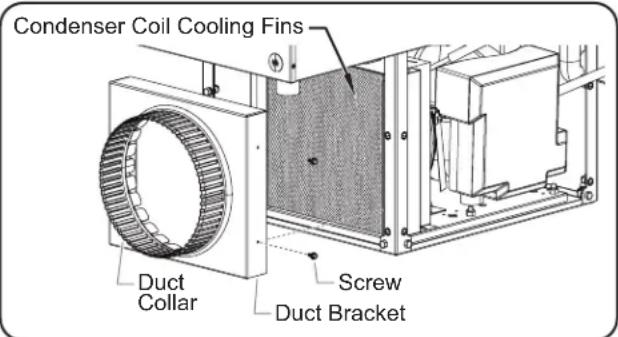
Removing the Duct Bracket
- Clean the condenser coil cooling fins. Dirt, dust, and lint build-up in the cooling fins will prevent proper cooling of the refrigerant in the refrigeration system. This buildup will cause inefficient operation and can lead to unit failure. Use the following methods to clean the condenser coil cooling fins:
• Vacuum the cooling fins.
- Brush the cooling fins vertically using a condenser coil brush. NOTICE: Use caution when brushing the cooling fins, they are delicate and can be bent easily. DO NOT use a wire brush.
NOTE: Depending on the conditions of the installation site, this cleaning procedure may need to be performed more often or less often than monthly. Monitor the level of dirt, dust, and lint buildup on the panels and cooling fins, and make adjustments to the frequency of cleanings as necessary.
WARNING
This unit must be serviced by qualified personnel only. Service by unqualified personnel may lead to electric shock or burn.
WARNING
ELECTRIC SHOCK HAZARD: Turn OFF power switch and disconnect unit from power source before performing any cleaning, adjustments, or maintenance.
| Symptom Probable | Cause Corrective Action | |
| Unit too cold. | Setpoint temperature too low. | Adjust the setpoint temperature to a higher setting. Refer to the “Changing the Setpoint Temperature” procedure in the OPERATION section. |
| Digital temperature controller not working properly. | Contact Authorized Service Agent or Hatco® for assistance. | |
| Unit not cold enough. Food product not pre-chilled before loading in unit. | Load unit with pre-chilled food product only. | |
| Setpoint temperature set too high. | ||
| Condenser coil and/or ventilation panels are plugged. | ||
| Too much frost built up inside of unit. | ||
| Digital temperature controller not working properly. | ||
| Refrigerant low/leaking or other internal condensing unit malfunction. | ||
| Unit makes excessive noise and vibration when turned on. | Internal components have not been adequately warmed before operation. | Turn off unit immediately. Unit should be stored in a warm environment of 65°F (18°C) for at least 10 hours. |
| Controller display flashes “OFF” and unit is not working. | The unit is in Standby mode. | Press and hold the▼key for three seconds. The display will no longer flash “OFF”. |
| Controller display flashes “df” and unit is not working. | The unit is in Defrost mode. | Press and hold the▼key for three seconds. The display will no longer flash “df”. |
| Unit plugged in, but not working. | Unit turned off. Turn on unit. | |
| Circuit breaker tripped. Reset circuit breaker. | if circuit breaker continues to trip, contact Authorized Service Agent or Hatco for assistance. | |
| Digital temperature controller not working properly. | Contact Authorized Service Agent or Hatco for assistance. | |
| Condensing unit overheated. | ||
| Internal condensing unit malfunction. | ||
Troubleshooting Questions?
If you continue to have problems resolving an issue, please contact the nearest Authorized Hatco Service Agency or Hatco for assistance. To locate the nearest Service Agency, log onto the Hatco website at www.hatcocorp.com, select the Support pull-down menu, and click on "Find A Service Agent"; or contact the Hatco Parts and Service Team at:
Telephone: 414-671-6350 e-mail: support@hatcocorp.com
OPTIONS AND ACCESSORIES
Food Pans
Accessory food pans are available in various sizes.
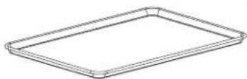
ALUM PAN....Half-size aluminum sheet pan — 18"W x 13"D (457 x 330 mm)
18"SHEET PAN ....Full size aluminum sheet pan — 18"W x 26"D (457 x 660 mm)

Food Pans
WARRANTY, EXCLUSIVE REMEDY:
Hatco Corporation (Seller) warrants that the products it manufactures (Products) will be free from defects in materials and workmanship under normal use and service and when stored, maintained, and installed in strict accordance with factory recommendations. Seller's sole obligation to the person or entity buying the Products directly from Seller (Customer) under this warranty is the repair or replacement by Seller or a Seller-authorized service agency, at Seller's option, of any Product or any part thereof deemed defective upon Seller's examination, for a period of: (i) the Warranty Duration from the date of shipment by Seller or (ii) the Warranty Duration from the date of Product registration in accordance with Seller's written instructions, whichever is later. The "Warranty Duration" shall mean the specific periods set forth below for specific Product components, or, to the extent not listed below, eighteen (18) months. Credit for Products or parts returned with the prior written permission of Seller will be subject to the terms shown on Seller's material return authorization form. PRODUCTS OR PARTS RETURNED WITHOUT PRIOR WRITTEN PERMISSION OF SELLER WILL NOT BE ACCEPTED FOR CREDIT. Expenses incurred by Customer in returning, replacing, or removing the Products will not be reimbursed by Seller. If the defect comes under the terms of the limited warranty, the Products will be repaired or replaced and returned to the Customer and the cost of return freight will be paid by Seller. The remedy of repair or replacement provided for herein is Customer's exclusive remedy. Any improper use, alteration, repairs, tampering, misapplication, improper installation, application of improper voltage, or any other action or inaction by Customer or others (including the use of any unauthorized service agency) that in Seller's sole judgment adversely affects the Product shall void this warranty. The warranty expressly provided herein may only be asserted by Customer and may not be asserted by Customer's customers or other users of the Products; provided, however, that if Customer is an authorized equipment dealer of Seller, Customer may assign the warranty herein to Customer's customers, subject to all of the limitations of these Terms, and in such case, the warranty shall be exclusively controlled by Seller in accordance with these Terms. THIS LIMITED WARRANTY IS EXCLUSIVE AND IS IN LIEU OF ANY OTHER WARRANTY, EXPRESSED OR IMPLIED, INCLUDING BUT NOT LIMITED TO ANY IMPLIED WARRANTY OF NONINFRINGEMENT, MERCHANTABILITY, OR FITNESS FOR A PARTICULAR PURPOSE, WHICH ARE EXPRESSLY DISCLAIMED.
One (1) Year Parts and Labor PLUS One (1) Additional Year Parts-Only Warranty:
Conveyor Toaster Elements (metal sheathed)
Drawer Warmer Elements (metal sheathed)
Drawer Warmer Drawer Rollers and Slides
Food Warmer Elements (metal sheathed)
Display Warmer Elements (metal sheathed air heating)
Holding Cabinet Elements (metal sheathed air heating)
Heated Well Elements — HW, HWB, and HWBI Series (metal sheathed)
Two (2) Year Parts and Labor Warranty:
Induction Ranges
Induction Warmers
One (1) Year Replacement Warranty:
TPT Pop-Up Toasters
One (1) Year Parts and Labor PLUS Four (4) Years
Parts-Only Warranty:
3CS and FR Tanks
One (1) Year Parts and Labor PLUS Nine (9) Years Parts-Only Warranty:
Electric Booster Heater Tanks
Gas Booster Heater Tanks
Ninety (90) Day Parts-Only Warranty:
Replacement Parts
Notwithstanding anything herein to the contrary, the limited warranty herein will not cover components in Seller's sole discretion such as, but not limited to, the following: coated incandescent light bulbs, fluorescent lights, heat lamp bulbs, coated halogen light bulbs, halogen heat lamp bulbs, xenon light bulbs, LED light tubes, glass components, and fuses; Product failure in booster tank, fin tube heat exchanger, or other water heating equipment caused by liming, sediment buildup, chemical attack, or freezing.
WARRANTY REGISTRATION INSTRUCTIONS:
Product registration must be submitted within 90 days from the date of shipment from our factory to qualify for additional coverage. Registration may be submitted through the form on Seller's website, through the form accessible through the QR code on the Product (where available), or by calling Customer Service with the required information at: 414-671-6350.
LIMITATION OF LIABILITY:
SELLER WILL NOT BE LIABLE FOR ANY INDIRECT, INCIDENTAL, CONSEQUENTIAL, PUNITIVE, EXEMPLARY, OR SPECIAL DAMAGES, INCLUDING WITHOUT LIMITATION ANY LOST PROFITS, COSTS OF SUBSTITUTE PRODUCTS, OR LABOR COSTS ARISING FROM THE SALE, USE, OR INSTALLATION OF THE PRODUCTS, FROM THE PRODUCTS BEING INCORPORATED INTO OR BECOMING A COMPONENT OF ANOTHER PRODUCT, OR FROM ANY OTHER CAUSE WHATSOEVER, WHETHER BASED ON WARRANTY (EXPRESSED OR IMPLIED) OR OTHERWISE BASED ON CONTRACT, TORT, OR ANY OTHER THEORY OF LIABILITY, AND REGARDLESS OF ANY ADVICE OR REPRESENTATIONS THAT MAY HAVE BEEN RENDERED BY SELLER CONCERNING THE SALE, USE, OR INSTALLATION OF THE PRODUCTS, EVEN IF SELLER IS AWARE OF THE POSSIBILITY OF SUCH DAMAGES. IN NO EVENT WILL SELLER'S AGGREGATE LIABILITY ARISING OUT OF OR RELATED TO THIS AGREEMENT EXCEED THE TOTAL AMOUNTS PAID TO SELLER BY CUSTOMER FOR THE PRODUCTS WITHIN THE THREE (3) MONTH PERIOD IMMEDIATELY PRECEDING THE EVENT GIVING RISE TO CUSTOMER'S CLAIM. THE LIMITATIONS SET FORTH HEREIN REGARDING SELLER'S LIABILITY SHALL BE VALID AND ENFORCEABLE NOTWITHSTANDING A FAILURE OF ESSENTIAL PURPOSE OF THE LIMITED REMEDY SPECIFIED IN THESE TERMS.
Seller reserves the right to update these Terms at any time, at its sole discretion, which become binding upon the date of publishing. For the most current version of our full Terms of Sale, see our website at: https://www.hatcocorp.com/terms-of-sale
natural_image
Technical line drawing of an industrial equipment enclosure with labeled dimension A (no text or symbols beyond label)Vue de face
Vue de côté
Généralités
Plateau aluminium demi (ALUM PAN)
natural_image
Simple line drawing of a rectangular tray or container (no text or symbols)Plateau aluminium ordinaire (18" SHEET PAN)
Bacs alimentaires
GARANTIE, RECOURS EXCLUSIF :
Byassee Equipment Co. Phoenix 602-252-0402
CALIFORNIA
Industrial Electric Commercial Parts & Service, Inc. Huntington Beach 714-379-7100
Chapman Appl. Service San Diego 619-298-7106
P & D Appliance Commercial Parts & Service, Inc. S. San Francisco 650-635-1900
COLORADO
Hawkins Commercial Appliance Englewood 303-781-5548
FLORIDA
Whaley Foodservice Repair Jacksonville 904-725-7800
Whaley Foodservice Repair Orlando 407-757-0851
B.G.S.I./Heritage Pompano Beach 954-971-0456
Comm. Appliance Service Tampa 813-663-0313
GEORGIA
Heritage Service Group Norcross 866-388-9837
HAWAII
Burney's Comm. Service, Inc. Honolulu 808-848-1466
Food Equip Parts & Service Honolulu 808-847-4871
ILLINOIS
Parts Town Addison 708-865-7278
Eichenauer Elec. Service Decatur 217-429-4229
Midwest Elec. Appl. Service Elmhurst 630-279-8000
Cone's Repair Service Moline 309-797-5323
IOWA
Goodwin Tucker Group Des Moines 515-262-9308
KENTUCKY
Tech 24 Lexington 859-254-8854
Tech 24 Louisville 502-451-5411
LOUISIANA
Chandlers Parts & Service Baton Rouge 225-272-6620
MARYLAND
Electric Motor Service Baltimore 410-467-8080
MASSACHUSETTS
Ace Service Co., Inc. Needham 781-449-4220
MICHIGAN
Bildons Appliance Service Detroit 248-478-3320
Commercial Kitchen Service Bay City 989-893-4561
Midwest Food Equip. Service Grandville 616-261-2000
MISSOURI
General Parts Kansas City 816-421-5400
Commercial Kitchen Services St. Louis 314-890-0700
Kaemmerlen Parts & Service St. Louis 314-535-2222
NEBRASKA
Anderson Electric Omaha 402-341-1414
NEVADA
Burney's Commercial Las Vegas 702-736-0006
Hi. Tech Commercial Service N. Las Vegas 702-649-4616
NEW JERSEY
Jay Hill Repair Fairfield 973-575-9145
Service Plus Flanders 973-691-6300
NEW YORK
Alpro Service Co. Maspeth 718-386-2515
Duffy's - AIS Buffalo 716-884-7425
3Wire Plattsburgh 800-634-5005
Duffy's - AIS Sauquoit 800-836-1014
J.B. Brady, Inc. Syracuse 315-422-9271
NORTH CAROLINA
Authorized Appliance Charlotte 704-377-4501
OHIO
Akron/Canton Comm. Svc. Inc. Akron 330-753-6634
Tech 24 Cincinnati 513-772-6600
Commercial Parts and Service Columbus 614-221-0057
Electrical Appl. Repair Service Brooklyn Heights 216-459-8700
E. A. Wichman Co. Toledo 419-385-9121
OKLAHOMA
Hagar Rest. Service, Inc. Oklahoma City 405-235-2184
OREGON
General Parts Group Portland 503-624-0890
PENNSYLVANIA
Elmer Schultz Services Philadelphia 215-627-5401
FAST Comm. Appl. Service Philadelphia 215-288-4800
AIS Commercial Parts and Service Pittsburgh 412-809-0244
K & D Service Co. Harrisburg 717-236-9039
Electric Repair Co. Reading 610-376-5444
RHODE ISLAND
Marshall Electric Co. Providence 401-331-1163
SOUTH CAROLINA
Whaley Foodservice Repair Lexington 803-996-9900
TENNESSEE
Camp Electric Memphis 901-527-7543
TEXAS
Armstrong Repair Service Houston 713-666-7100
Cooking Equipment Specialist Mesquite 972-686-6666
Commercial Kitchen Repair Co. San Antonio 210-735-2811
UTAH
La Monica's Rest. Equip. Service Murray 801-263-3221
VIRGINIA
Daubers Norfolk 757-855-4097
Daubers Springfield 703-866-3600
WASHINGTON
3Wire Seattle 800-207-3146
WISCONSIN
A.S.C., Inc. Madison 608-246-3160
A.S.C., Inc. Milwaukee 414-543-6460
CANADA
ALBERTA
Key Food Equipment Service Edmonton 780-438-1690
BRITISH COLUMBIA
Key Food Equipment Service Vancouver 604-433-4484
Key Food Equipment Service Victoria 250-920-4888
MANITOBA
Air Rite, Inc. Winnipeg 204-895-2300
NEW BRUNSWICK
EMR Services, Ltd. Moncton 506-855-4228
ONTARIO
R.G. Henderson Ltd. Toronto 416-422-5580
Choquette - CKS, Inc. Ottawa 613-739-8458
QUÉBEC
Choquette - CKS, Inc. Montreal 514-722-2000
Choquette - CKS, Inc. Québec City 418-681-3944
UNITED KINGDOM
Marren Group Northants +44(0)1933 665313
HATCO CORPORATION
P.O. Box 340500
Milwaukee, WI 53234-0500 U.S.A.
414-671-6350
support@hatcocorp.com
www.hatcocorp.com
Register your unit online!
See IMPORTANT OWNER INFORMATION section for details.


- WARNING
- ADVERTENCIA
- IMPORTANT OWNER INFORMATION
- Register your unit!
- INTRODUCTION
- DANGER
- CAUTION
- NOTICE
- Read the following important safety information before using this equipment to avoid serious injury or death and to avoid damage to equipment or property.
- EXPLOSION HAZARD:
- ELECTRIC SHOCK HAZARD:
- FIRE HAZARD:
- All Models
- FTBP-X Models
- FTBP-SX Models
- MODEL DESIGNATION
- Plug Configuration
- Refrigerant Information
- Operating Specifications
- INSTALLATION
- General
- Preparing the Installation Site
- Installing the Unit
- Installing the Remote Control Panel
- Startup
- Shutdown
- Changing the Setpoint Temperature
- Setting the Auto-Defrost Cycle
- Changing Fahrenheit and Celsius Setting
- Daily Cleaning
- Monthly Cleaning
- Troubleshooting Questions?
- OPTIONS AND ACCESSORIES
- Food Pans
- WARRANTY, EXCLUSIVE REMEDY:
- One (1) Year Parts and Labor PLUS One (1) Additional Year Parts-Only Warranty:
- Two (2) Year Parts and Labor Warranty:
- One (1) Year Replacement Warranty:
- One (1) Year Parts and Labor PLUS Four (4) Years
- Parts-Only Warranty:
- One (1) Year Parts and Labor PLUS Nine (9) Years Parts-Only Warranty:
- Ninety (90) Day Parts-Only Warranty:
- WARRANTY REGISTRATION INSTRUCTIONS:
- LIMITATION OF LIABILITY:
- Généralités
- GARANTIE, RECOURS EXCLUSIF :
- CALIFORNIA
- COLORADO
- FLORIDA
- GEORGIA
- HAWAII
- ILLINOIS
- IOWA
- KENTUCKY
- LOUISIANA
- MARYLAND
- MASSACHUSETTS
- MICHIGAN
- MISSOURI
- NEBRASKA
- NEVADA
- NEW JERSEY
- NEW YORK
- NORTH CAROLINA
- OHIO
- OKLAHOMA
- OREGON
- PENNSYLVANIA
- RHODE ISLAND
- SOUTH CAROLINA
- TENNESSEE
- TEXAS
- UTAH
- VIRGINIA
- WASHINGTON
- WISCONSIN
- CANADA
- ALBERTA
- BRITISH COLUMBIA
- MANITOBA
- NEW BRUNSWICK
- ONTARIO
- QUÉBEC
- UNITED KINGDOM
Brand : Hatco
Model : FTBP-2
Category : Ice machine