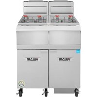
2VHG50AF - Deep fryer Vulcan - Free user manual and instructions
Find the device manual for free 2VHG50AF Vulcan in PDF.


| Product Type | Professional Gas Fryer |
| Brand | Vulcan |
| Model | 2VHG50AF (VHG Series) |
| Dimensions (width) | 34.3 cm (13-1/2 in) |
| Shortening Capacity | 20.4 to 22.7 kg (45-50 lb) |
| Number of Burners | 4 |
| Heat Output | 80,000 BTU/h |
| Gas Supply | Natural gas or propane (check nameplate) |
| Required Gas Pressure | Natural gas: 4 in WC (0.8 kPa) at outlet; propane: 10 in WC (2.75 kPa) |
| Incoming Pressure | Natural gas: 7-9 in WC; propane: 11-12 in WC |
| Electrical Connection | 120 V, three-prong grounded plug |
| Minimum Clearances | Sides: 15 cm (6 in); rear: 15 cm (6 in); open flame: 41 cm (16 in) |
| Main Functions | Frying, melting (liquid/solid), optional KleenScreen PLUS® filtration |
| Temperature Control | Solid-state control knob with digital display and empty test |
| Recommended Basket Capacity | 2.5 lb (1.1 kg) per basket (2 baskets included) |
| Included Accessories | Crumb catcher, basket hangers, brushes, twin baskets, manual |
| Safety | Overheat shutdown, empty test, thermal overload protection, gas valve |
| Daily Maintenance | Exterior cleaning with soapy water, oil filtration, filter cleaning |
| Boil-Out Procedure | Weekly or when changing oil, with degreaser and vinegar |
| Parts and Service | Authorized Vulcan service centers, parts available via customer service (800-814-2028) |
Frequently Asked Questions - 2VHG50AF Vulcan
User questions about 2VHG50AF Vulcan
0 question about this device. Answer the ones you know or ask your own.
Ask a new question about this device
Download the instructions for your Deep fryer in PDF format for free! Find your manual 2VHG50AF - Vulcan and take your electronic device back in hand. On this page are published all the documents necessary for the use of your device. 2VHG50AF by Vulcan.
USER MANUAL 2VHG50AF Vulcan
Model 1VHG75AF
TECHNICAL SERVICE AND PARTS ASSISTANCE: 1-800-814-2028
For additional information on Vulcan or to locate an authorized parts and service provider in your area, visit vulcanequipment.com.
Vulcan is a division of ITW Food Equipment Group | 3600 North Point Blvd., Baltimore, MD 21222
F-47679 REV. A (3-20)
IMPORTANT FOR YOUR SAFETY
THIS MANUAL HAS BEEN PREPARED FOR PERSONNEL QUALIFIED TO INSTALL GAS EQUIPMENT, WHO SHOULD PERFORM THE INITIAL FIELD START-UP AND ADJUSTMENTS OF THE EQUIPMENT COVERED BY THIS MANUAL.
POST IN A PROMINENT LOCATION THE INSTRUCTIONS TO BE FOLLOWED IN THE EVENT THE SMELL OF GAS IS DETECTED. THIS INFORMATION CAN BE OBTAINED FROM THE LOCAL GAS SUPPLIER.
IMPORTANT
IN THE EVENT A GAS ODOR IS DETECTED, SHUT DOWN UNITS AT THE MAIN SHUTOFF VALVE AND CONTACT THE LOCAL GAS COMPANY OR GAS SUPPLIER FOR SERVICE.
FOR YOUR SAFETY
DO NOT STORE OR USE GASOLINE OR OTHER FLAMMABLE VAPORS AND LIQUIDS IN THE VICINITY OF THIS OR ANY OTHER APPLIANCE.
WARNING
Improper installation, adjustment, alteration, service or maintenance can cause property damage, injury or death. Read the installation, operating and maintenance instructions thoroughly before installing or servicing this equipment.
IMPORTANT
IN THE EVENT OF A POWER FAILURE, DO NOT ATTEMPT TO OPERATE THIS DEVICE
TABLE OF CONTENTS
IMPORTANT FOR YOUR SAFETY.... 2
INTRODUCTION.... 4
GENERAL...... 4
ORDERING PARTS 4
UNPACKING.... 4
INSTALLATION.... 5
Clearances.... 5
Location 5
CODES AND STANDARDS.... 6
ASSEMBLY 7
FLUE CONNECTION....7
ELECTRICAL CONNECTION.... 7
GAS CONNECTION....8
Quick-Disconnect for Units on Casters....9
GAS PRESSURE 8
TEST GAS SUPPLY 8
FRYERS WITH CASTERS.... 8
LEVELING THE FRYER....9
OPERATION.... 10
FRYER CAPACITIES.... 10
OVER-TEMPERATURE SHUTDOWN.... 10
BEFORE FIRST USE.... 10
Cleaning....10
FILLING TANK WITH SHORTENING....11
BASIC FRYING INSTRUCTIONS.... 11
Fry Basket Guidelines.... 12
Fry Basket Capacity.... 12
EXTENDING SHORTENING LIFE....12
TURNING ON THE FRYER.... 12
BOIL OUT PROCEDURE....23
THERMAL OVERLOAD PROTECTION RESET BUTTON....24
MAINTENANCE.... 25
FLUE VENT INSPECTION.... 25
Service in the US and Canada 25
ERROR MESSAGES.... 25
TROUBLESHOOTING....26
Troubleshooting Chart.... 26
INTRODUCTION
GENERAL
Vulcan Fryers are produced with quality workmanship and material. Proper installation, usage and maintenance will result in years of satisfactory performance.
Before installing the fryer, thoroughly read this manual and carefully follow all instruction.
This manual is applicable to models listed on the cover page. Procedures in this manual will apply to all models unless specified. Pictures and illustrations can be of any model unless the picture or illustration needs to be model specific.
ORDERING PARTS
Customers may order parts directly from their local authorized service center. If not known, call Vulcan Technical Support at 800-814-2028.
To speed up your order, provide the model number, serial number, gas type, part needed, item part number (if known) and quantity needed.
UNPACKING
This fryer was carefully inspected before leaving the factory. The carrier assumes full responsibility for the safe delivery upon acceptance of the shipment. Check for possible shipping damage immediately after receipt.
If the fryer is found to be damaged, complete the following steps:
- Carrier must be notified within 5 business days of receipt.
- Carrier's local terminal must be notified immediately upon discovery (note time, date, and who was spoken to), and follow up and confirm with written or electronic communication.
- All original packing materials must be kept for inspection purposes.
- The fryer cannot have been moved, installed, or modified.
- Notify Vulcan Customer Service immediately at 800-814-2028.
Check that the following have been included:
- Crumb Rack(s)
♦ Basket Hanger(s)
♦ Tank Brush for Boil Out Procedure Only
Adjustable Casters (4) two locking, two non-locking for freestanding fryers. Fryer Batteries with the KleenScreen PLUS® Filtration System have casters installed from the factory. - Drain Pipe Extension for freestanding fryers only.
♦ Twin Fry Baskets (2) per fry tank - Cleanout Rod
Fryer Batteries with the KleenScreen PLUS® Filtration System - Filter Pan
VHG SERIES GAS FRYERS
- Suction Tube
- Screen Assembly
• High temperature discard hose - Crumb Basket
- Manual, Quick Start Guide(s), and Warranty-Keep in safe place for reference
INSTALLATION
Do not use the door or its handle to lift the fryer.
Before installing the fryer, verify that the type of gas (natural or propane) agrees with the specifications on the fryer data plate, which is located on the inside of the door panel. Make sure the fryer is configured for the proper elevation.
Record your fryer model, device, and serial numbers for future reference in the space provided below. This information can be found on the fryer data plate.
Fryer Model No: ____
Device:
Serial No: ____
Clearances
◆ Minimum clearance from combustible construction:
6" (15 cm) from the sides of the fryer
6" (15 cm) from the back of the fryer
The fryer may be installed on combustible floors
◆ Minimum clearance from noncombustible construction:
0" from the sides of the fryer
0" from the back of the fryer
- Between the fryer and any open-top flame units:
16" (41 cm)
- Allow space for servicing and operation.
Some service procedures will require removal of side panels or access to rear of the unit.
Location
- Install fryer in an area with sufficient air supply for gas combustion.
- Do not obstruct the flow of combustion and ventilation air.
- Provide adequate clearance for air openings into the combustion chamber.
VHG SERIES GAS FRYERS
- Do not permit fans to blow directly onto fryer.
- Keep the fryer area free and clear from combustibles.
- Avoid wall-type fans, which create cross-currents within a room. Avoid open windows next to sides or back.
CODES AND STANDARDS
The fryer must be installed in accordance with:
In the United States:
- State and local codes, or in the absence of local codes, with:
National Fuel Gas Code, ANSI-Z223.1/NFPA #54 (latest edition). Copies may be obtained from The American Gas Association Accredited Standards Committee Z223, @ 400 N. Capital St. NW, Washington, DC 20001 or the Secretary Standards Council, NFPA, 1 Batterymarch Park Quincy, MA 02169-7471.
◆ NFPA Standard #96 Vapor Removal from Cooking Equipment, latest edition, available from the National Fire Protection Association, Batterymarch Park, Quincy, MA. 02169-7471.
National Electrical Code, ANSI/NFPA-70 (latest edition). Copies may be obtained from The National Fire Protection Association, Batterymarch Park, Quincy, MA. 02169-7471.
In the commonwealth of Massachusetts all gas appliances vented through a ventilation hood or exhaust system with a damper or with a power means of exhaust shall comply with 248 CMR.
In Canada:
- Local codes
CAN/CSA-B149.1 Natural Gas and Propane Installation Code (latest edition), available from the Canadian Standards Association, 155 Queen Street, Suite 1300, Ottawa, Ontario Canada K1P 6L1.
CSA C22.1 Canadian Electric Code (latest edition), available from the Canadian Standards Association, 155 Queen Street, Suite 1300, Ottawa, Ontario Canada K1P 6L1.
ASSEMBLY
The fryer must be restrained to prevent tipping and the splashing of hot liquid. The means of restraint may be the manner of installation, such as connection to a battery of appliances, installing the fryer in an alcove, or by separate means such as adequate ties.
FLUE CONNECTION
Make the flue connection as follows:
Comply with Vapor Removal from Cooking Equipment, ANSI-NFPA Standard #96 (latest edition), available from the National Fire Protection Association, Batterymarch Park, Quincy, MA 02269.
- Locate the fryer under a hood with adequate connection to an exhaust duct. The hood must extend 6" (15 cm) beyond fryer on both sides.
- Clearance above the fryer should be adequate for combustion byproducts to be removed efficiently.
An 18" (46 cm) minimum clearance should be maintained between the flue vent and the filters of the hood venting system.
- Never make flue connections directly to the fryer.
Do not obstruct the flow of the gases from the appliance. Proper air balance should be maintained in the room.
- Ensure that your ventilation system does not cause a down draft at the fryer's flue opening. Down drafts will not allow the fryer to exhaust properly and will cause overheating which may cause permanent damage. Damage caused by down drafts will not be covered under equipment warranty. NEVER allow anything to obstruct the flue of combustibles or ventilation exiting from the fryer flue. DO NOT put anything on top of flue area.
ELECTRICAL CONNECTION
WARNING Electrical Grounding Instructions:
This appliance is equipped with a three prong (grounding) plug for your protection against shock hazard and should be plugged directly into a properly grounded three-prong receptacle. Do not cut or remove the grounding prong from this plug. Fryer must be electrically grounded in accordance with local codes, or in the absence of local codes, with the National Electrical Code, ANSI/NFPA 70, or the Canadian Electrical Code, CSA C22.2, as applicable.
Electrical diagram located on inside of door.
GAS CONNECTION
NOTICE gas supply connections and any pipe joint compound must be resistant to the action of propane gases.
The gas inlet is located on the lower rear of the fryer. Codes require that a gas shutoff valve be installed in the gas line ahead of the fryer.
The gas supply line must be at least the equivalent of 12 " (12.7 mm) iron pipe for single units and 1-1/4" (31.75 mm) for batteries. If using the optional quick-disconnect flex hose, 34 " (19 mm) iron pipe for single units and 1-1/4" (31.75 cm) iron pipe for batteries.
Make sure the pipes are clean and free of obstructions, dirt, and piping compound. A battery requires one or two connections of appropriate size for the gas requirement.
⚠️WARNING:iting, check all joints in the gas supply line for leaks. Use soap and water solution. Do not use an open flame.
After piping has been checked for leaks, fully purge gas pipes to remove air.
GAS PRESSURES (ALL MODELS):
The gas measured exiting the gas valve should be set at 3.5" W.C. (Water Column) (0.87 kPa) for natural gas and 10" W.C. (2.49 kPa) for propane gas. The supply pressure should be 7-9" W.C. for natural gas and 11-12" W.C. for propane gas. If incoming pressure exceeds 14" WC ( 12 psig -3.45 kPa), a step-down pressure regulator must be installed.
TESTING THE GAS SUPPLY PIPING SYSTEM:
When test pressures exceed 12 psig (3.45 kPa), the fryer and its individual shutoff valve must be disconnected from the gas supply piping system.
When test pressures are 12 psig (3.45 kPa) or less, the fryer must be isolated from the gas supply piping system by closing its individual shutoff valve.
Fryers with Casters:
Separate instructions for installing casters are included with the casters:
The installation shall be made with a connector that complies with the Standard for Connectors for Movable Gas Appliances, ANSI Z21.69, CAN/CGA-6.16, and a quick-disconnect device that complies with the Standard for Quick-
VHG SERIES GAS FRYERS
Disconnect Devices for Use with Gas Fuel, ANSI z21.41.CSA 6.9 or Quick-Disconnect Devices for Use with Gas Fuel.
When installing a quick disconnect you must also install a means for limiting the movement of the fryer. This device will prevent the gas line or quick disconnect from being strained. The restraining device should be attached to the cutout on the back panel. See illustration for location.
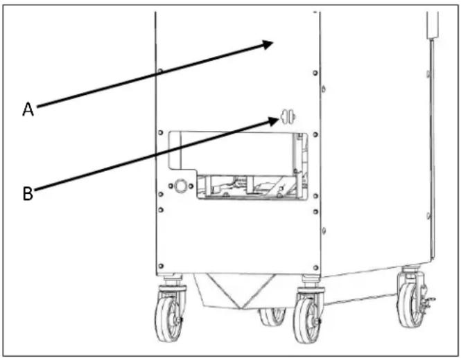
A Rear Of Fryer
B Strain Relief Chain Connection (Chain supplied by others)
The fryer must be installed with a connector (not supplied by Vulcan) complying with the above codes.
The fryer must be installed with restraining means to guard against transmission of strain to the connector. See illustration.
- The fryer must be installed with the casters provided.
- If the restraint is ever to be disconnected, first turn the gas supply off. If disconnection of the restraint is necessary, reconnect this restraint after the fryer has been returned to its originally installed position.
LEVELING THE FRYER
Check the level of the fryer by placing a level on top of the fryer after gas connections have been made.
Ensure that the fryer is level front-to-back and side-to-side in the final installed position.
If using casters, lock the wheels after unit is level.
OPERATION
⚠️ WAROTIIC and parts can cause burns. Use care when operating, cleaning and servicing the fryer.
⚠️ WSpRINHg Not frying compound can cause severe burns. Do not move fryer without draining all frying compound from the tank.
WARNING to be used during a power outage.
| FRYER CAPACITIES(PER FRY TANK) | |||||
| MODEL | # OF BURNERS | BTU/HR NATURAL GAS | BTU/HR PROPANE GAS | WIDTH INCH(CM) | SHORTENING LBS(KG) |
| VHG50 | 4 | 80,000 | 75,000 | 13-1/2(34.3) | 45-50(20.4 - 22.7) |
| VHG75 | 6 | 110,000 | 100,000 | 18(45.7) | 70(31.8) |
OVER-TEMPERATURE SHUTDOWN
If the shortening becomes overheated, a high-temperature shutoff device will turn the gas valve off. The shutoff device will automatically reset after the shortening cools down.
If the fryer shuts down due to overheating, DO NOT power up the fryer until the shortening temperature is below 300^ F ( 149^ C).
If an overheating situation persists, contact your local Vulcan authorized service office.
BEFORE FIRST USE
Cleaning
New units are wiped down at the factory to remove any visible signs of dirt, oil, grease, etc. remaining from the manufacturing process.
Before any food preparation, thoroughly wash the protective oil from all surface parts and the tank interior with hot soapy water to remove any film residue and dust or debris.
NOTICE not use chlorine or sulfate/sulfide cleaners.
- Wash any accessories shipped with unit.
- Rinse fryer and accessories thoroughly and drain the fryer.
- Wipe tank completely dry with a soft, clean cloth.
- Close the drain valve.
◆ Fill the fryer tank with liquid shortening.
VHG SERIES GAS FRYERS
FILLING THE FRY TANK WITH SHORTENING
NOTICE The fry tank must be filled with frying oil or water before turning the burners on. The fry tank can be damaged if the burners are turned on while empty and will void your warranty.
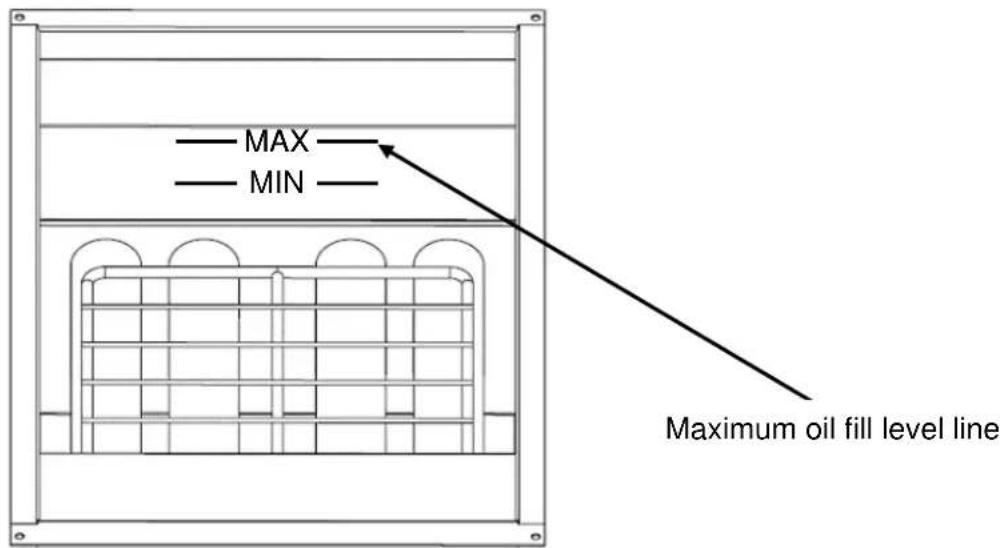
- Close the drain valve.
• Fill the fryer tank with frying oil or shortening.
• Oil level should be between the MIN and MAX lines on the fryer tank. - Oil will expand when heated. Do not fill the fryer tank past the MAX line.
- Add fresh shortening or frying oil as needed to maintain oil level.
NOTICE When using a solid shortening, ensure the shortening is packed tightly in the tank to eliminate any air pockets. Air pockets can cause ignition points and fry tank damage.
BASIC FRYING INSTRUCTION
Set the desired temperature and allow shortening to heat up to that temperature.
- Fry items that are the same size to ensure equal doneness.
- Drain or wipe dry raw or wet foods to minimize splatter when lowering into hot shortening.
- Add fresh shortening as needed.
VHG SERIES GAS FRYERS
Fry Basket Guidelines
- Do not overfill baskets. (See table for recommended basket capacities below). Carefully lower basket into oil.
- When frying doughnuts and fritters, turn product only once during frying.
- When cooking French fries or onion rings, shake the basket several times.
- Batter covered foods should be dropped carefully, one by one, into shortening or basket. If you use the basket, first dip the basket into the shortening to reduce batter-build up on basket surfaces.
- When frying is completed, remove basket or product. Hang basket on rear hanger.
Fry Basket Capacity:
VHG50: Recommended pounds per basket are 2.5 lbs. (1.1 kg).
VHG75: Recommended pounds per basket are 3.5 lbs. (1.6 kg).
EXTENDING SHORTENING LIFE
Shortening life can be extended by the following guidelines:
- Do not salt foods over the fryer.
- Use good-quality shortening.
◆ Filter shortening daily (at a minimum). - Replace shortening if it becomes poorly flavored.
- Keep equipment and surrounding clean. Use tank covers when not in use. (accessory).
- Set thermostat correctly.
- Remove excess moisture and particles from food products before placing in fryer.
TURNING ON THE FRYER
⚠ WARNING To prevent possible ignition of the shortening on start up, the melt mode must be set to solid mode when using a solid shortening.
NOTICE The fry tank must be filled with frying oil or water before turning the burners on. The fry tank can be damaged if the burners are turned on while empty and will void your warranty. Do not by-pass the dry fire test until proper oil or water level is confirmed.
Wait 5 minutes with power switch in the off position before starting to allow any gas that may have accumulated in the burner compartment to escape.
VHG SERIES GAS FRYERS
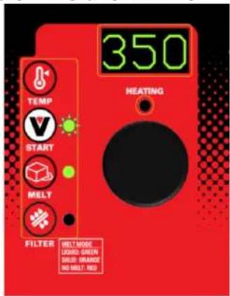
- Open the bottom fryer door and press the power switch to the ON position.
The controller will power on, show the current temperature setpoint in the display window and begin the dry fire test.
The START light flashes during dry fire test.
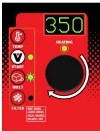
- The dry fire test can be by-passed by visually confirming oil level then pressing the START button.
Set the desired cooking temperature by turning the knob in either direction. The display will flash while making changes.
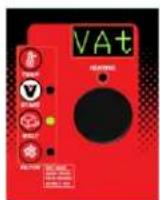
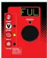
- If dry fire test fails, Vat FULL? PrESS START scrolls across the display window.
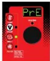
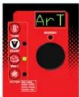
Confim that the fry tank is filled with oil. Press the START button to begin heating and melt cycle.
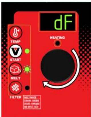
- Press and hold the TEMP button for 3 seconds to change the dry fire setting.
dF will display in the window. Turn the knob left and right to turn the dry fire option on or off.
Press the START button to save the selection.
NOTICE The dry fire Test function is an important feature intended to prevent the fryer burners from turning on with no liquid in the fry tank. It is recommended to be left in the on position. The fry tank can be damaged if the burners are turned on while empty and will void your warranty.
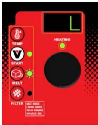
- Press the MELT button to cycle through to the correct setting to match the shortening type used.
GREEN- Liquid Melt Mode-Window displays L when MELT button is pressed. ORANGE-Solid Melt Mode-Window displays S when MELT button is pressed. RED- No Melt Mode-Window displays no when MELT button is pressed.
The MELT light flashes and the fryer will heat off and on until the vat temperature exceeds 135^ .
VHG SERIES GAS FRYERS
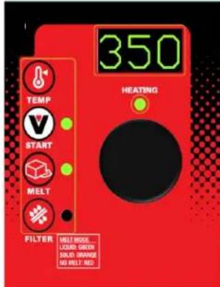
- Once temperature exceeds 135^ F (or if set To NO MELT), the fryer will heat continuously until the controller set point is reached.
The MELT light stays on continuously.
The HEATING light will go off once the setpoint is reached.
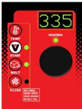
- The display window will always show the current temperature Setpoint.
Press the TEMP button to show the actual temperature for 3 seconds.
- Open the bottom fryer door and press the power switch to the off position.
⚠ WARNING Spilling hot frying compound can cause severe burns. Do not move fryer without draining all frying compound from the tank.
DRAINING THE TANK
Freestanding Models Without A Filter System Only:
- Turn off fryer.
- Insert the drain extension into the drain valve. Tighten only hand tight.
- Direct the drain spout into the container that you want to drain the shortening into.
- Open the drain valve. The oil will drain into the container. When the container is full or the fryer tank is empty, close the drain valve. Repeat this step until the fryer is empty. Remove the drain extension and place it back into the provided holder.
- It is recommended to now boil out your fry tank. Follow the Boil Out procedure. Then perform the weekly clean-out as described under CLEANING.
- Once tank is completely empty, boiled out and cleaned, close the drain valve and add new shortening. Follow the FILLING TANK WITH SHORTENING procedure in this manual.
- Turn on the power switch and follow the Turning On procedure for the control type to begin heating the oil to desired temperature.
BOIL OUT PROCEDURE
Weekly or when oil is replaced:
Freestanding Models Without A Filter System Only:
- Drain the tank as described under DRAINING THE OIL.
- Close the drain valve and fill tank with water. Use a boil out solid degreaser which can be ordered from your local dealer. Follow the instructions on the side of the package.
NOTICE Do not use chlorine or sulfate/sulfide cleaners.
-
Solution level must be between the MIN and MAX lines on the back of the fryer tank.
-
Turn the power switch to the on position, follow the Turning On procedure for the control type. With solid state knob controls (A), set the temperature setpoint 195^ F. Water boils at 212^ F. Do not bring water to a boil. Fryer boil over can result.
-
Use the tank brush; clean the sides, bottom and heat exchanger tubes.
-
Screw the drain extension in the drain valve and hand tighten only. Drain the cleaning solution from the tank into a container.
-
Close the drain valve and refill the tank with water. Add 1 cup (1/4 L) of vinegar to neutralize alkaline left by the cleaner. Solution level must be between the MIN and MAX line on the back of the fryer tank. Press the START button for (A) models to allow the solution to heat up. Allow solution to stand for a few minutes.
-
Drain the tank according to DRAINING THE TANK procedure. Rinse thoroughly with clear, hot water. All traces of cleaner must be removed. Dry the tank thoroughly.
-
Close the drain valve and add shortening. Follow the FILLING TANK WITH SHORTENING procedure in this manual.
-
The fryer is now ready for use. Turn on the power switch and follow the Turning On procedure for the control type to begin heating the oil to desired temperature.
CLEANING
⚠ WARNING Hot oil and hot parts can cause burns. Use care when operating, cleaning, and servicing the fryer.
Daily
Clean your fryer regularly with the tank brush along with a damp cloth, and polish with a soft dry cloth. If regular cleaning is neglected, grease will be burned on and discolorations may form.
Fingerprints are sometimes a problem on highly polished surfaces of stainless steel. They can be minimized by applying a cleaner that will leave a thin oily or waxy film.
- Clean all exterior surfaces of your fryer at least once daily.
VULCAN
F-47679 Rev. A (3-20)
VHG SERIES GAS FRYERS
- Use a damp cloth with warm water and a mild soap or detergent.
NOTICE not use chlorine or sulfate/sulfide cleaners.
◆ Rinse thoroughly, and then dry with a soft dry cloth.
- Keep the fryer exterior clean and free of accumulated grease to prevent stubborn stains from forming. If regular cleaning is neglected, grease will be burned on and discolorations may form.
- Remove discolorations by washing with any detergent or soap and water.
Use a self-soaping, non-metallic scouring pad for particularly stubborn discolorations.
- Always rub with the grain of the stainless steel.
- Do not use a metallic scoring pad or harsh cleaners.
EXTENDED SHUTDOWN
- Thoroughly drain the fryer. Refer to DRAINING THE FRYER.
- Clean the fryer according to CLEANING.
- Push Power switch to the off position
- Turn off the main gas shutoff valve.
The KleenScreen PLUS® filtration system filters the oil as it is pumped back into its' respective tank(s). Only one tank can be drained and filtered at a time. Under no circumstances should more than one tank be drained at the same time.
Assembly
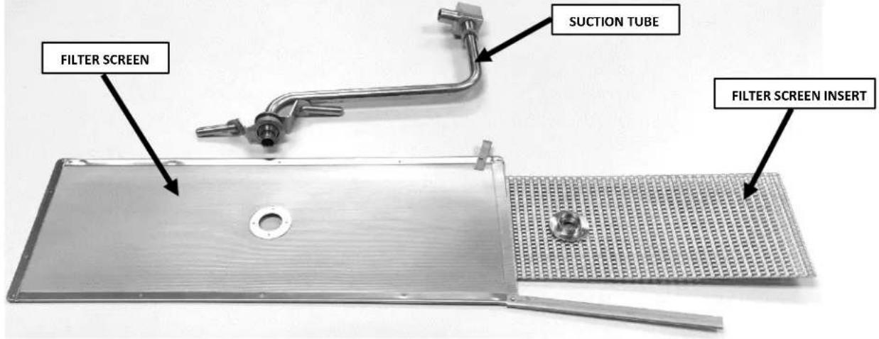
- After unpacking, wash the filter pan, crumb basket, suction tube and filter screen assembly. Make sure you remove the insert located inside the filter screen. Use dishwashing detergent and warm water, (parts are dishwasher safe). Rinse the filter pan, crumb basket and filter screen components completely and wipe all parts dry with a clean cloth.
• Pull out the filter pan all the way and remove to wash. - The filter pan slides can be removed for washing by pushing the slides back into the fryer. Then rotate the bottom of the slide toward the center of the fryer and lift out. Reverse the procedure to install.
VULCAN
F-47679 Rev. A (3-20)
VHG SERIES GAS FRYERS
- Slide the filter pan back into the drawer slides. Position the filter screen assembly into the suction tube clip in the filter pan positioning the filter screen assembly flat on the bottom of the filter pan.
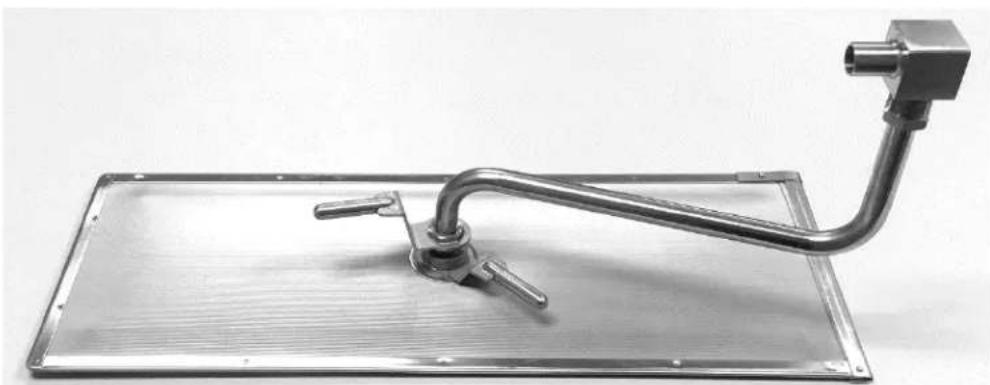
- Carefully line up the suction tube so that it mates with the oil receptacle block mounted on the frame of the fryer battery. Close the filter pan drawer. See Figures 1 and 2.
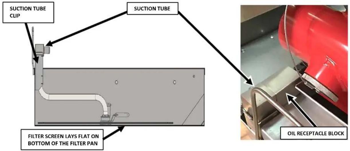
Fig.1
Fig.2
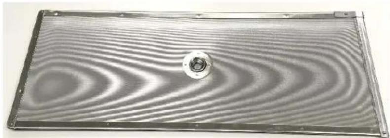
Fine Mesh Steel Filter Screen Assembly
natural_image
Metallic rectangular panel with concentric wavy patterns and a central circular feature (no text or symbols)- Slide the filter screen insert into the filter screen and align the center holes. Close the end latch to secure into place.
VHG SERIES GAS FRYERS
natural_image
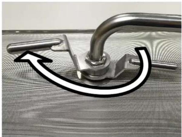
Close-up of a metallic pipe fitting with a curved arrow indicating rotation or movement (no text or symbols)- Insert suction tube into the filter screen hole. Align the threads of the top handle with the filter screen threads. Gently turn clockwise until tightened.
NOTICE Do not use tools. Hand tighten only.
natural_image
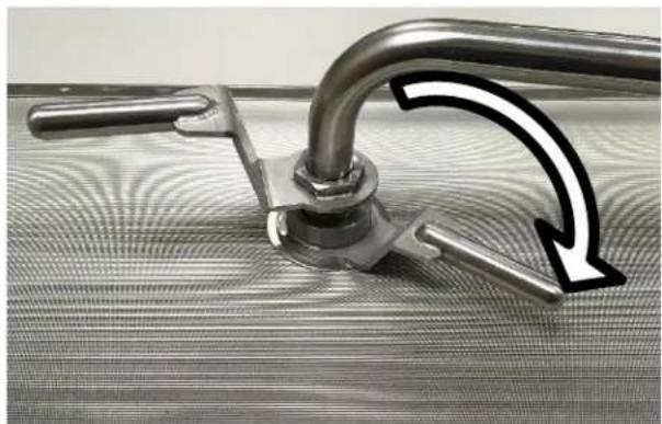
Close-up of a metallic pipe fitting with a curved arrow indicating rotation or compression (no text or symbols)- Gently turn the bottom handle clockwise until tightened.
NOTICE Do not use tools. Hand tighten only.
natural_image
Metallic mechanical device with a handle and mounting bracket mounted on a rectangular base (no text or symbols visible)Fig.3
Remove the fine mesh steel assembly from the filter pan and clean daily(or more frequently as required by your operation). Dissassemble the filter screen assembly by reversing steps 1-3 and removing the insert located inside the filter screen. Do not take the suction tube apart. Use dishwashing detergent and warm water, (parts are dishwasher safe).
VULCAN
F-47679 Rev. A (3-20)
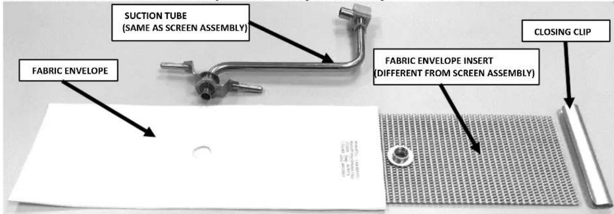
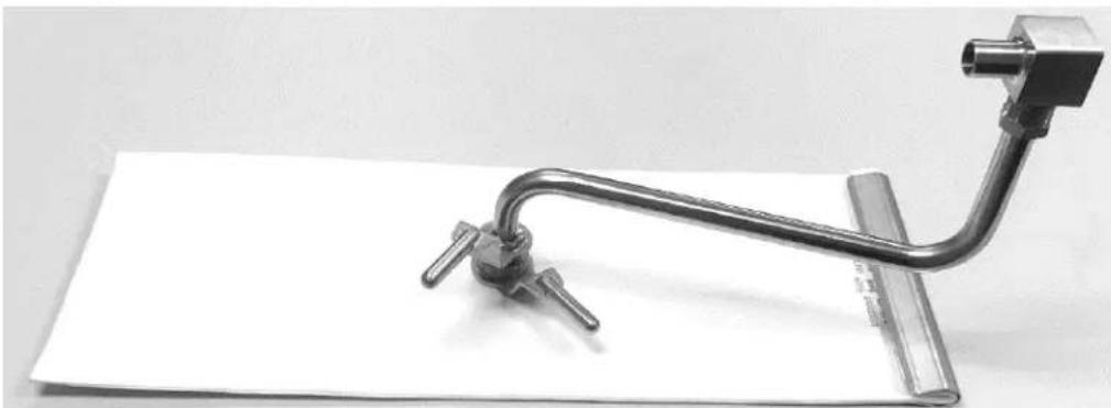
Micro-Filtration Fabric Envelope Accessory Assembly
natural_image
Mechanical clamp or clamp assembly with metal rod and attached bracket, mounted on a flat surface (no text or symbols visible)Fig.4
Slide the fabric envelope insert into the envelope and align the center holes. Fold over the open end of the envelope and place closing clip on – hinge over and firmly press clip all the way down to secure and seal filter assembly. Make sure that the folded end of the envelope is face down.
Attach suction tube in same manner as the screen assembly shown on previous page. Dissassemble the fabric envelope assembly by reversing steps.
NOTICE Do not use tools. Hand tighten only.
Remove the fabric envelope assembly from the filter pan and clean daily(or more frequently as required by your operation). Scrape debris and sludge from envelope surfaces with a spatula.
NOTICE Do not wash the fabric envelope.
VHG SERIES GAS FRYERS INSTRUCTIONS TO REMOVE & REPLACE KLEENSCREEN PLUS® FILTER ENVELOPE
FOR ABSOLUTE FILTRATION & MAXIMUM FLOW RATE WE RECOMMEND YOU CHANGE YOUR FILTER ENVELOPES AT EVERY OIL CHANGE (10-14 DAYS DEPENDING ON OIL USAGE).

WARNING Hot oil and parts can cause burns. Use care when operating, cleaning and servicing the fryer.
Step 1 Discard all oil from the filter vessel. When the filter pan is empty, use a spatula and scrape off all debris left on the filter envelope and in the filter pan.
Step 2 Unscrew the suction tube from filter by first turning the bottom handle fitting counter clockwise until completely loosened. Next, turn the top handle fitting counter clockwise until completely loosened.
Step 3 Remove the closing clip.
Step 4 Remove the envelope insert, wash insert with hot water and dry thoroughly. The envelope insert is dishwasher safe. Place the insert into a new KleenScreen PLUS® Filter envelope.
NOTICE Do not wash the fabric envelope.
Step 5 Slide the envelope insert Insert into the fabric envelope making sure that the holes line up. Fold over the open end of the envelope and place closing clip on – hinge over and firmly press clip all the way down to secure and seal filter assembly. Make sure that the folded end is face down. Attach the suction tube assembly by first tightening the top handle fitting and then tighten the bottom handle fitting.
NOTICE Do not use tools. Hand tighten only.
Step 6 Position the filter screen assembly into the suction tube clip in the filter pan, positioning the filter screen assembly flat on the bottom of the filter pan. Align the tube so that the end of the tube tube engages the oil receptacle fitting each time the drawer is opened and closed.
VHG SERIES GAS FRYERS
FILTERING PROCEDURE – KleenScreen PLUS® Models ONLY
⚠️ WARNING parts can cause burns. Use care when operating, cleaning and servicing the fryer.
⚠️ WSpRINING Not frying compound can cause severe burns. Do not move fryer without draining all frying compound from the tank.
NOTICE Never run water or boil out solution through filter and motor / pump. Doing so will void your fryer warranty.
NOTICE Filter ONLY one fry tank at a time to avoid overflow and spillage.
NOTICE Do NOT turn off the power to the fryer. Leave power on.
Filtering Solid State Knob Control
WARNING Hot oil and parts can cause burns. Use care when operating, cleaning and servicing the fryer. Do not leave unattended.
WARNING Spilling hot frying compound can cause severe burns. Do not move fryer without draining all frying compound from the tank.
NOTICE Never run water or boil out solution through filter and motor / pump. Doing so will void your fryer warranty.
NOTICE Do NOT turn off the power to the fryer. Leave power on.
NOTICE Filter ONLY one fry tank at a time to avoid overflow and spillage.
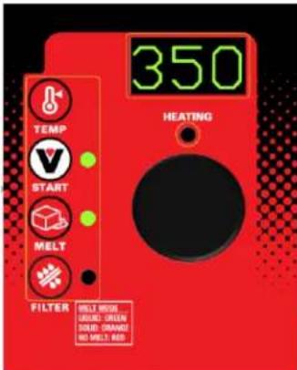
- Do NOT turn off the power to the fryer. Leave power on. Vulcan recommends adding an oil treatment media to the oil prior to filtering. Always filter the oil when hot at 300°F - 350°F.
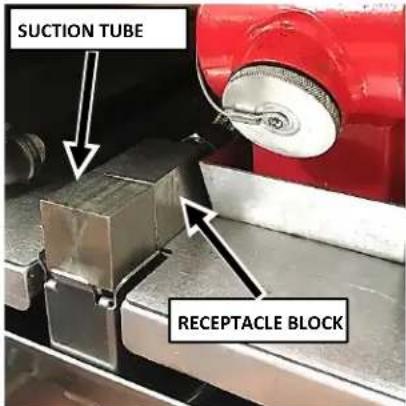
- Make sure that the filter drawer is closed completely and that the suction tube and receptacle block are in the correct position.
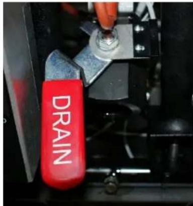
- Slowly open the drain valve to allow oil to flow from The fry tank to the filter pan. Then open the drain valve all the way. The fryer will automatically stop heating.
VHG SERIES GAS FRYERS
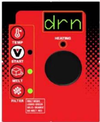
- The display will indicate drn. When the fry tank is empty, turn on the filter pump by pressing the filter icon button for 3-4 seconds. Allow the pump to filter the oil for a couple of minutes before closing the drain valve.
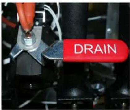
- Close the drain valve. The display will begin to scroll; FILL VAT-PRESS FILTER. The display will alternate from FILLING to PRESS FILTER. Fill to between the MIN and MAX lines on the back of the fryer tank. Oil will expand as it is heated. Do not fill the fryer tank past the MAX line.
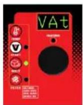
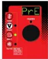
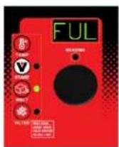
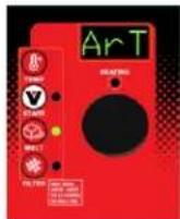
- Press the filter icon button again to stop the filter pump. The display will begin to scroll; VAT FULL?-PRESS START. Press the START(V) button. The fryer will then begin heating the oil to the desired temperature.
FLUSH/RINSE AND DISCARD OIL
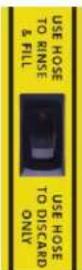
- Follow filtering instructions 1-3, however do not put oil treatment media into the fryer. Drain the fryer oil into the filter pan.
- Attach the quick disconnect hose to the discard male quick disconnect fitting.
- To discard the oil, place the nozzle end of the discard hose into a container that is large enough to retain the discarded shortening. Press the filter switch behind the door to the "USE HOSE TO DISCARD ONLY" position. This will allow all of the oil to be pumped through the hose only.
- For flushing/rinsing the tank with filtered oil to remove the particulates that have accumulated, press the filter switch behind the door to the "USE HOSE TO RINSE AND FILL" position. This will allow the oil to pass through the hose and come in from behind the tank at the same time.
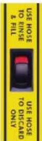
WARNING Oil will immediately exit out of the nozzle end of the hose any time the hose in plugged in and the filter pump is engaged.
- With the power switch still ON; press and hold the filter button for at least 3-4 seconds and the Motor/Pump will begin to operate.
- Once the oil has been discarded completely and the filter pan is empty, press the filter button to turn off the Motor/ Pump.
WARNING The hose connection will be hot due to the temperature of the oil that was discarded and can cause burns.
- Disconnect the discard hose. Be careful to let the hose drain before putting away. Close the drain valve and fill the fry tank with new oil.
NOTICE If discard vessel is not large enough to hold the entire shortening amount, stop the flow by pushing the filter button to to turn the motor/pump off. Empty the container and resume discard operation by pressing the filter holding for 3-4 seconds.
NOTICE If power is mistakenly turned off during the filtering operation, the corrective action is as follows.
- Close the drain valve
- Turn the power switch on
- Immediately open drain valve
- Continue filtering operation
VULCAN
F-47679 Rev. A (3-20)
VHG SERIES GAS FRYERS
FILTERING TIP:
Open the filtering drawer approximately 1" to allow any oil in the return line to run back into the filter pan. This will take about 30 seconds to complete. Then open the drawer completely to clean filter components.
REMOVING EXCESS DEBRIS FROM THE SCREEN FILTER:
WARNING
Hot oil and hot parts can cause burns.
NOTICE
Never run water or boil out solution through filter and motor / pump. Doing so will void your fryer warranty.
NOTICE
Filter ONLY one fry tank at a time to avoid overflow and spillage.
FILTERING TIP:
Open the filtering drawer approximately 1" to allow any oil in the return line to run back into the filter pan. This will take about 30 seconds to complete. Then open the drawer completely to clean filter components.
- Pull the filter drawer out.
- Remove the filter screen assembly. Scrape debris from the filter screen. Then remove the insert by unlatching the latch. Clean all parts thoroughly as mentioned in the assembly section on page 16.
- Scrape debris from the bottom of the filter pan and discard in the trash. Clean all parts thoroughly as mentioned in the Assembly section on page 16.
- Reassemble all filter components after being dried thoroughly as in the assembly section on page 16.
BOIL OUT PROCEDURE:
WARNING
Hot oil and hot parts can cause burns.
NOTICE
Never run water or boil out solution through filter and motor / pump. Doing so will void warranty.
- Discard oil as described under FLUSH/RINSE AND DISCARD OIL section
- Close the drain valve and fill tank with water. Use a boil out solid degreaser which can be ordered from your local dealer. Follow the instructions on the side of the package.
NOTICE
Do not use chlorine or sulfate /sulfide cleaners.
-
Solution level must be between the MIN and MAX levels on the fryer tank.
-
Turn the power switch to the on position. With solid state knob controls (A), set the temperature setpoint to 195^ F. Press the start button. Water boils at 212^ F.
VULCAN
F-47679 Rev. A (3-20)
VHG SERIES GAS FRYERS
Do not bring water to a boil. Fryer boil over can result.
-
Use the tank brush; clean the sides, bottom and heat exchanger tubes.
-
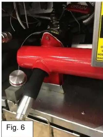
Unthread the Boil Out By-Pass™ drain plug and thread in the Boil Out By-Pass™ extension tube as shown in Fig. 6. The larger thread end screws into the back of the drain manifold as shown in the cutaway side view in Fig. 7.
-
Do not allow water to run through the motor/pump. Drain the boil out solution into a bucket or place a high temperature rated water hose on the end of the drain extension allowing the other end to flow into a floor drain.
-
Close the drain valve and refill the tank with water. Add 1 cup (1/4 L) of vinegar to neutralize alkaline left by the cleaner. Solution level must be between the MIN and MAX level on the fryer tank. Press the START(V) button on the solid state knob control (A), to allow the solution to heat up. Allow solution to stand for a few minutes.
-
Drain the tank by repeating step 7. Rinse thoroughly with clear, hot water. All traces of cleaner must be removed. Dry the tank thoroughly.
-
Close the drain valve and add shortening.
natural_image
Close-up of a red hydraulic cylinder mounted on a mechanical fixture, with visible wiring and components (no text or symbols)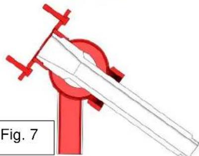
natural_image
Diagram of a mechanical clamp or clamp device with red clamps and a white rod, labeled 'Fig. 7' (no text or symbols on the diagram itself)THERMAL OVERLOAD PROTECTION BUTTON:
The motor/pump supplied with the filter system has a thermal overload protection circuit that senses when excess heat occurs. This can occur due to filtering for long periods of time or under heavy load prior to discarding debris buildup. If the thermal overload protection is tripped, wait 5 minutes and then reset the motor by pushing in the red button. The arrow in Figure 8 shows the location of the reset button; located on the right side of the motor / pump.
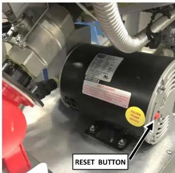
Fig 8.
⚠ WARNING The pump may start immediately when the reset button is pushed and begin circulating hot oil.
MAINTENANCE
⚠ WARNING and hot parts can cause burns. Use care when operating, cleaning, and servicing the fryer.
⚠️ WARNING hot fryer compound can cause severe burns. Do not move fryer without draining all frying compound from the tank.
⚠ WARNINGect the power supply to the fryer before servicing.
LUBRICATION
There are no parts that require lubrication.
FLUE VENT INSPECTION
When the fryer is cool, inspect annually. Check the flue and clear any obstructions.
ANNUAL INSPECTION
Contact an authorized service contractor for an annual inspection of the fryer.
SERVICE IN THE US AND CANADA
Contact the factory, the factory representative or authorized service contractor in your area to perform maintenance and repairs. For a complete listing of Service and Parts depots refer to www.vulcanequipment.com
ERROR MESSAGES
PILOT OUT – If the pilot is out, the digital control displays the following message:
"A" Solid State Knob – PLt
NO OR LOW GAS SUPPLY – If no action is taken after 90 seconds, the heat demand is disabled. The digital control displays the following message:
"A" Solid State Knob – PLt
The fryer must be turned off, then back on to re-initialize the control and to have normal functions resumed.
OPEN PROBE – If an open probe is detected, the heat demand is disabled. All operator buttons are disabled. The digital control displays the following message:
"A" Solid State Knob - oP
SHORTED PROBE – If a shorted probe is detected, the heat demand is disabled. All operator buttons are disabled. The digital control displays the following message:
"A" Solid State Knob – SP
Hi TEMPERATURE – If the temperature is greater than or equal to 415^ F ( 212^ C) or 40^ F above the setpoint, the heat demand is disabled. All operator buttons are disabled. The control displays the following message:
"A" Solid State Knob – HI
| TROUBLESHOOTING CHART | |
| PROBLEM | PROBABLE CAUSE |
| No heat | 1. Power switch not turned on2. Gas supply not turned on – check external gas valve on and gas hose properly connected3. Wire connections loose or need cleaning(Call service)4. High limit tripped(Call service)5. Check that power cord is plugged in properly |
| Insufficient or too much heat | 1. Temperature not adjusted to desired setpoint2. High limit tripped(Call service)3. Temperature probe(Call service)4. Gas pressure inadequate(Call service) |
| Tank will not drain | 1. Shortening is too cold. Heat oil to a minimum of 300° F.2. Drain pipe clogged with debris |
| Motor/pump will not pump oil | 1. Suction tube is not seated correctly in receptacle block.2. Filter screen or envelope is clogged and needs cleaning.3. Shortening is too cold. Heat oil to a minimum of 300° F.4. Discard switch is not properly set either for filtering or discarding.5. Motor thermal overload protection button is tripped. |
GUIDE D'INSTALLATION ET D'UTILISATION

FRITEUSES À GAZ SÉRIE VHG-A
AVEC SYSTÈME DE FILTRATION KLEENSCREEN PLUS ^MD
MODÈLES:
1VHG50A
1VHG75A
2VHG50A
2VHG75A
3VHG50A
3VHG75A
4VHG50A
4VHG75A

Modèle 1VHG75AF
SERVICE TECHNIQUE ET ASSISTANCE EN PIÈCES - US: 1-800-814-2028 | CANADA: 1-800-444-4764
Disconnect Devices for Use with Gas Fuel, ANSI z21.41.CSA 6.9 ou Quick-Disconnect Devices for Use with Gas Fuel.
natural_image
Metallic rectangular panel with concentric wavy patterns and a central circular feature (no text or symbols)natural_image
Close-up of a metallic pipe fitting with a curved arrow indicating rotation or movement (no text or symbols)natural_image
Close-up of a metallic tool handle with a curved handle and arrow indicating direction (no text or symbols)natural_image
Metallic mechanical device with a curved arm and three protruding pins, mounted on a rectangular base (no text or symbols visible)Fig. 3
natural_image
Mechanical clamp or bracket device attached to a flat sheet of paper, no visible text or symbolsFig. 4
natural_image
Four-panel image showing a metal clamp device, a close-up of a red spray bottle, and two blank white panels with handwritten labels (no readable text in panels)natural_image
Close-up of a red hydraulic cylinder mounted on a metal frame, with visible wiring and mechanical components (no text or symbols)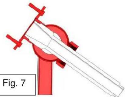
natural_image
3D diagram of a red mechanical clamp or clamp device with a white rod, labeled 'Fig. 7' (no text or symbols on the diagram itself)BOUTON DE LA PROTECTION CONTRE LES SURCHARGES THERMIQUES :

- IMPORTANT FOR YOUR SAFETY
- IMPORTANT
- FOR YOUR SAFETY
- WARNING
- TABLE OF CONTENTS
- INTRODUCTION
- GENERAL
- ORDERING PARTS
- UNPACKING
- VHG SERIES GAS FRYERS
- INSTALLATION
- Clearances
- Location
- CODES AND STANDARDS
- In the United States:
- In Canada:
- ASSEMBLY
- FLUE CONNECTION
- ELECTRICAL CONNECTION
- WARNING Electrical Grounding Instructions:
- GAS CONNECTION
- GAS PRESSURES (ALL MODELS):
- TESTING THE GAS SUPPLY PIPING SYSTEM:
- Fryers with Casters:
- LEVELING THE FRYER
- OPERATION
- OVER-TEMPERATURE SHUTDOWN
- BEFORE FIRST USE
- Cleaning
- FILLING THE FRY TANK WITH SHORTENING
- BASIC FRYING INSTRUCTION
- Fry Basket Guidelines
- Fry Basket Capacity:
- EXTENDING SHORTENING LIFE
- TURNING ON THE FRYER
- DRAINING THE TANK
- Freestanding Models Without A Filter System Only:
- BOIL OUT PROCEDURE
- Weekly or when oil is replaced:
- Daily
- NOTICE not use chlorine or sulfate/sulfide cleaners.
- EXTENDED SHUTDOWN
- VHG SERIES GAS FRYERS INSTRUCTIONS TO REMOVE & REPLACE KLEENSCREEN PLUS® FILTER ENVELOPE
- FILTERING PROCEDURE – KleenScreen PLUS® Models ONLY
- Filtering Solid State Knob Control
- FLUSH/RINSE AND DISCARD OIL
- REMOVING EXCESS DEBRIS FROM THE SCREEN FILTER:
- NOTICE
- FILTERING TIP:
- BOIL OUT PROCEDURE:
- THERMAL OVERLOAD PROTECTION BUTTON:
- MAINTENANCE
- LUBRICATION
- FLUE VENT INSPECTION
- ANNUAL INSPECTION
- SERVICE IN THE US AND CANADA
- ERROR MESSAGES
- GUIDE D'INSTALLATION ET D'UTILISATION
- FRITEUSES À GAZ SÉRIE VHG-A
- BOUTON DE LA PROTECTION CONTRE LES SURCHARGES THERMIQUES :
Brand : Vulcan
Model : 2VHG50AF
Category : Deep fryer