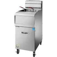
2TR45AF - Deep fryer Vulcan - Free user manual and instructions
Find the device manual for free 2TR45AF Vulcan in PDF.


| Brand | Vulcan |
| Model | 2TR45AF |
| Category | Gas fryer |
| Fuel type | Natural gas or propane |
| Vat capacity | Approximately 45 lb (20.4 kg) of oil |
| Basket capacity | 2.5 lb (1.1 kg) per basket (model 1VK/TR45) |
| Filtration system | KleenScreen PLUS® with pump |
| Temperature range | 135 °F to 400 °F (57 °C to 204 °C) |
| Control type | Solid-state (A or D) or computerized (C) |
| Melt function | For solid or liquid shortening |
| Safety shutdown | Overheat protection and ignition lockout |
| Filtration pump | With thermal protection and reset button |
| Gas connection | 1/2 in or 3/4 in inlet depending on configuration |
| Power supply | 120 V, 3-prong grounded plug |
| Vat material | Stainless steel |
| Included accessories | Baskets, crumb tray, brush, drain hose, casters |
| Maintenance | Daily cleaning, weekly draining and boil-out |
| Dimensions (approx.) | Width 40 cm, Depth 80 cm, Height 110 cm (with casters) |
| Weight (approx.) | 90 kg (with casters) |
| Standards | ANSI-Z223.1, NFPA 54, CSA B149.1 |
| Warranty | See manual for details |
Frequently Asked Questions - 2TR45AF Vulcan
User questions about 2TR45AF Vulcan
0 question about this device. Answer the ones you know or ask your own.
Ask a new question about this device
Download the instructions for your Deep fryer in PDF format for free! Find your manual 2TR45AF - Vulcan and take your electronic device back in hand. On this page are published all the documents necessary for the use of your device. 2TR45AF by Vulcan.
USER MANUAL 2TR45AF Vulcan
INSTALLATION & OPERATIONAL MANUAL
VK / TR / VFRY SERIES GAS FRYERS With KleenScreen PLUS® Filtration Systems
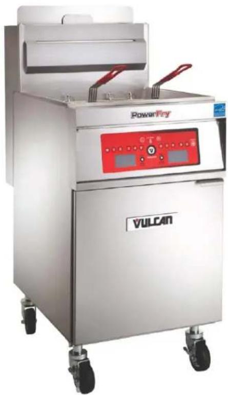
natural_image
Exterior view of a Power Fry air fryer with red control panel and wheels (no visible text or symbols on device body)1VK45C Shown
MODELS:
| 1VK45 | 1TR45 | ||
| 1VK65 | 1TR65 | ||
| 1VK85 | 1TR85 | ||
| 2VK45 | 2TR45 | ||
| 2VK65 | 2TR65 | ||
| 2VK85 | 2TR85 | ||
| 3VK45 | 3TR45 | ||
| 3VK65 | 3TR65 | ||
| 3VK85 | 3TR85 | ||
| 4VK45 | 4TR45 | ||
| 4VK65 | 4TR65 | ||
| 4VK85 | 4TR85 | ||
| 5VK45 | 5TR45 | ||
| 5VK65 | 5TR65 | ||
| 5VK85 | 5TR85 | ||
| 6VK45 | 6TR45 | ||
| 6VK65 | 6TR65 | ||
| 6VK85 | 6TR85 | ||
| 2MB | VFRY18 | ||
| 3MB | |||
| 4MB | |||
| 5MB | |||
| 6MB |
For additional information on Vulcan or to locate an authorized parts and service provider in your area, visit our website at www.vulcanequipment.com
IMPORTANT FOR YOUR SAFETY
THIS MANUAL HAS BEEN PREPARED FOR PERSONNEL QUALIFIED TO INSTALL GAS EQUIPMENT, WHO SHOULD PERFORM THE INITIAL FIELD START-UP AND ADJUSTMENTS OF THE EQUIPMENT COVERED BY THIS MANUAL.
POST IN A PROMINENT LOCATION THE INSTRUCTIONS TO BE FOLLOWED IN THE EVENT THE SMELL OF GAS IS DETECTED. THIS INFORMATION CAN BE OBTAINED FROM THE LOCAL GAS SUPPLIER.
IMPORTANT
IN THE EVENT A GAS ODOR IS DETECTED, SHUT DOWN UNITS AT THE MAIN SHUTOFF VALVE AND CONTACT THE LOCAL GAS COMPANY OR GAS SUPPLIER FOR SERVICE.
FOR YOUR SAFETY
DO NOT STORE OR USE GASOLINE OR OTHER FLAMMABLE VAPORS OR LIQUIDS IN THE VICINITY OF THIS OR ANY OTHER APPLIANCE.
WARNING
Improper installation, adjustment, alteration, service or maintenance can cause property damage, injury or death. Read the installation, operating and maintenance instructions thoroughly before installing or servicing this equipment.
TABLE OF CONTENTS
IMPORTANT FOR YOUR SAFETY.... 2
INTRODUCTION.... 4
GENERAL 4
ORDERING PARTS.... 4
UNPACKING.... 4
INSTALLATION.... 5
Clearances.... 5
Location 5
CODES AND STANDARDS.... 6
ASSEMBLY 6
FLUE CONNECTION.... 7
ELECTRICAL CONNECTION.... 7
GAS CONNECTION.... 8
Quick-Disconnect for Units on Casters.... 8
GAS PRESSURE....8
TEST GAS SUPPLY 8
FRYERS WITH CASTERS.... 8
LEVELING THE FRYER.... 9
OPERATION.... 10
OVER-TEMPERATURE SHUTDOWN.... 10
BEFORE FIRST USE.... 10
Cleaning....10
BASIC FRYING INSTRUCTIONS.... 11
Fry Basket Guidelines.... 11
Fry Basket Capacity.... 11
EXTENDED SHORTENING LIFE.... 11
TURNING ON THE FRYER 12
PROGRAMMING THE SOLID STATE KNOB (A) CONTROL.... 13
PROGRAMMING THE SOLID STATE (D) CONTROL.... 14
PROGRAMMING THE COMPUTER (C) CONTROL.... 15
TURNING OFF THE FRYER 15
DRAINING THE TANK – FREE STANDING FRYERS...... 16
BOIL OUT PROCEDURE – FREE STANDING FRYERS 16
CLEANING.... 17
Daily....17
EXTENDED SHUTDOWN.... 17
KLEENSCREEN PLUS® INSTALLATION & OPERATION MANUAL..... 18
GENERAL 18
ASSEMBLY.... 18
REMOVE & REPLACE KLEENSCREEN PLUS® FILTER ENVELOPE... 20
OPERATION.... 21
FILTERING PROCEDURE.... 21
FILTERING SOLID STATE KNOB (A) CONTROLS.... 23
FILTERING SOLID STATE (D) CONTROLS 24
FILTERING COMPUTER (C) CONTROLS 25
FILTERING TIP 26
REMOVING EXCESS DEBRIS FROM THE FILTER.... 26
FLUSH AND DISCARD.... 26
BOIL OUT BYPASS™ 27
THERMAL OVERLOAD PROTECTION RESET BUTTON...... 27
MAINTENANCE.... 28
FLUE VENT INSPECTION.... 28
Service in the US and Canada.... 28
Alarms and Error Messages.... 28
TROUBLESHOOTING.... 29
Troubleshooting Chart.... 29
INTRODUCTION
GENERAL
Vulcan Fryers are produced with quality workmanship and material. Proper installation, usage and maintenance will result in years of satisfactory performance.
Before installing the fryer, thoroughly read this manual and carefully follow all instruction.
This manual is applicable to models listed on the cover page. Procedures in this manual will apply to all models unless specified. Pictures and illustrations can be of any model unless the picture or illustration needs to be model specific.
ORDERING PARTS
Customers may order parts directly from their local authorized service center. If not known, call Vulcan Customer Service at 800-814-2028.
To speed up your order, provide the model number, serial number, gas type, part needed, item part number (if known) and quantity needed.
UNPACKING
This fryer was carefully inspected before leaving the factory. The carrier assumes full responsibility for the safe delivery upon acceptance of the shipment. Check for possible shipping damage immediately after receipt.
If the fryer is found to be damaged, complete the following steps:
- Carrier must be notified within 5 business days of receipt.
- Carrier's local terminal must be notified immediately upon discovery (note time, date, and who was spoken to), and follow up and confirm with written or electronic communication.
- All original packing materials must be kept for inspection purposes.
- The fryer cannot have been moved, installed, or modified.
- Notify Vulcan Customer Service immediately at 800-814-2028.
Check that the following have been included:
- Crumb Rack(s)
♦ Basket Hanger(s)
♦ Tank Brush for Boil Out Procedure Only - Adjustable Casters (4) two locking, two non-locking for freestanding fryers. Fryer Batteries with the KleenScreen PLUS® Filtration System have casters installed from the factory.
- Drain Pipe Extension for freestanding fryers only.
♦ Twin Fry Baskets (2) per fry tank - Cleanout Rod
- Fryer Batteries with the KleenScreen PLUS® Filtration System
- Filter Pan
VK / TR / VFRY SERIES GAS FRYERS
- Suction Tube
- Screen Assembly
• High temperature discard hose
- Manual, Quick Start Guide(s), and Warranty – Keep in safe place for future reference.
INSTALLATION
Do not use the door or its handle to lift the fryer.
Before installing the fryer, verify that the type of gas (natural or propane) agrees with the specifications on the fryer data plate, which is located on the inside of the door panel. Make sure the fryer is configured for the proper elevation.
Record your fryer model, device, and serial numbers for future reference in the space provided below. This information can be found on the fryer data plate.
Fryer Model No: ____
Device:
Serial No: ____
Clearances
◆ Minimum clearance from combustible construction:
6" (15 cm) from the sides of the fryer 6" (15 cm) from the back of the fryer The fryer may be installed on combustible floors
◆ Minimum clearance from noncombustible construction:
0" from the sides of the fryer 0" from the back of the fryer
- Between the fryer and any open-top flame units:
16" (41 cm)
- Allow space for servicing and operation.
Location
- Install fryer in an area with sufficient air supply for gas combustion.
- Do not obstruct the flow of combustion and ventilation air.
- Provide adequate clearance for air openings into the combustion chamber.
- Do not permit fans to blow directly onto fryer.
VK / TR / VFRY SERIES GAS FRYERS
- Keep the fryer area free and clear from combustibles.
- Avoid wall-type fans, which create cross-currents within a room. Avoid open windows next to sides or back.
CODES AND STANDARDS
The fryer must be installed in accordance with:
In the United States:
- State and local codes, or in the absence of local codes, with:
- National Fuel Gas Code, ANSI-Z223.1/NFPA #54 (latest edition). Copies may be obtained from The American Gas Association Accredited Standards Committee Z223, @ 400 N. Capital St. NW, Washington, DC 20001 or the Secretary Standards Council, NFPA, 1 Batterymarch Park Quincy, MA 02169-7471.
◆ NFPA Standard #96 Vapor Removal from Cooking Equipment, latest edition, available from the National Fire Protection Association, Batterymarch Park, Quincy, MA. 02169-7471. - National Electrical Code, ANSI/NFPA-70 (latest edition). Copies may be obtained from The National Fire Protection Association, Batterymarch Park, Quincy, MA. 02169-7471.
- In the commonwealth of Massachusetts all gas appliances vented through a ventilation hood or exhaust system with a damper or with a power means of exhaust shall comply with 248 CMR.
In Canada:
- Local codes
CAN/CSA-B149.1 Natural Gas and Propane Installation Code (latest edition), available from the Canadian Standards Association, 155 Queen Street, Suite 1300, Ottawa, Ontario Canada K1P 6L1. - CSA C22.1 Canadian Electric Code (latest edition), available from the Canadian Standards Association, 155 Queen Street, Suite 1300, Ottawa, Ontario Canada K1P 6L1.
ASSEMBLY
The fryer must be restrained to prevent tipping and the splashing of hot liquid. The means of restraint may be the manner of installation, such as connection to a battery of appliances, installing the fryer in an alcove, or by separate means such as adequate ties.
FLUE CONNECTION
Make the flue connection as follows:
Comply with Vapor Removal from Cooking Equipment, ANSI-NFPA Standard #96 (latest edition), available from the National Fire Protection Association, Batterymarch Park, Quincy, MA 02269.
- Locate the fryer under a hood with adequate connection to an exhaust duct. The hood must extend 6" (15 cm) beyond fryer on both sides.
- Clearance above the fryer should be adequate for combustion byproducts to be removed efficiently.
- An 18" (46 cm) minimum clearance should be maintained between the flue vent and the filters of the hood venting system.
- Never make flue connections directly to the fryer.
Do not obstruct the flow of the gases from the appliance. Proper air balance should be maintained in the room.
- Ensure that your ventilation system does not cause a down draft at the fryer's flue opening. Down drafts will not allow the fryer to exhaust properly and will cause overheating which may cause permanent damage. Damage caused by down drafts will not be covered under equipment warranty. NEVER allow anything to obstruct the flue of combustibles or ventilation exiting from the fryer flue. DO NOT put anything on top of flue area.
ELECTRICAL CONNECTION
WARNING Electrical Grounding Instructions:
This appliance is equipped with a three prong (grounding) plug for your protection against shock hazard and should be plugged directly into a properly grounded three-prong receptacle. Do not cut or remove the grounding prong from this plug. Fryer must be electrically grounded in accordance with local codes, or in the absence of local codes, with the National Electrical Code, ANSI/NFPA 70, or the Canadian Electrical Code, CSA C22.2, as applicable.
Electrical diagram located on inside of door.
GAS CONNECTION
NOTICE gas supply connections and any pipe joint compound must be resistant to the action of propane gases.
The gas inlet is located on the lower rear of the fryer. Codes require that a gas shutoff valve be installed in the gas line ahead of the fryer.
The gas supply line must be at least the equivalent of 12 " (12.7 mm) iron pipe for single units and 1-1/4" (31.75 mm) for batteries. If using the optional quick-disconnect flex hose, 34 " (19 mm) iron pipe for single units and 1-1/4" (31.75 cm) iron pipe for batteries.
Make sure the pipes are clean and free of obstructions, dirt, and piping compound. A battery requires one or two connections of appropriate size for the gas requirement.
APWARNING, check all joints in the gas supply line for leaks. Use soap and water solution. Do not use an open flame.
After piping has been checked for leaks, fully purge gas pipes to remove air.
GAS PRESSURES (ALL MODELS):
The gas measured exiting the gas valve should be set at .08" W.C. (Water Column) (0.02 kPa) for natural gas and .08" W.C. (0.02 kPa) for propane gas. This fryer has been gas calibrated at the factory to achieve maximum performance. Do not make any adjustments to the gas valve assembly. The supply pressure should be 7-9" W.C. for natural gas and 11-12" W.C. for propane gas. If incoming pressure exceeds 14" WC ( 12 psig -3.45 kPa), a step-down pressure regulator must be installed.
TESTING THE GAS SUPPLY PIPING SYSTEM:
When test pressures exceed 12 psig (3.45 kPa), the fryer and its individual shutoff valve must be disconnected from the gas supply piping system.
When test pressures are 12 psig (3.45 kPa) or less, the fryer must be isolated from the gas supply piping system by closing its individual shutoff valve.
Fryers with Casters:
Separate instructions for installing casters are included with the casters:
- The installation shall be made with a connector that complies with the Standard for Connectors for Movable Gas Appliances, ANSI Z21.69, CAN/CGA-6.16, and a quick-disconnect device that complies with the Standard for Quick-
Disconnect Devices for Use with Gas Fuel, ANSI z21.41.CSA 6.9 or Quick-Disconnect Devices for Use with Gas Fuel.
- When installing a quick disconnect you must also install a means for limiting the movement of the fryer. This device will prevent the gas line or quick disconnect from being strained. The restraining device should be attached to the cutout on the back panel. See illustration for location.
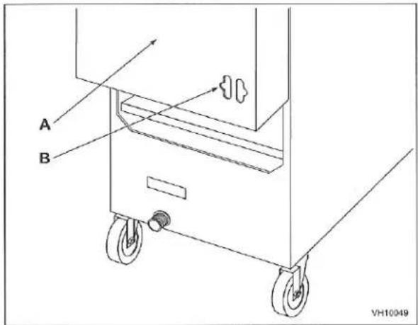
text_image
A B VH10049A Rear of Fryer
B Strain Relief Chain Connection (Chain supplied by others)
- The fryer must be installed with a connector (not supplied by Vulcan) complying with the above codes.
- The fryer must be installed with restraining means to guard against transmission of strain to the connector. See illustration.
- The fryer must be installed with the casters provided.
- If the restraint is ever to be disconnected, first turn the gas supply off. If disconnection of the restraint is necessary, reconnect this restraint after the fryer has been returned to its originally installed position.
LEVELING THE FRYER
Check the level of the fryer by placing a level on top of the fryer after gas connections have been made.
Ensure that the fryer is level front-to-back and side-to-side in the final installed position.
If using casters, lock the wheels after unit is level.
OPERATION
⚠ WARNING and parts can cause burns. Use care when operating, cleaning and servicing the fryer.
⚠️ Warming got frying compound can cause severe burns. Do not move fryer without draining all frying compound from the tank.
WARNING to be used during a power outage.
OVER-TEMPERATURE SHUTDOWN
If the shortening becomes overheated, a high-temperature shutoff device will turn the gas valve off.
If the fryer shuts down due to overheating, DO NOT power up the fryer until the shortening temperature is below 300^ F ( 149^ C).
If an overheating situation persists, contact your local Vulcan authorized service office.
BEFORE FIRST USE
Cleaning
New units are wiped down at the factory to remove any visible signs of dirt, oil, grease, etc. remaining from the manufacturing process.
Before any food preparation, thoroughly wash the protective oil from all surface parts and the tank interior with hot soapy water to remove any film residue and dust or debris.
NOTICE Not use chlorine or sulfate/sulfide cleaners.
♦ Wash any accessories shipped with unit.
- Rinse fryer and accessories thoroughly and drain the fryer.
- Wipe tank completely dry with a soft, clean cloth.
◆ Close the drain valve.
◆ Fill the fryer tank with liquid shortening.
- Shortening level should be between the min and max lines in the fryer tank.
◆ Shortening will expand when heated. Do not fill the fryer tank past the MAX line.
- Add fresh shortening as needed to maintain oil level.
BASIC FRYING INSTRUCTION
- Set the desired temperature and allow shortening to heat up to that temperature.
- Fry items that are the same size to ensure equal doneness.
- Drain or wipe dry raw or wet foods to minimize splatter when lowering into hot shortening.
- Add fresh shortening as needed.
Fry Basket Guidelines
- Do not overfill baskets. (See table for recommended basket capacities below) Carefully lower basket into oil.
- When frying doughnuts and fritters, turn product only once during frying.
- When cooking French fries or onion rings, shake the basket several times.
- Batter covered foods should be dropped carefully, one by one, into shortening or basket. If you use the basket, first dip the basket into the shortening to reduce batter-build up on basket surfaces.
- When frying is completed, remove basket or product. Hang basket on rear hanger.
Fry Basket Capacity:
1VK / TR45 & VFRY18: Recommended pounds per basket are 2.5 lbs. (1.1 kg).
1VK / TR65: Recommended pounds per basket are 3.0 lbs. (1.4 kg).
1VK / TR85: Recommended pounds per basket are 3.5 lbs. (1.6 kg).
EXTENDING SHORTENING LIFE
Shortening life can be extended by the following guidelines:
- Do not salt foods over the fryer.
- Use good-quality shortening.
◆ Filter shortening daily (at a minimum). - Replace shortening if it becomes poorly flavored.
- Keep equipment and surrounding clean. Use tank covers when not in use. (accessory).
- Set thermostat correctly.
- Remove excess moisture and particles from food products before placing on fryer.
TURNING ON THE FRYER
(VK / TR / VFRY) A solid state knob control:
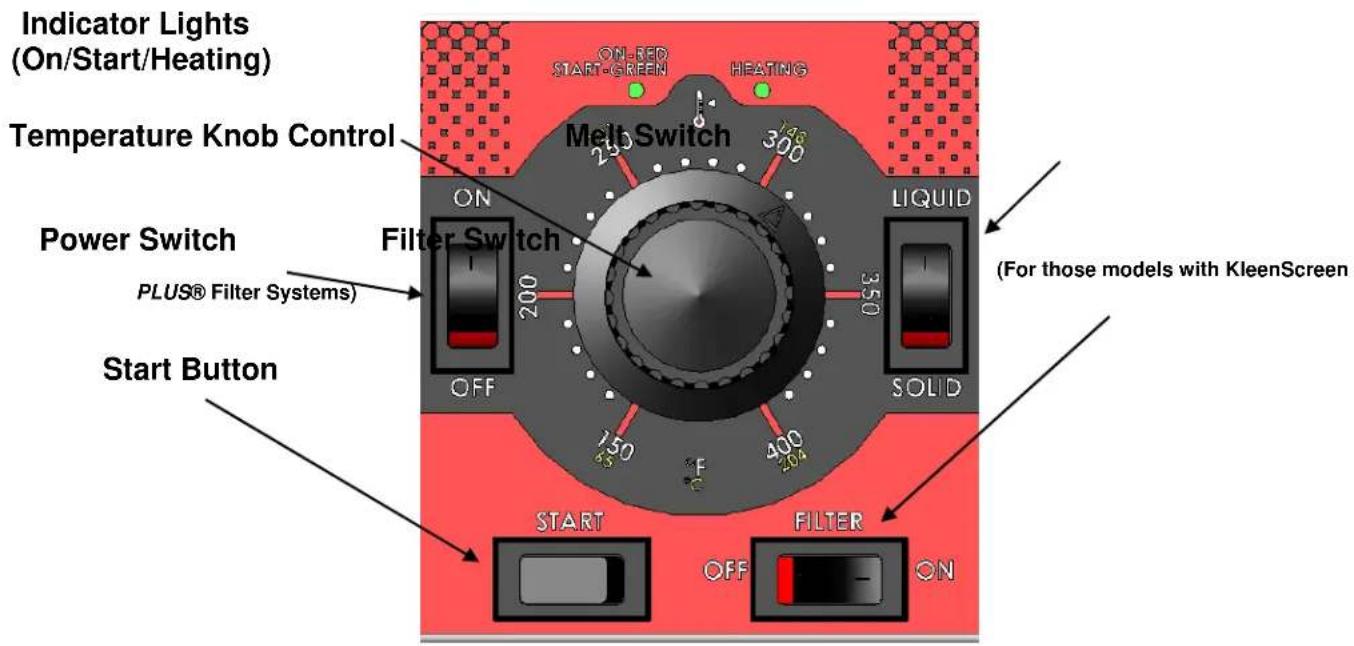
text_image
Indicator Lights (On/Start/Heating) ON-RED START-GREEN HEATING Melt Switch Temperature Knob Control ON 200 300 350 LIQUID Power Switch PLUS® Filter Systems Filter Switch OFF 350 400 200 SOLID For those models with KleenScreen Start Button START FILTER OFF ON- Open the door to the fryer. Select Liquid or Solid Shortening by pressing the switch to the desired selection.
- Set temperature by turning the knob to the desired temperature.
- Press the power switch to the ON position. The burners will not light until the next step is completed.
- Press the START switch once for the burners to light. The START switch is a momentary switch and will reset after being pressed. The indicator light will change from Red to Green. Heating light will glow Yellow.
- The power burner will cycle on and off throughout the melt cycle. When the fry tank oil reaches 135^ F the burners will stop cycling and remain on until the set temperature is reached. Once set temperature is reached the burners will cycle on and off to maintaining the set temperature.
(VK / TR)D solid state digital and (VK / TR)C programmable controls:
For solid state digital and programmable computer controls the power burner will light automatically. The power burner will cycle on and off throughout the melt cycle and continue afterwards maintaining the set temperature.
VULCAN FRYERS

SOLID STATE CONTROLS GUIDE

DONE TO PERFECTION.
START UP in 4 Easy Steps
STEPS 1-4
TURNING ON THE FRYER
natural_image
Red electronic device with black rotary knob and control buttons (no visible text or symbols)Fill fry tank with oil. Press the power switch ON. The red light will come on.
text_image
2 ON OFF LQUB ON OFF LQUBSet temperature knob to the desired set temperature.
text_image
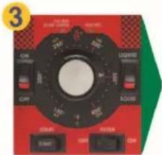
3 ON OFF SQUIN ON OFF ON OFF ONMove the MELT switch to the correct shortening being used: Solid or Liquid.
text_image
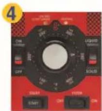
4 ON OFF VETER START ON QTY LUXIDE ON ON SALADPress the START switch and fryer will begin to heat. The burners or heating elements will cycle on and off through the melt cycle. When temperature reaches 135°F the burner or heating element will stay on until set temperature is reached. The red light will change to green. When the fryer calls for heat the yellow light with come on.
Open the door to the fryer. Press the power switch to the OFF position
SOLID STATE KNOB CONTROLS GUIDE
FILTER SWITCH (for those models with KleinScreen PLUS® Filter Systems)
WARNING
HOT FRYING COMPOUND AND PARTS CAN CAUSE BURNS. USE CARE WHEN OPERATING, CLEANING, OR SERVICING THE FRYER. USE CARE WHEN FILTERING. DO NOT LEAVE UNATTENDED.
SPILLING HOT FRYING COMPOUND CAN CAUSE SEVERE BURNS. DO NOT MOVE THE FRYER WITHOUT FIRST DRAINING ALL FRYING COMPOUND FROM TANK.
NOTICE IF POWER IS MISTAKENLY TURNED OFF DURING THE FILTERING OPERATION, THE CORRECTIVE ACTION IS AS FOLLOWS
- CLOSE DRAIN VALVE
- TURN POWER SWITCH ON
- IMMEDIATELY OPEN DRAIN VALVE
- CONTINUE FILTERING OPERATION PER STEPS 1-7 USING FILTERING GUIDE
VULCAN FRYERS

SOLID STATE CONTROLS GUIDE

DONE TO PERFECTION.
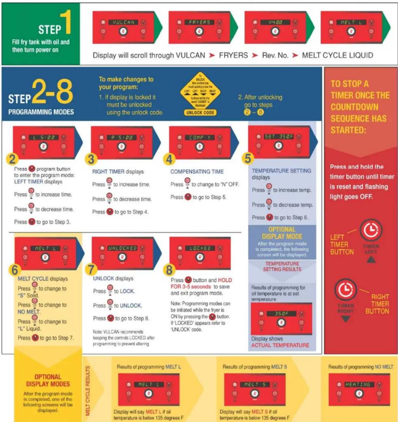
PROGRAMMING in 8 Easy Steps (for revisions V4.00 or higher)
text_image
STEP 1 Fill fry tank with oil and then turn power on Display will scroll through VULCAN ▶ FRYERS ▶ Rev. No. ▶ MELT CYCLE LIQUID STEP 2-8 PROGRAMMING MODES To make changes to your program: 1. If display is locked it must be unlocked using the unlock code. 2. After unlocking go to steps 2 - 3 2 Press program button to enter the program mode: LEFT TIMER displays Press to increase time. Press to decrease time. Press to go to Step 3. 3 RIGHT TIMER displays Press to increase time. Press to decrease time. Press to go to Step 4. 4 COMPENSATING TIME Press to change to "N" OFF. Press to go to Step 5. 5 TEMPERATURE SETTING displays Press to increase temp. Press to decrease temp. Press to go to Step 6. 6 MELT L MELT CYCLE displays Press to change to "S" Solid. Press to change to NO MELT. Press to change to "L" Liquid. Press to go to Step 7. 7 UNLOCKED UNLOCK displays Press to LOCK. Press to UNLOCK. Press to go to Step 8. Note: VULCAN recommends keeping the controls LOCKED after programming to prevent altering 8 UPPS button and HOLD FOR 3-5 seconds to save and exit program mode. Note: Programming modes can be initiated while the fryer is ON by pressing the 'L' button. If 'LOCKED' appears refer to 'UNLOCK' code. 9 TEMPERATURE SETTING RESULTS Results of programming for oil temperature is at set temperature 10 358F Display shows ACTUAL TEMPERATURE TO STOP A TIMER ONCE THE COUNTDOWN SEQUENCE HAS STARTED: Press and hold the timer button until timer is reset and flashing light goes OFF. LEFT TIMER BUTTON TIMER LEFT RIGHT TIMER BUTTON OPTIONAL DISPLAY MODE After the program mode is completed, the following screen will be displayed. TEMPERATURE SETTING RESULTS Results of programming for oil temperature is at set temperature 358F Display shows ACTUAL TEMPERATURE OPTIONAL DISPLAY MODES After the program mode is completed, one of the following screens will be displayed. Results of programming MELT L Display will say MELT L if oil temperature is below 135 degrees F Results of programming MELT S Display will say MELT S if oil temperature is below 135 degrees F Results of programming NO MELTVULCAN FRYERS

COMPUTER CONTROLS GUIDE
PROGRAMMING in 7 Easy Steps (for revisions V2.79 or higher)
START
Fill fry tank with oil and then turn power on.
Display will scroll through VULCAN FRYER ▶ Rev. No. ▶ MELT CYCLE LIQUID
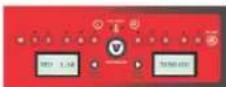
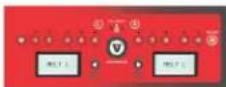
STEP 1-7
PROGRAMMING MODES
UNLOCK CODE
- If display is locked it must be unlocked using the unlock code.
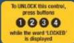
2. After unlocking go to steps ① - ⑦

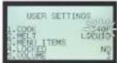
Press program button. Ⓧ USER SETTINGS displays. To set cook temperature, press ⏻ The current temperature will begin to flash. Type in the revised temperature. Press Ⓧ to save your new cook temperature.

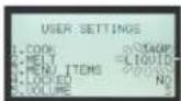
To set the melt cycle, press 2. The LIQUID display will begin to flash. Press the button to select, LIQUID, SGLID, and NO MELT options. Press to save your melt cycle.

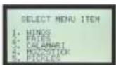
To set Cook Time manually, press SELECT MENU ITEM will display
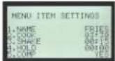
Select an item to be edited by pressing the corresponding number 1-10. The menu will change to allow edits to the menu item selected using the MENU ITEM SETTINGS in the right display.
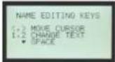
3a Press 1 to edit the NAME of the menu item and follow the directions on the right display. To change the letters press button 1 move towards the beginning of the alphabet and button 2 to move towards the end of the alphabet. The LED above the button selected for the menu item to be edited will be it and the evaluable parameters for editing will be listed in the right display. Press 1 to save the new NAME of the menu item.
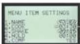
3b Press ② to change the COOK TIME. The current time will flash. Type in the new COOK TIME. Press ⑦ to save your new COOK TIME.
3c Press 3 to edit the SHAKE TIME. The current shake time will flash. Type in the new SHAKE TIME. Press 9 to save your new SHAKE TIME.
3d Press 4 to change the HOLD TIME. The HOLD TIME will flash. Type in the new HOLD TIME. Press 7 to save your new HOLD TIME.
3e Press 5 to choose COMPENSATING TIME or ACTUAL TIME. YES will begin to flash. Press the button to select YES for COMP TIME or NO for ACTUAL TIME. Press 6 to save your selection. Press 7 again to exit MENU ITEM SELECTION and return to SELECT MENU ITEMS.

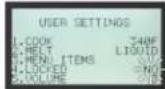
Press the program button √ USER SETTINGS displays. To Lock control or keep the computer UNLOCKED press 🔒 The current setting will flash. Press the 🔒 button to select YES or NO Press 🔒 to save your selection.

To adjust the Beeper VOLUME, press 5. The current setting will flash and will sound. Press the button to select 1, 2 or 3. Press to save your selection.

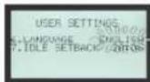
To set Language, press 6. The current setting will flash. Press the button to select ENGLISH, SPANISH, or FRENCH. Press to save your selection.

To set the IDLE SETBACK, press 7. The current time will flash. Type in the new IDLE TIME (10-99 minutes). Press 📋 to save your new IDLE SETBACK time. Press 📋 again to SAVE ALL OF YOUR SETTINGS and exit the programming mode. MENU ITEMS will display.

DONE TO PERFECTION.
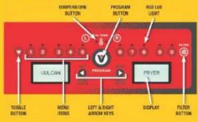
DISPLAY PANEL CONTROL GUIDE
text_image
TEMPERATURE BUTTON PROGRAM BUTTON HOLD LIME LIGHT 1 2 3 4 5 V ULCAN PROGRAM FRYER TODGLE BUTTON MENU IFENS LEFT & RIGHT ARROW KEYS DISPLAY FILTER BUTTONTO REVIEW SETTINGS:
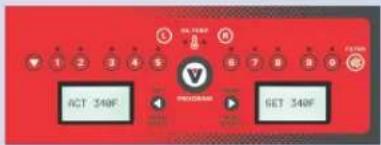
To REVIEW SETTINGS, press the OIL TEMP button. ACT temperature displays. Set temperature displays
text_image
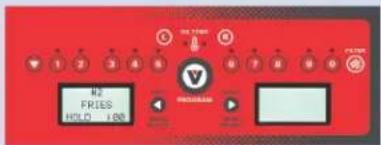
ACT 340F GET 340FHit ⬆ LEFT or RIGHT ▶ arrow, followed by desired product key 1 - 0 Display will scroll through settings for Time, Shake, Hold, and Cook Cycle.
text_image
H2 FRIES HOLD LINEOFFLINE PROGRAMMING WITH SOFTWARE MENU PROGRAM:
(Desktop or Laptop computer required. Download the
Menu Programming Software from www.vulcanequipment.com
To load a new product menu using the software menu program offline with a desktop or laptop computer:
1. With power switch in OFF position, insert USB memory drive.
2. Turn power switch ON and allow computer to complete start-up diagnostics before proceeding. Allow 2-3 minutes.
3. Press to start at USER SETTINGS screen.
4. From the USER SETTINGS screen, press
5. Quickly press the toggle button once.
6. Press the ① to select file.
7. Press key to confirm.
8. Remove USB memory device and confirm program was loaded.
OPERATION TIPS:
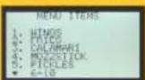
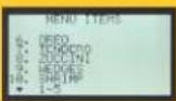
• To scroll through Menu items 1-10 press the button
• To activate a cook cycle timer press a button 1. First push the desired cook timer button and then press 1 or 2 corresponding to which basket is being used. Example: 2 L 5 R NOTE: You can use the same button for both 1 and 2 baskets. For example, 4 L 4 R.
• To cancel a cook timer, press and release the Ⓞ or Ⓔ button and the corresponding number button 1 - 0. The timer will stop and reset.
- With single basket lift fryers only press timer buttons 1 - 8 to activate the basket lift. There is no need to use the ① and ② buttons. To cancel the timer, press the same button again and the basket will raise up.
- Product keys blink when activated and are solid when programming.
• To silence alarm when timer is complete, press flashing menu item.
• VULCAN recommends keeping the controls LOCKED after programming to prevent altering.
- Press the power switch to the off position.
VULCAN
F-32971 Rev. S (01-17)
DRAINING THE TANK
Freestanding Models ONLY:
- Turn off fryer.
- Insert the drain extension into the drain valve. Tighten only hand tight.
- Direct the drain spout into the container that you want to drain the shortening into.
- Open the drain valve. The oil will drain into the container. When the container is full or the fryer tank is empty, close the drain valve. Repeat this step until the fryer is empty. Remove the drain extension and place it back into the provided holder.
- It is recommended to now boil out your fry tank. Follow the Boil Out procedure. Then perform the weekly clean-out as described under CLEANING.
- Once tank is completely empty, boiled out and cleaned, add new shortening. Turn on the power switch to begin heating the oil to desired temperature.
BOIL OUT PROCEDURE
Weekly or when oil is replaced:
Freestanding Models ONLY:
- Drain the tank as described under DRAINING THE OIL.
- Close the drain valve and fill tank with water. Use a boil out solid degreaser which can be ordered from your local dealer. Follow the instructions on the side of the package.
NOTICE Do not use chlorine or sulfate/sulfide cleaners.
-
Solution level must be between the MIN and MAX levels on the fryer tank.
-
Turn the power switch to the on position. With solid state knob controls (A), set the temperature knob to 200^ F. Press the start button. Water boils at 212^ F. For solid state digital models (D) and computer models (C) models, the temperature will automatically set for 195-200^ F. Do not bring water temperature to an overly active boil.
-
Use the tank brush; clean the sides, bottom and heat exchanger tubes.
-
Screw the drain extension in the drain valve and hand tighten only. Drain the cleaning solution from the tank into a container.
-
Close the drain valve and refill the tank with water. Add 1 cup (1/4 L) of vinegar to neutralize alkaline left by the cleaner. Solution level must be between the MIN and MAX level on the fryer tank. Press the start button for (A) and Temp Button for (D) and C) models, to allow the solution to heat up. Allow solution to stand for a few minutes.
-
Drain the tank according to DRAINING THE TANK. Rinse thoroughly with clear, hot water. All traces of cleaner must be removed. Dry the tank thoroughly.
-
Close the drain valve and add shortening. Follow the FILLING TANK WITH SHORTENING procedure in this manual. The fryer is now ready for use. Press the start button for (A) and Temp Button for (D) and C) models, to allow the solution to heat up.
CLEANING
⚠ WARNING and hot parts can cause burns. Use care when operating, cleaning, and servicing the fryer.
Daily
Clean your fryer regularly with the tank brush along with a damp cloth, and polish with a soft dry cloth. If regular cleaning is neglected, grease will be burned on and discolorations may form.
Fingerprints are sometimes a problem on highly polished surfaces of stainless steel. They can be minimized by applying a cleaner that will leave a thin oily or waxy film.
- Clean all exterior surfaces of your fryer at least once daily.
- Use a damp cloth with warm water and a mild soap or detergent.
NOTICE do not use chlorine or sulfate/sulfide cleaners.
◆ Rinse thoroughly, and then dry with a soft dry cloth.
- Keep the fryer exterior clean and free of accumulated grease to prevent stubborn stains from forming. If regular cleaning is neglected, grease will be burned on and discolorations may form.
- Remove discolorations by washing with any detergent or soap and water.
Use a self-soaping, non-metallic scouring pad for particularly stubborn discolorations.
- Always rub with the grain of the stainless steel.
- Do not use a metallic scoring pad or harsh cleaners.
Air Filter Cleaning (VK fryers only):
The air filter needs to be cleaned at least once every three months. Pull the air filter off and clean in a dishwasher or by hand. Dry thoroughly before replacing it into position. There is no need to tighten the band clamp with tools.
EXTENDED SHUTDOWN
- Thoroughly drain the fryer. Refer to DRAINING THE FRYER.
- Clean the fryer according to CLEANING.
- Push Power switch to the off position
- Turn off the main gas shutoff valve.
KleenScreen Plus® Filtration System
General
The KleenScreen PLUS® filtration system filters the oil as it is pumped back into its' respective tank(s). Only one tank can be drained and filtered at a time. Under no circumstances should both tanks be drained at the same time.
Assembly
- After unpacking, wash the filter pan, crumb basket and filter screen assembly. Make sure you remove the insert located inside the filter screen. Use dishwashing detergent and warm water, (parts are dishwasher safe). Rinse the filter pan, crumb basket and filter screen components completely and wipe all parts dry with a clean cloth.
- Pull out the filter drawer all the way leaving the filter pan opening exposed.
- Place the filter tank into the filter drawer making sure that the pins on the bottom of the filter pan line up with the holes in the filter drawer. Position the filter screen assembly into the suction tube clip in the filter pan positioning the filter screen assembly flat on the bottom of the filter pan.
- Carefully line up the suction tube nozzle so that it mates with the oil receptacle block mounted on the frame of the fryer battery. Close the drawer. See Figures 1, 2, 3 and 4
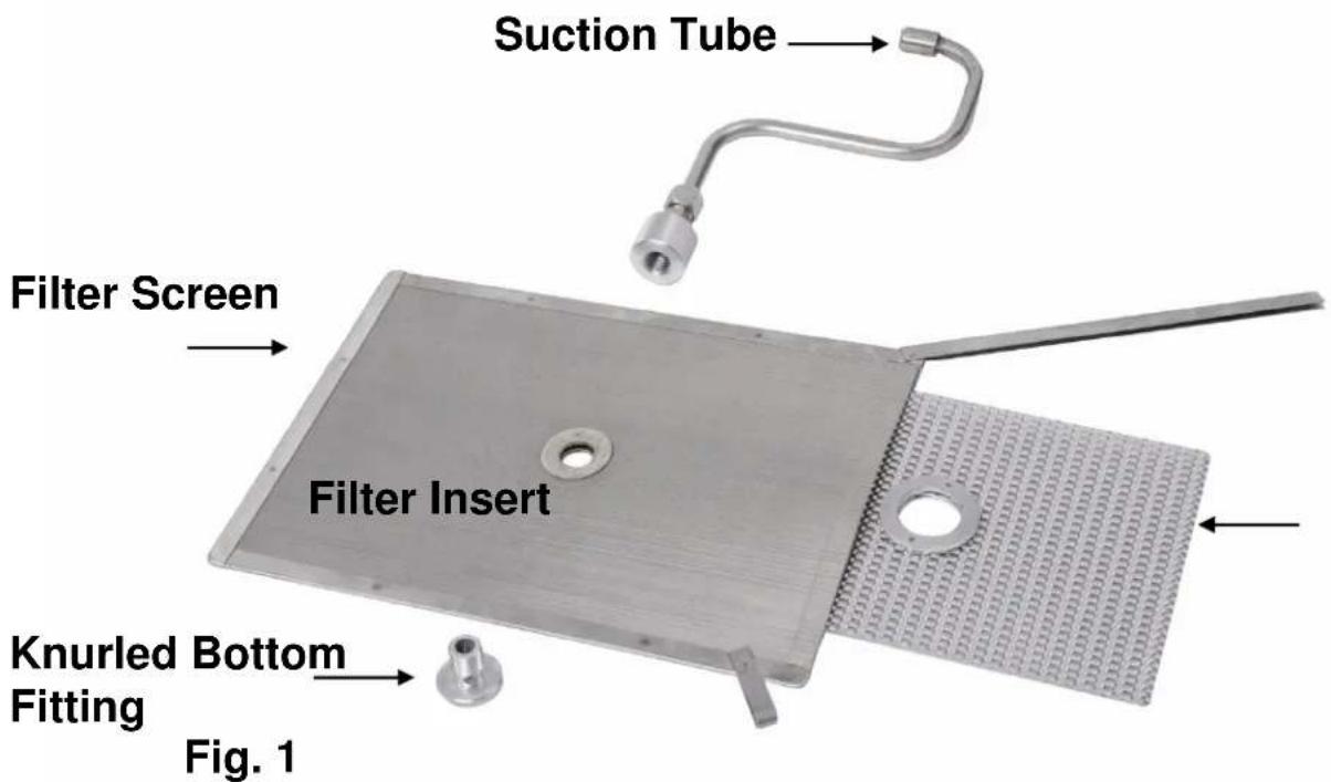
text_image
Suction Tube Filter Screen Filter Insert Knurled Bottom Fitting Fig. 1VK / TR / VFRY SERIES GAS FRYERS
Fully assembled filter screen assembly:
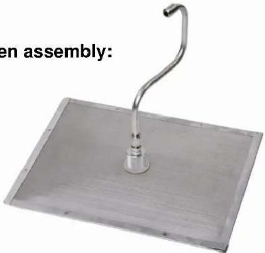
natural_image
Metallic stand with a curved metal hook and central base, labeled 'en assembly:' (no other text or symbols)Fig. 2
Secure Tube with Suction Tube Clip
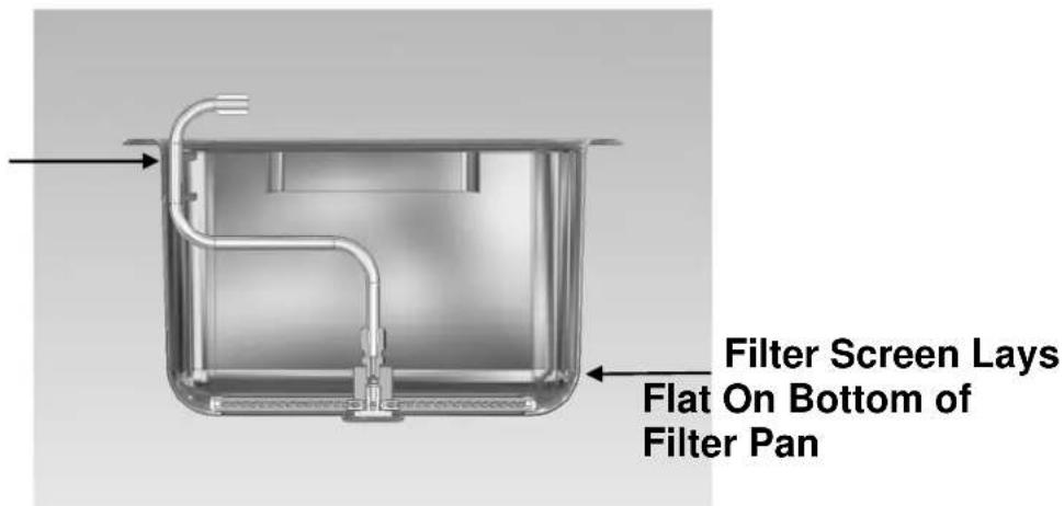
text_image
Filter Screen Lays Flat On Bottom of Filter PanFig. 3

text_image
Micro-Filtration Fabric Envelope Accessory Assembly: Same Suction Tube Fabric Envelope Insert (Different from Screen Assembly) Fabric Envelope Same Knurled Knob Closing Clip Fig. 4VK / TR / VFRY SERIES GAS FRYERS
INSTRUCTIONS TO REMOVE & REPLACE KLEENSCREEN PLUS® FILTER ENVELOPE
FOR ABSOLUTE FILTRATION & MAXIMUM FLOW RATE WE RECOMMEND YOU CHANGE YOUR FILTER ENVELOPES AT EVERY OIL CHANGE (10-14 DAYS DEPENDING ON OIL USAGE).
natural_image
Industrial machine component with red clamps and metallic casing (no visible text or symbols)Step 1
Discard all oil from the filter vessel, (see pages 23 or 24). When the filter pan is empty, use a spatula and scrape off all debris left on the filter envelope and in the filter pan.
natural_image
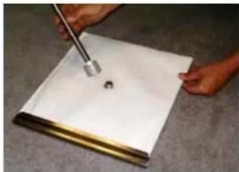
Person using a tool to mark a small hole on a white sheet of paper (no text or symbols visible)Step 2
Unscrew "S" Tube from filter by turning the Bottom Knurled fitting counter-clockwise.
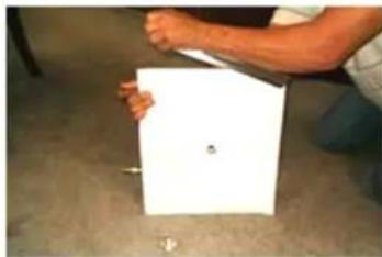
natural_image
Person holding a white rectangular object on a carpet (no visible text or symbols)Step 3
Remove SST Closure Clip by lifting off one side.
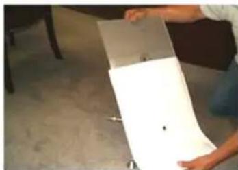
natural_image
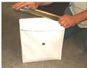
Person holding a white sheet with a small black mark, placed on a gray surface (no text or symbols visible)Step 4
Remove SST Filter Screen Insert and wash insert with hot water and dry thoroughly. The Filter Screen Insert is dishwasher safe. Place the insert into a new KleenScreen PLUS® Filter envelope.
natural_image
Person handling a white object with a metal tool, no visible text or symbolsDO NOT WASH FABRIC ENVELOPE
Step 5
Place Filter Screen Insert into the fabric envelope making sure that the holes line up. Fold over the other end of the envelope and place SST Closure Clip on – hinge over and firmly press clip all the way down to secure and seal filter assembly. Making sure that the folded end is face down; screw "S" Tube Assembly onto the Filter Assembly. Tighten the Bottom Knurled fitting. When tightened, the "S" Tube assembly should be perpendicular to the long side of the filter assembly.
natural_image
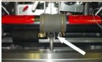
Close-up of a mechanical assembly with red and gray components and a white arrow pointing to a component (no visible text or symbols)Step 6
Reposition the filter tube into the provided clip. Align filter tube so that the end of the "S" Tube engages the Oil Receptacle fitting each time the drawer is opened and closed.
Operation
MOVARYING parts can cause burns. Use care when operating, cleaning and servicing the fryer.
⚠️ Währing got frying compound can cause severe burns. Do not move fryer without draining all frying compound from the tank.
NOTICE Never run water or boil out solution through filter and motor / pump. Doing so will void your fryer warranty.
File NOTICE one fry tank at a time
FILTERING PROCEDURE – KleenScreen PLUS® Models ONLY
Filter shortening at least once a day.
-
NOTICE Do NOT turn off the power to the fryer. Leave power on.
-
Vulcan recommends adding an oil treatment media to the oil prior to filtering.
-
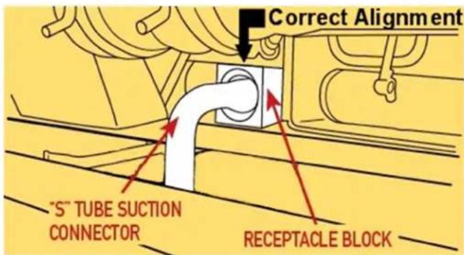
Make sure that the filter drawer is closed completely and that the suction tube and receptacle block are in the correct position. Fig. 5
text_image
Correct Alignment "S" TUBE SUCTION CONNECTOR RECEPTACLE BLOCKFig. 5
-
A cold fryer will not drain easily. Always filter shortening between 250^ F and 350^ F. The shortening in the cold zone area will remain hard if the heat is only on for a few minutes. If necessary, use the clean-out rod to carefully move the hard shortening to an area above the cold zone where it will melt.
-
Slowly open the drain valve to allow oil to flow from the fry tank to the filter pan. Then open the drain valve all the way. Please note the gas power burner will automatically turn off at this point. DRAINING will appear on the digital display for solid state digital (D) and DRAINING OIL will display on computer models (C).
VK / TR / VFRY SERIES GAS FRYERS
- When fry tank is empty turn on the filter pump by pressing the filter button on the (A) control or by holding your finger on the filter icon for 3-4 seconds on the solid state digital models (D) and for computer models (C). Allow the pump to filter the oil for a couple of minutes BEFORE closing the drain valve.
- Close the drain valve. The display will change to; FILL TANK for solid state digital models (D) and FILL TANK for computer models (C).
- Fill tank with new shortening. Fill to a minimum of the MIN level but no higher than halfway between MIN and MAX. Oil will expand as it is heated.
- On solid state digital models (D) and computer models (C) models, the display will ask if the tank is full; TANK FULL, HIT TEMP. If the tank is full, press the Temp Button on the display. Once pressed, the gas power burner will ignite and begin heating the oil to desired temperature.
- Press the START button for solid state knob control (A) and gas power burner with ignite and begin heating the oil.
VULCAN FRYERS SOLID STATE KNOB CONTROLS GUIDE

DONE TO PERFECTION.
FILTERING in 7 Easy Steps
STEPS 1-4
TIP: Use provided crumb scoop to remove and suspend crumbs on the bottom of tank before proceeding to Step 1.
text_image
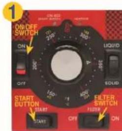
1 ON/OFF SWITCH 200Ω 250Ω 300Ω 350Ω 400Ω 450Ω 500Ω SOLID LICID START BUTTON START START OFF FILTER SWITCH FUSER ONMake sure that the Power is on. Do NOT turn off the power to the fryer
• Vulcan recommends adding an oil treatment media to the oil prior to filtering.
• Make sure that the filter drawer is closed completely and that the suction tube and receptacle block are in the correct position.

text_image
2 Correct Alignment "S-TUBE SUCTION CONNECTOR RECEPTACLE BLOCKOpen the fryer doors and ensure that the filter drawer is pushed back into place under the fryer with the "S" Tube Suction Connector and Receptacle Block engaged.
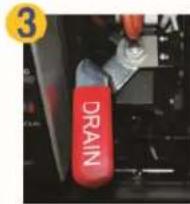
Open the drain valve slowly allowing the oil to drain down into the filter pan. The burners or heating elements will automatically turn off.
TIP: Use the provided tank brush to clean and remove food particles from the fry tank.
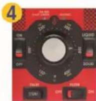
Press FILTER switch to engage the motor/pump. Allow the oil to cycle for a few minutes until the oil and fryer are clean.
STEPS 5-7
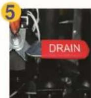
Close the drain valve slowly allowing the oil to fill the fry tank with clean oil. The burners or heating elements will not turn on at this point. Allow the oil to fill back into the fry tank from the filter pan. It is normal to see a few air bubbles during this process.
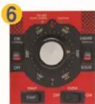
When the filter pan is empty push the FILTER switch to turn off the motor / pump. Oil level should be between the MIN and MAX lines.
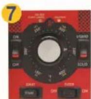
Once the level of the oil has been checked and verified, press the START switch. The red light will turn to green. The burners or heating elements will automatically turn back on and the fryer will recume heating. Yellow light will display when heating.
DRAINING AND DISCARDING OIL FROM THE FRYER
A Follow filtering instructions steps 2 - 3, however DO NOT put oil treatment media into fryer. Drain the fryer oil into the filter pan.
B Attach the quick disconnect hose to the discard male quick disconnect fitting. Do not connect hose while motor/pump is running.
C Place other end of the discard hose into a container that is large enough to retain the discarded shortening.
D To start the discard operation, filter switch behind door must be in the "use hose to discard only" position.
E Before pressing the FILTER button located behind the door, hold the hose firmly and point to the discard container. Press the FILTER button and the motor/pump will start immediately. Oil will begin to flow through the hose into the container.
F To turn off the motor/pump, simply push the FILTER button on the control again. Push the filter switch behind the door back to the "use hose to rinse & fill" position. Disconnect the discard hose. Be careful to let the hose drain before putting away. Close the drain valve and refill the fry tank with new oil.
NOTICE If discard vessel is not large enough to hold the entire shortening amount, stop the flow by pushing the FILTER button to turn the motor/pump off. Empty the container and resume discard operation by pushing the FILTER button and holding it for approximately 3 seconds.
NOTICE Open the filtering drawer approximately 1" to allow any oil in the return line to run back into the filter pan. This will take about 30 seconds to complete. Then open the drawer completely to clean filter components. THESE INSTRUCTIONS ARE FOR FRYERS WITHOUT REAR OIL RECLAMATION CONNECTIONS.
⚠ WARNING
HOT FRYING COMPOUND AND PARTS CAN CAUSE BURNS. USE CARE WHEN OPERATING, CLEANING, OR SERVICING THE FRYER. USE CARE WHEN FILTERING. DO NOT LEAVE UNATTENDED.
SPILLING HOT FRYING COMPOUND CAN CAUSE SEVERE BURNS. DO NOT MOVE THE FRYER WITHOUT FIRST DRAINING ALL FRYING COMPOUND FROM TANK.
NOTICE IF POWER IS MISTAKENLY TURNED OFF DURING THE FILTERING OPERATION, THE CORRECTIVE ACTION IS AS FOLLOWS:
- CLOSE DRAIN VALVE
- TURN POWER SWITCH ON
- IMMEDIATELY OPEN DRAIN VALVE
- CONTINUE FILTERING OPERATION PER STEPS 1-7
NOTICE NOT RECOMMENDED TO BE USED WITH SOLID SHORTENING.
Filtering Instructions for Solid State Controls
VULCAN FRYERS

SOLID STATE CONTROLS GUIDE

DONE TO PERFECTION.
FILTERING in 7 Easy Steps (for revisions V4.00 or higher)
STEPS 1-3
TIP: Use provided crumb scoop to remove and suspend crumbs on the bottom of tank before proceeding to Step 1.
text_image
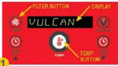
FILTER BUTTON VULCAN DISPLAY TEMP. BUTTONMake sure that the Power Switch is in the "ON" position.
Fryer must have power to operate the motor/pump. Fryer Temperature should be between 300-350 Degrees Fahrenheit. RECOMMENDED: ADD OIL TREATMENT MEDIA.
text_image
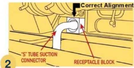
Correct Alignment "S" TUBE SUCTION CONNECTOR RECEPTACLE BLOCKOpen the fryer doors and ensure that the filter drawer is pushed back into place under the fryer with the "S" Tube Suction Connector and Receptacle Block engaged.
STEPS 4-7
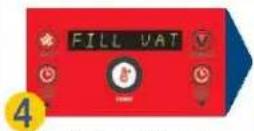
When filtering is finished, close the red drain valve by turning the red drain handle. FILL VAT displays.
- Turn the drain valve to allow the oil to drain into the filter pan below. The burners will automatically turn off.
- While draining the tank, use the provided tank brush to move the residue at the bottom and sides of the tank down into drain tube.
- To turn on the filter motor/pump, push the FILTER button located on the control panel, holding it for approximately 3 seconds.
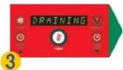
- Allow the oil to cycle through the filtering operation for about 3 minutes or until satisfied that the oil and dry tank are clean. DRAINING displays.
TIP: Use provided tank brush to clean and remove food particles on the dry tank
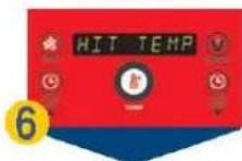
Once the oil level has been checked and verified, press the TEMP button. The burners will automatically turn back on and the tryer will resume heating. HIT TEMP displays.
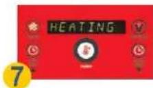
After pressing the TEMP button the fryer resumes heating. HEATING displays.
DRAINING AND DISCARDING OIL FROM THE FRYER
A Follow filtering instructions steps 2 - 4, however DO NOT put oil treatment media into layer. Drain the layer oil into the filler pan
B Attach the quick disconnect hose to the discard male quick disconnect fitting. Do not connect hose while motor/pump is running.
C Place other end of the discard hose into a container that is large enough to return the discarded shortening
D To start the discard operation, filter switch behind door must be in the "use hose to discard only" position
YOU MUST USE THE FILTER BUTTON ON THE DIGITAL CONTROL TO DISCARD THE OIL. Press the FILTER button on the digital control and hold for approximately 3 seconds to activate the motorburn. Oil will begin to flow through the hose and into the container. PLEASE NOTE that the display will not change for this operation.
E To turn off the motor/pump, simply push the FILTER button on the digital control again. Push the filter switch behind door back to the "use hose to rinse & fill" position. Disconnect the discard hose. Be careful to let the hose drain before putting away. Close the drain valve and roll the fry tank with new oil
WARNING: Hose connection will be HOT. Use protective heat resistant gloves when handling.
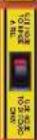
NOTE: If discard vessel is not large enough to hold the entire showering amount, stop the flow by pushing the FILTER button to turn the motor/pump off. Employ the container and resume discard operation by pushing the FILTER button and holding it for approximately 5 seconds. THESE INSTRUCTIONS ARE FOR FRYERS WITHOUT REAR OIL RECLAMATION CONNECTIONS.
NOTICE Open the filtering drawer approximately 1" to allow any oil in the return line to run back into the filter pan. This will take about 30 seconds to complete. Then open the drawer completely to clean filter components. THESE INSTRUCTIONS ARE FOR FRYERS WITHOUT REAR OIL RECLAMATION CONNECTIONS.
WARNING
HOT FRYING, COMPOUND AND PARTS CAN CAUSE BURNS. USE CARE WHEN OPERATING CLEANING, OR SERVICING THE FRYER. USE CARE WHEN FILTERING. DO NOT LEAVE UNATTENDED.
SPILLING HOT FRYING COMPOUND CAN
CAUSE SEVERE BURNS. DO NOT MOVE THE FRYER
WITHOUT FIRST DRAINING ALL FRYING COMPOUND
FROM TANK.
IMPORTANT:
IF POWER IS MISTAKENLY TURNED OFF DURING THE FILTERING OPERATION, THE CORRECTIVE ACTION IS AS FOLLOWS.
- CLOSE DRAIN VALVE
2 TURN POWER SWITCH ON - IMMEDIATELY OPEN DRAIN VALVE
4 CONTINUE FILTERING OPERATION PER STEPS 1-5
NOTE: NOT RECOMMENDED TO BE USED WITH SOLID SHORTENING
VULCAN FRYERS
COMPUTER CONTROLS GUIDE


DONE TO PERFECTION.
FILTERING in 6 Easy Steps (for revisions V2.79 or higher)
STEPS 1-3
TIP: Use provided crumb scoop to remove and suspend crumbs on the bottom of tank before proceeding to Step 1.
TEMPERATURE BUTTON
PROGRAM BUTTON
RED LED LIGHT
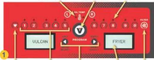
text_image
UULTEMP 1 2 3 4 5 V PROGRAM FRYER FILTER UULCAN MELK MELK MELKTOGGLE BUTTON
MENI ITEMS
LEFT & RIGHT ARROW KEYS
DISPLAY
FILTER BUTTON
Make sure that the Power Switch is in the "ON" position. Fryer must have power to operate the motor/pump. Fryer Temperature should be between 300-350 Degrees Fahrenheit. RECOMMENDED: ADD OIL TREATMENT MEDIA.
text_image
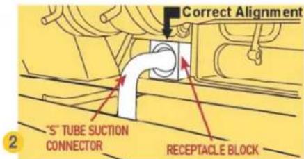
Correct Alignment "S" TUBE SUCTION CONNECTOR RECEPTACLE BLOCKOpen the fryer doors and ensure that the filter drawer is pushed back into place under the fryer with the "S" Tube Suction Connector and Receptacle Block engaged. Filter switch behind the door must be in the filter position (not on hose).
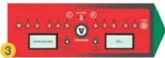
TIPS: Use provided tank brush to clean and remove food particles on the fry tank. Use provided clean-out rod to clear drain if clogging occurs.
- Turn the drain valve to allow the oil to drain into the filter pan below. The fryer will automatically turn off.
- While draining the tank, use a crumb scoop to move the residue at the bottom and sides of the tank down into drain tube.
- To turn on the filter motor/pump, push the FILTER button located on the control panel, holding it for approximately 3 seconds.
- Allow the oil to cycle through the filtering operation for about 3 minutes or until satisfied that the oil and fry tank are clean. DRAINING OIL displays.
STEPS
4-6

- When filtering is finished, close the red drain valve by turning the red drain handle. FILL VAT displays.
- Allow all of the oil to flow back into the fryer from the filter pan. It is normal to see air bubbles in the tank toward the end of filtering.
FILTER
©
(※)
mio
- When the filter pan is empty, push the FILTER button to turn off the motor/pump.
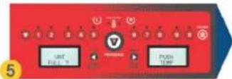
- Oil level should be between the Min/Max lines on the tank back. VAT FULL ? PUSH TEMP displays. (Display is asking if the tank is full.)
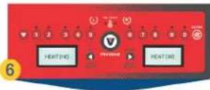
Once the oil level has been checked and verified, press the OIL TEMP button. The fryer will automatically turn back on and the fryer will resume heating. HEATING displays if oil temperature is below set temperature.
DRAINING AND DISCARDING OIL FROM THE FRYER
A Follow filtering instructions steps 2 - 4, however DO NOT put oil treatment media into fryer. Drain the fryer oil into the filter pan.

B Attach the quick disconnect hose to the discard male quick disconnect fitting. Do not connect hose while motor/pump is running.
Place other end of the discard hose into a container that is large enough to retain the discarded shortening.
D To start the discard operation, filter switch behind door must be in the "use hose to discard only" position
YOU MUST USE THE FILTER BUTTON ON THE COMPUTER CONTROL TO DISCARD THE OIL. Press the FILTER button on the computer control and hold for approximately 3 seconds to activate the motor/pump. Oil will begin to flow through the hose and into the container. PLEASE NOTE that the display will not change for this operation.
E To turn off the motor/pump, simply push the FILTER button on the computer control again. Push the filter switch behind door back to the "use hose to rinse & fill" position. Disconnect the discard hose. Be careful to let the hose drain before putting away. Close the drain valve and refill the fry tank with new oil.
WARNING Hose connection will be HOT. Use protective heat resistant gloves when handling,
NOTE: If discard vessel is not large enough to hold the entire shortening amount, stop the flow by pushing the FILTER button to turn the motor/pump off. Empty the container and resume discard operation by pushing the FILTER button and holding it for approximately 3 seconds. THESE INSTRUCTIONS ARE FOR FRYERS WITHOUT REAR OIL RECLAMATION CONNECTIONS
NOTICE Open the filtering drawer approximately 1" to allow any oil in the return line to run back into the filter pan. This will take about 30 seconds to complete. Then open the drawer completely to clean filter components. THESE INSTRUCTIONS ARE FOR FRYERS WITHOUT REAR OIL RECLAMATION CONNECTIONS..
F32980 (October 2016)
▲WARNING
HOT FRYING COMPOUND AND PARTS CAN CAUSE BURNS. USE CARE WHEN OPERATING, CLEANING, OR SERVICING THE FRYER. USE CARE WHEN FILTERING. DO NOT LEAVE UNATTENDED.
SPILLING HOT FRYING COMPOUND CAN
CAUSE SEVERE BURNS: DO NOT MOVE THE FRYER
WITHOUT FIRST DRAINING ALL FRYING COMPOUND
FROM JANK.
IMPORTANT:
IF POWER IS MISTAKENLY TURNED OFF DURING THE FILTERING OPERATION, THE CORRECTIVE ACTION IS AS FOLLOWS:
- CLOSE DRAIN VALVE
- TURN POWER SWITCH ON
- IMMEDIATELY OPEN DRAIN VALVE
- CONTINUE FILTERING OPERATION PER STEPS 1-6
NOTE: NOT RECOMMENDED TO BE USED WITH SOLID SHORTENING.
www.vulcanequipment.com • Fryer Technical Support: 1-800-814-2028
WARNING
Hot oil and hot parts can cause burns.
NOTICE
Never run water or boil out solution through filter and motor / pump. Doing so will void your
fryer warranty.
FILTERING TIP:
Open the filtering drawer approximately 1" to allow any oil in the return line to run back into the filter pan. This will take about 30 seconds to complete. Then open the drawer completely to clean filter components.
REMOVING EXCESS DEBRIS FROM THE SCREEN FILTER:
-
Pull the filter drawer out.
-
Remove the filter screen assembly. Scrape debris from the filter screen. Then remove the insert by unlatching the latch. Clean all parts thoroughly as mentioned in the assembly section on page 19.
-
Scrape debris from the bottom of the filter pan and discard in the trash. Clean all parts thoroughly as mentioned in the Assembly section on page 19. Clean all parts thoroughly as mentioned in the Assembly section on page 19.
-
Reassemble all filter components after being dried thoroughly as in the assembly section on page 19.
FLUSH/RINSE AND DISCARD OIL:
-
Follow filtering instructions 1-3, however do not put oil treatment media into the fryer. Drain the fryer oil into the filter pan.
-
Attach the quick disconnect hose to the discard male quick disconnect fitting,
-
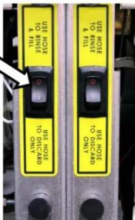
To discard the oil, place the nozzle end of the discard hose into a container that is large enough to retain the discarded shortening. Press the filter switch behind the door to the "USE HOSE TO DISCARD ONLY" position. This will allow all of the oil to be pumped through the hose only.
-
For flushing/rinsing the tank with filtered oil to remove the particulates that have accumulated, press the filter switch behind the door to the "USE HOSE TO RINSE AND FILL" position. This will allow the oil to pass through the hose and come in from behind the tank at the same time.
-
With the power switch still ON; press the discard/flush switch on. Press and hold the filter button for at least 3 seconds and the Motor/Pump will begin to operate. NOTE: Oil will exit immediately out of the nozzle end of the hose.
-
Once the oil has been discarded completely and the filter pan is empty, press the filter button to turn off the Motor/ Pump. Then press the discard/flush switch off.
text_image
USE HOSE TO RINSE & FILL USE HOSE TO DISCARD ONLY USE HOSE TO RINSE & FILL USE HOSE TO DISCARD ONLY- Disconnect the discard hose. The hose connection will be hot due to the temperature of the oil that was discarded. Be careful to let the hose drain before putting away. Close the drain valve and fill the fry tank with new oil.
BOIL OUT PROCEDURE:
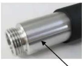
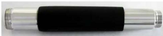
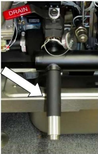
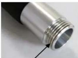
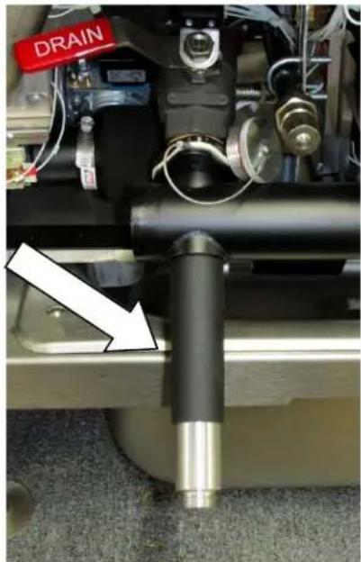
Use the Boil Out By-Pass™ drain extension allowing the boil out solution to exit the fry tank without using the filtering system. Do NOT allow water to run through the motor / pump. Drain the boil out solution into a bucket or place a high temperature rated water hose on the end of the drain extension allowing the other end to flow into a floor drain. In Fig. 6 the arrow is pointing to the drain extension. It is threaded into the top coupling of the oil drain tube. Drain extension needs to be only hand tightened.
natural_image
Close-up of a cylindrical mechanical component with black central body and metallic ends (no visible text or symbols)Boil Out By-Pass™ Extension Tube
natural_image
Close-up of a mechanical assembly with a labeled drain component and a white arrow pointing to a black cylindrical part (no readable text or symbols)Fig. 6

natural_image
Close-up of a metallic cylindrical component with threaded shaft and black handle, showing an arrow pointing to a feature (no text or symbols visible)Standard Hose End (Smaller Thread Side) Drain Tube End (Larger Size Threads)
natural_image
Close-up of a metallic cylindrical object with threaded end and black handle, no visible text or symbolsTHERMAL OVERLOAD PROTECTION BUTTON:
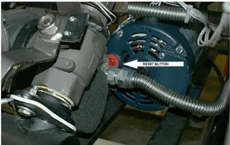
The motor/pump supplied with the filtering system has a thermal overload protection circuit that senses when excess heat occurs. This can occur due to filtering for long periods of time or under heavy load prior to discarding debris buildup. If the thermal overload protection is tripped, wait 5 minutes and then reset the motor by pushing in the red button. The arrow in Figure 7 shows the location of the reset button; located on the front of the motor / pump facing towards you.
⚠ WARNING Hot oil and hot parts can cause burns.
text_image
RESET BUTTONFig 7.
MAINTENANCE
⚠ WARNING and hot parts can cause burns. Use care when operating, cleaning, and servicing the fryer.
⚠️ WARNING hot fryer compound can cause severe burns. Do not move fryer without draining all frying compound from the tank.
FLUE VENT INSPECTION
When the fryer is cool, inspect annually. Check the flue and clear any obstructions.
Service in the US and Canada
Contact the Service Contractor in your area to obtain service and parts information. For a complete listing of Service and Parts depots refer to www.vulcanequipment.com.
ALARMS AND ERROR MESSAGES
NO OR LOW GAS SUPPLY – If no action is taken after 90 seconds, an alarm sounds continuously, the heat demand is disabled and any running cooking cycles are cancelled. The digital display the following message:
“D” Solid State – IGNITION LOCKOUT
"C" Computer – IGNITION LOCKOUT CHECK GAS SUPPLY
The fryer must be turned off, then back on to re-initialize the control and to have normal functions resumed.
OPEN PROBE – If an open probe is detected, the heat demand is disabled and any running cooking cycles are cancelled. All operator buttons are disabled. The digital control displays the following message:
“D” Solid State – OPEN PROBE
"C" Computer – PROBE OPEN
SHORTED PROBE – If a shorted probe is detected, the heat demand is disabled and any running cooking cycles are cancelled. All operator buttons are disabled. The digital control displays the following message:
“D” Solid State – SHORTED PROBE
"C" Computer – PROBE SHORT
Hi TEMPERATURE – If the temperature is greater than or equal to 415^ F ( 212^ C), the heat demand is disabled and any running cooking cycles are cancelled. All operator buttons are disabled. The control displays the following message:
“D” Solid State – HIGH TEMP
"C" Computer – HIGH TMP HIGH TMP
| Troubleshooting Chart: | |
| Problem: Probable Cause: | |
| No Heat: Power switch not turned on. Gas supply not turned on. Wire connections loose (call service) Wires connections need cleaning High Limit (call service) | |
| Insufficient or too much heat: Temperature not set to desired temperature. High limit tripped (call service) Temperature probe (call service) | |
| Tank will not drain: Shortening too cold. Drain pipe clogged with debris. | |
| Motor / pump will not pump oil: Suction tube not seated correctly in receptacle block. Filter screen is clogged and needs cleaning. Shortening is too thick / cold. Heat oil up to min. 300° F. Discard valve lever not fully engaged either for filtering or discarding. Thermal overload protection button tripped. | |
GUIDE D'INSTALLATION ET D'UTILISATION
natural_image
Exterior view of a Power Fry air fryer with red control panel and wheels (no visible text or symbols on device body)1VK45C illustré
MODÈLES :
| 1VK45 | 1TR45 | |
| 1VK65 | 1TR65 | |
| 1VK85 | 1TR85 | |
| 2VK45 | 2TR45 | |
| 2VK65 | 2TR65 | |
| 2VK85 | 2TR85 | |
| 3VK45 | 3TR45 | |
| 3VK65 | 3TR65 | |
| 3VK85 | 3TR85 | |
| 4VK45 | 4TR45 | |
| 4VK65 | 4TR65 | |
| 4VK85 | 4TR85 | |
| 5VK45 | 5TR45 | |
| 5VK65 | 5TR65 | |
| 5VK85 | 5TR85 | |
| 6VK45 | 6TR45 | |
| 6VK65 | 6TR65 | |
| 6VK85 | 6TR85 | |
| 2MB | VFRY18 | |
| 3MB | ||
| 4MB | ||
| 5MB | ||
| 6MB |
text_image
ACT 340F TRI/ULAN SET 340Fnatural_image
Close-up of a mechanical assembly with red and metallic components, no visible text or symbolsÉtape 1
natural_image
Close-up of hands using a tool to apply material to a white sheet with a small hole (no text or symbols visible)Étape 2
natural_image
Person holding a white rectangular object on a floor, no visible text or symbolsÉtape 3
natural_image
Person holding a white sheet with a small black mark, placed on a gray surface (no text or symbols visible)Étape 4
natural_image
Person handling a white rectangular object with a metallic rod, no visible text or symbolsNE PAS LAVER L'ENVELOPPE EN TISSU
Étape 5
natural_image
Close-up of a mechanical assembly with red and gray components and a white arrow pointing to a component (no visible text or symbols)Étape 6
text_image
ON/OFF START/RESET OFF/RESET ON/OFF START/RESET OFF/RESET ON/OFF SOLID ON/OFF START/RESET OFF/RESET ON/OFF SOLID ON/OFF ON/OFF ON/OFF ON/OFF ON/OFF ON/OFF ON/OFF ON/OFF ON/OFF ON/OFF ON/OFF ON/OFF ON/OFF ON/OFF ON/OFF ON/OFF ON/OFF ON/OFF ON/OFF ON/OFF ON/OFF ON/OFF ON/OFF ON/OFF ON/OFF ON/OFOF ON/OFOF ON/OFOF ON/OFOF ON/OFOF ON/OFOF ON/OFOF ON/OFOF ON/OFOF ON/OFOF ON/OFOF ON/OFOF ON/OFOF ON/OFOF ON/OFOF ON/OFOF ON/OFOF ON/OFOF ON/OFOF ON/OFOF ON/OFOOFC ON/OFOOFC ON/OFOOFC ON/OFOOFC ON/OFOOFC ON/OFOOFC ON/OFOOFC ON/OFOOFC ON/OFOOFC ON/OFOOFC ON/OFOOFC ON/OFOOFC ON/OFOOFC ON/OFOOFC ON/OFOOFC ON/OFOOFC ON/OFOOFC ON/OFAOFC ON/OFAOFC ON/OFAOFC ON/OFAOFC ON/OFAOFC ON/OFAOFC ON/OFAOFC ON/OFAOFC ON/OFAOFC ON/OFAOFC ON/SOLIDnatural_image
Close-up of a cylindrical mechanical component with black end caps and metallic shaft (no visible text or symbols)Tube de rallonge Boil Out By-Pass™
natural_image
Close-up of a mechanical assembly with a black cylindrical component and a red 'DRAIN' label, no readable text or symbols beyond the label.Fig. 6