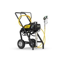
ProSpray 3.31 Connect - Paint gun WAGNER - Free user manual and instructions
Find the device manual for free ProSpray 3.31 Connect WAGNER in PDF.


| Product type | High-pressure airless paint sprayer |
| Brand | WAGNER |
| Model | ProSpray 3.31 Connect |
| Dimensions (L × D × H) | 590 × 529 × 726 mm |
| Weight | 43.5 kg |
| Power supply | 220-240 V AC, 50/60 Hz |
| Power consumption | 1840 W |
| Max current | 8.0 A |
| Max working pressure | 221 bar (22.1 MPa) |
| Flow rate at 120 bar (water) | 3.8 L/min |
| Max nozzle orifice | 0.032 in (0.81 mm) |
| Max material viscosity | 25 000 mPa·s |
| Max material temperature | 43 °C |
| High-pressure hose | DN 6 mm, 15 m, M16×1.5 connection |
| Connectivity | Bluetooth 2.4 GHz (range ~10 m) |
| Smart features | SprayManager app (Android/iOS): nozzle/dilution recommendations, remote pressure adjustment, wear tracking, project planning |
| Control screen | Digital Electronic Spray Control (DESC) with display and buttons |
| Max noise level | 80 dB (at 1 m, 120 bar) |
| Vibrations (gun) | < 2.5 m/s² |
| Maintenance | Clean after each use; EasyGlide oil change every 8 h; clean filter regularly; annual service recommended |
| Warranty | 3 years (extend to 5 years after registration within 28 days) |
| Areas of use | Indoors only; paints, lacquers, varnishes, dispersions, anti-corrosion products, etc. |
Frequently Asked Questions - ProSpray 3.31 Connect WAGNER
User questions about ProSpray 3.31 Connect WAGNER
0 question about this device. Answer the ones you know or ask your own.
Ask a new question about this device
Download the instructions for your Paint gun in PDF format for free! Find your manual ProSpray 3.31 Connect - WAGNER and take your electronic device back in hand. On this page are published all the documents necessary for the use of your device. ProSpray 3.31 Connect by WAGNER.
USER MANUAL ProSpray 3.31 Connect WAGNER
natural_image
Line drawing of a pressure pump with attached motor and wheels (no text or symbols)PROSPRAY 3.31 CONNECT
BETRIEBSANLEITUNG • OWNER'S MANUAL MODE D'EMPLOI • ISTRUZIONE PER L'USO



https://spraymanager.io
DE WAGNER SprayManager App\*
With the free "SprayManager" app from WAGNER, you can establish a Bluetooth connection to your device to benefit from the following convenient functions:
- Scan the material to be processed ("Scan the Can") and you will get recommendations for the dilution and nozzle.
- The spray device automatically adjusts to the pressure recommended by the material manufacturer.
- Live information on material pressure, operating time and the amount of material processed while working.
- Setting the pressure by remote control.
- Up-to-date information on nozzle wear and the necessary service intervals.
- Planning of new projects and an overview of started and completed projects.
* Android from version 7, iOS from version 13
FR App WAGNER SprayManager\*
11 REPARATUREN AM GERÄT 21
2.2 EXPLOSIONSSCHUTZ

https://go.wagner-group.com/technology
3.6 TRANSPORT
3.7 TRANSPORT IM FAHRZEUG
Das Menüfenster Volume Pumped
Menüfensters Volume Pumped
Menüfensters Unit Serial #
natural_image
Diagram of a mechanical component with a rotating arrow indicating rotation (no text or symbols)8.3 HOCHDRUCKFILTER REINIGEN

11 REPARATUREN AM GERÄT
natural_image
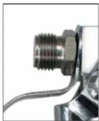
Close-up of a mechanical component with threaded shaft and metallic housing (no visible text or symbols)G-Gewinde (7/8")
natural_image
Close-up of a metallic mechanical component with threaded end and coiled cable (no visible text or symbols)F-Gewinde (11/16")
natural_image
Illustration of a robotic device with a checkmark symbol (no text or labels present)natural_image
Line drawing of a handheld industrial control device with coiled tubing and connector (no text or symbols)TempSpray H 226 / H 326
natural_image
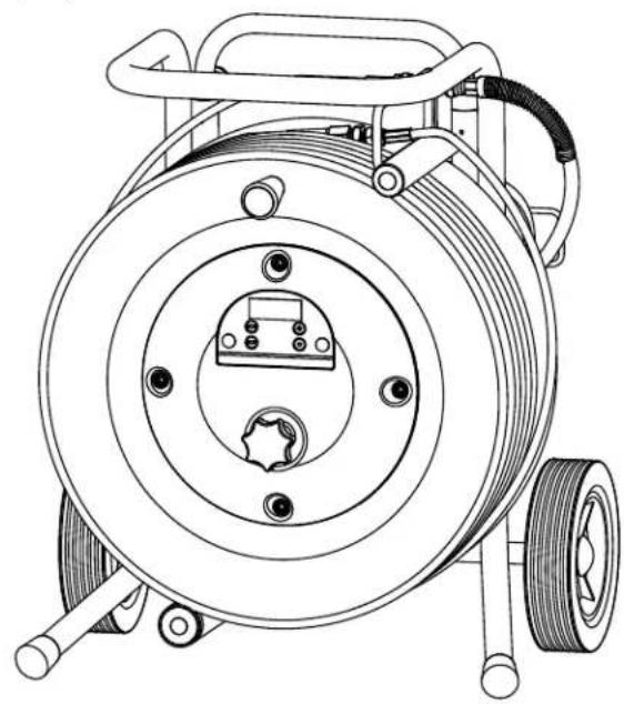
Technical line drawing of a mechanical pump or reel assembly with coiled cable and mounting feet (no text or symbols)12.5 PUMP-RUNNER
(Best. Nr. 2306987)
natural_image
Line drawing of a mechanical component with threaded base and mounting bracket (no text or symbols)
natural_image
Technical line drawing of a mechanical component with threaded base and two protruding pipes (no text or symbols)PRÜFUNG DES GERÄTES
https://go.wagner-group.com/pf-warranty-conditions

Translation of the original operating manual
1 GENERAL SAFETY INSTRUCTIONS 29
2 SAFETY REGULATIONS FOR AIRLESS SPRAYING 30
3 GENERAL VIEW OF APPLICATION 33
3.1 Application 33
3.2 Coating materials 33
3.3 Technical data 34
3.4 Legend for explanatory diagram PS 3.31 ____ 35
3.5 Explanatory diagram PS 3.31 35
3.6 Transportation 36
3.7 Transportation in vehicle 36
4.1 High-pressure hose, spray gun and separating oil _ 36
4.2 Control panel indicators 37
4.3 Pressure control knob settings ____ 37
4.4 Connection to the mains network 38
4.5 Cleaning preserving agent when starting-up of operation initially ____ 38
4.6 Taking the unit into operation with coating material 38
4.7 Digital Electronic Spray Control (DESC) 39
5 SPRAYING TECHNIQUE 41
6 HANDLING THE HIGH-PRESSURE HOSE \_\_\_\_ 41
7 INTERRUPTION OF WORK 42
8 CLEANING THE UNIT (SHUTTING DOWN) \_ 42
8.1 Cleaning unit from outside 42
8.2 Suction filter 43
8.3 Cleaning the high-pressure filter 43
8.4 Cleaning Airless spray gun 43
9 REMEDY IN CASE OF FAULTS 45
10 SERVICING 46
10.1 General servicing 46
10.2 High-pressure hose 46
11 REPAIRS AT THE UNIT 46
11.1 Inlet and outlet valve 46
11.2 Digital Electronic Spray Control (DESC)
Error Messages 56
12 APPENDIX 48
12.1 Selection of tip 48
12.2 Servicing and cleaning of Airless hard-metal tips ____48
12.3 Spray gun accessories 48
12.4 TempSpray 50
12.5 Pump-Runner 51
IMPORTANT NOTES ON PRODUCT LIABILITY \_\_\_\_ 52
3+2 YEARS GUARANTEE FOR PROFESSIONAL FINISHING 52
ACCESSORIES FOR PROSPRAY 3.31 104
Spare parts list for main assembly 106
Spare parts list of filter assembly 108
Spare parts list of cart assembly 110
SALES AND SERVICE COMPANIES 112
1 GENERAL SAFETY INSTRUCTIONS
WARNING!
Read all safety information, instructions, illustrations and technical data provided with this power tool. Failure to observe the following instructions may cause electric shock, fire and/or severe injuries. Keep all safety information and instructions for future reference. The term "power tool" used in this safety information refers to mains-operated power tools (with power cable) and to battery-powered power tools (without power cable).
1. Safety at the workplace
a) Keep your workplace clean and well lit. Disorder or unlit workplaces may result in accidents.
b) Do not work with the power tool in potentially explosive environments where there are flammable fluids, gases or dust. Power tools generate sparks that can ignite the dust or vapors.
c) Keep children and other persons away when using the power tool. If distracted, you may lose control of the power tool.
2. Electrical Safety
a) The connection plug of the power tool must fit in the socket. The plug may not be modified in any form. Verwenden Sie keine Adapterstecker gemeinsam mit schutzgeerdeten Elektrowerkzeugen. Unmodified plugs and suitable sockets reduce the risk of an electric shock.
b) Avoid physical contact with earthed surfaces such as pipes, heating elements, stoves and refrigerators. The risk through electric shock increases if your body is earthed.
c) Keep power tools away from rain or moisture. Water penetrating into a power tool increases the risk of an electric shock.
d) Do not misuse the power cord to carry the power tool, hang up the power tool or pull the plug out of the socket. Keep the power cord away from heat, oil, sharp edges or moving parts. Damaged or entangled power cords increase the risk of an electric shock.
e) If the power tool must be used in a moist environment, use a ground fault circuit interrupter. Using a residual current operated circuit-breaker avoids the risk of electric shock.
3. Safety of Persons
a) Be attentive. Pay attention to what you are doing and work sensibly with a power tool. Do not use the power tool if you are tired or under the influence of drugs, alcohol or medication. One moment of carelessness when using the power tool may cause serious injuries.
b) Wear personal safety equipment and always wear safety goggles Wearing personal protective equipment, such as dust mask, non-slip safety shoes, safety helm or ear protection, depending on the type of power tools, reduces the risk of injury.
c) Avoid accidental starting-up. Make sure that the power tool is switched off before you connect it to the power tool and/or battery, pick it up or carry it. Accidents may happen if you have your finger on the switch while carrying the power tool or if the device is switched on when you connect it to the power supply.
d) Remove setting tools or wrenches before switching on the power tool. A tool or key in a rotating part of the power tool can cause injuries.
e) Avoid an unnatural posture. Ensure that you are standing securely and have your balance at all times. This allows you can better control the power tool in unexpected situations.
f) Wear suitable clothing. Do not wear wide clothing or jewellery. Keep your hair, clothes and gloves away from moving parts. Loose clothing, jewellery or long hair can be caught in moving parts.
g) Do not lull yourself into a false sense of security and do not think yourself above the safety rules for electric tools, even if you are familiar with the electric tool following extensive practical experience. Careless use can lead to serious injuries in fractions of a second.
4. Usage and treatment of the electric tool
a) Do not overload the power tool. Use the power tool designed for the work that you are doing. You work better and safer in the specified performance range if you use the suitable power tool.
b) Do not use power tools whose switch is defective. A power tool that cannot be switched on or off is dangerous and has to be repaired.
c) Disconnect the plug from the socket and/or take out a removable battery before you make device adjustments, change accessories or put the power tool away. This precautionary measure prevents the power tool from starting unintentionally.
d) Store unused power tools so that they are inaccessible to children. Do not let persons use the tool who are not familiar with it or who have not read these instructions. Power tools are dangerous when they are used by inexperienced persons.
e) Maintain the power tool and insertion tools with care. Check whether moving device parts are working flawlessly and are not jamming, whether parts are broken or damaged so that as to impair the function of the power tool. Have damaged parts repaired before using the power tool. Many accidents have their origin in
power tools that have been maintained badly.
f) Use the power tool, accessories, insert tools, etc. in accordance with these instructions and in a fashion specified for this special tool type. Take the working conditions and the activity to be carried out into consideration. The use of power tools for purposes other than the intended ones can lead to dangerous situations.
g) Keep the handles and grip surfaces dry, clean and free of oil and grease. Slippery handles and grip surfaces hamper safe operation and control of the electric tool in unforeseen situations.
5. Service
a) Only have your power tool repaired by a qualified specialist and only use original spare parts. This ensures that the tool safety is maintained.
b) If the supply cord is damaged, it must be replaced by the manufacturer or it's service agent or a similarly qualified person in order to avoid a safety hazard.
2 SAFETY REGULATIONS FOR AIRLESS SPRAYING
All local safety regulations in force must be observed. The following safety regulations are to be observed in order to ensure safe handling of the Airless high-pressure spraying unit.
2.1 FLASH POINT

Only spray coating materials with a flash point of 21^ C or higher.
The flash point is the lowest temperature at which vapors develop from the coating material. These vapors are sufficient to form an inflammable mixture over the air above the coating material.
2.2 EXPLOSION PROTECTION

Do not use the unit in work places which are covered by the explosion protection regulations. The unit is not designed to be explosion protected. Do not operate the device in explosive areas (zone 0, 1 and 2). Explosive areas are, for example, places where paints are stored and locations in direct proximity to the object being sprayed. Keep the device at least 3 m from the object you are spraying.
2.3 DANGER OF EXPLOSION AND FIRE FROM SOURCES OF IGNITION DURING SPRAYING WORK

There must be no sources of ignition such as, for example, open fires, lit cigarettes, cigars or tobacco pipes, sparks, glowing wires, hot surfaces, etc. in the vicinity.
2.4 DANGER OF INJURY FROM THE SPRAY JET

Attention, danger of injury by injection! Never point the spray gun at yourself, other persons or animals.
Only use the spray gun with spray jet touch protection.

The spray jet must not come into contact with any part of the body.
In working with Airless spray guns, the high spray pressures arising can cause very dangerous injuries. If contact is made with the spray jet, coating material can be injected into the skin. Do not treat a spray injury as a harmless cut. In case of injury to the skin by coating material or solvents, consult a doctor for quick and correct treatment. Inform the doctor about the coating material or solvent used.
Always secure the spray gun when mounting or dismounting the tip and in case of interruption to work.
2.6 RECOIL OF SPRAY GUN

When using a high operating pressure, pulling the trigger guard can effect a recoil force up to 15 N.
If you are not prepared for this, your hand can be thrust backwards or your balance lost. This can lead to injury.
2.7 BREATHING EQUIPMENT AS PROTECTION AGAINST SOLVENT VAPORS
Wear breathing equipment during spraying work.
2.8 PREVENTION OF OCCUPATIONAL ILLNESSES
Wear safety goggles.
Wear hearing protection.
Protective clothing, gloves and possibly skin protection cream are necessary for the protection of the skin.
Observe the regulations of the manufacturer concerning coating materials, solvents and cleaning agents in preparation, processing and cleaning units.
The permissible operating pressure for the spray gun, spray gun accessories, unit accessories and high-pressure hose must not fall short of the maximum operating pressure of 20.7 MPa (207 bar).
2.10 HIGH-PRESSURE HOSE

Attention, danger of injury by injection! Wear and tear and kinks as well as usage that is not appropriate to the purpose of the device can cause leakages to form in the high-pressure hose. Liquid can be injected into the skin through a leakage.
- High-pressure hoses must be checked thoroughly before they are used.
- Replace any damaged high-pressure hose immediately.
● Never repair defective high-pressure hoses yourself! - Avoid sharp bends and folds: the smallest bending radius is about 20 cm.
- Do not drive over the high-pressure hose. Protect against sharp objects and edges.
- Never pull on the high-pressure hose to move the device.
- Do not twist the high-pressure hose.
- Do not put the high-pressure hose into solvents. Use only a wet cloth to wipe down the outside of the hose.
- Lay the high-pressure hose in such a way as to ensure that it cannot be tripped over.

Only use WAGNER original-high-pressure hoses in order to ensure functionality, safety and durability.
2.11 ELECTROSTATIC CHARGING (FORMATION OF SPARKS OR FLAMES)

Electrostatic charging of the unit may occur during spraying due to the flow speed of the coating material. These can cause sparks and flames upon discharge. The unit must therefore always be earthed via the electrical system. The unit must be connected to an appropriately-grounded safety outlet.
An electrostatic charging of spray guns and the high-pressure hose is discharged through the high-pressure hose. For this reason the electric resistance between the connections of the high-pressure hose must be equal to or lower than 1 MΩ.
2.12 USE OF UNITS ON BUILDING SITES AND WORKSHOPS
The unit may only be connected to the mains network via a special feeding point with a residual-current device with INF ≤ 30 mA. An upstream circuit breaker (fuse) with 16 A (B or C characteristics) is required.
2.13 VENTILATION WHEN SPRAYING IN ROOMS
Adequate ventilation to ensure removal of the solvent vapors has to be ensured.
2.14 SUCTION INSTALLATIONS
The are to be provided by the unit user in accordance with the corresponding local regulations.
2.15 EARTHING OF THE OBJECT
The object to be coated must be earthed. (Building walls are usually earthed naturally)
2.16 COATING MATERIAL
Caution against dangers that can arise from the sprayed substance and observe the text and information on the containers or the specifications given by the substance manufacturer.
Do not spray any liquid of unknown hazard potential.
2.17 CLEANING THE UNIT
When cleaning the gun, only rinse when the nozzle is removed and rinse at low pressure.
 Danger Danger | When cleaning the unit with solvents, the solvent should never be sprayed or pumped back into a container with a small opening (bunghole). An explosive gas/air mixture can arise. Only use an earthed container made from metal. To earth the gun, hold it firmly on the edge of the container. |
 Danger Danger | Danger of short-circuits caused by water ingression!Never spray down the unit with high-pressure or high-pressure steam cleaners. |
2.18 WORK OR REPAIRS AT THE ELECTRICAL EQUIPMENT
These may only be carried out by a skilled electrician. No liability is assumed for incorrect installation. Unplug the power plug from the outlet before carrying out any repair work.
2.19 MAINTENANCE WORK AND BREAKS
Before carrying out any work on the device and during any work break, release the pressure in the spray gun and high-pressure hose. Secure the spray gun's trigger guard and switch off the device.
2.20 SETUP ON AN UNEVEN SURFACE
The front end must always point downwards in order to avoid sliding away.
If possible do not use the unit on an inclined surface since the unit tends to wander through the resulting vibrations.
The specified oscillation level has been measured according to a standard test procedure and can be used to compare against electric tools. The oscillation level is also for determining an initial assessment of the vibrational strain.
Attention! The vibration emission value can differ from the specified value when the electric tool is actually in use, depending on how the electric tool is being used. It is necessary to specify safety measures to protect the operating personnel. These measures are based on an estimated shutdown during the actual conditions of use (all parts of the operating cycle are taken into consideration here, for example periods when the electric tool is switched off, and, when it is switched on but running without any load).
3 GENERAL VIEW OF APPLICATION / DESCRIPTION OF UNIT
3.1 APPLICATION
The unit performance is designed for medium and larger projects. The ProSpray 3.31 must only be used indoors.

Detailed information on how our devices work and the different application methods can be found at
https://go.wagner-group.com/technology
3.2 COATING MATERIALS
PROCESSIBLE COATING MATERIALS

Pay attention to the Airless quality of the coating materials to be processed.
Dilutable lacquers and paints or those containing solvents, two-component coating materials, dispersions, latex paints, release agents, oils, undercoats, primers, and fillers.
Anti-corrosive agents, flame retardants, fabric adhesive
No other materials should be used for spraying without Wagner's approval.
FILTERING
Despite suction filter and insertion filter in the spray gun, filtering of the coating material is generally advisable.
Stir coating material before commencement of work.

Attention: Make sure, when stirring up with motor-driven agitators that no air bubbles are stirred in. Air bubbles disturb when spraying and can, in fact, lead to interruption of operation.
VISCOSITY
With this unit it is possible to process highly viscous coating materials of up to around 25.000 MPa·s.
If highly viscous coating materials cannot be taken in by suction, they must be diluted in accordance with the manufacturer's instructions.
TWO-COMPONENT COATING MATERIAL
The appropriate processing time must be adhered to exactly. Within this time rinse through and clean the unit meticulously with the appropriate cleaning materials.
COATING MATERIALS WITH SHARP-EDGED ADDITIONAL MATERIALS
These have a strong wear and tear effect on valves, high-pressure hose, spray gun and tip. The durability of these parts cane be reduced appreciably through this.

Operation without liquid leads to increased wear and damages the pump. Never allow the device to run dry for more than 30 seconds.
3.3 TECHNICAL DATA
| PS 3.31 | |
| Voltage | |
| 220~240 VAC, 50/60 Hz | |
| Max. current consumption | |
| 8 A | |
| Power Cord | |
| 3 x 1.5 mm2 - 6 m | |
| Acceptance capacity | |
| 1840 Watt | |
| Transmission frequency BT | |
| 2.4 GHz | |
| Transmitting power BT | |
| +8 dBm | |
| Max. operating pressure | |
| 221 bar (22.1 MPa) | |
| Volume flow at 12 MPa (120 bar) with water | |
| 3.8 l/min | |
| Max tip size | |
| 0.032 inch - 0.81 mm | |
| Max. temperature of the coating material | |
| 43°C | |
| Max viscosity | |
| 25.000 MPa·s | |
| Weight | |
| 43.5 kg | |
| Special high-pressure hose | |
| DN 6 mm, 15 m, connection thread M 16 x 1.5 | |
| Dimensions (L X W X H) | |
| 590 x 529 x 726 mm | |
| Altitude | |
| This equipment | will operate correctly up to 2000 m above mean sea level |
| Vibration | |
| Spray gun does not exceed 2.5m/s2 | |
| Max sound pressure level | |
| 80 dB* | |
* Place of measurement: 1 m distance from unit and 1.60m above floor, 12 MPa (120 bar) operating pressure, reverberant floor
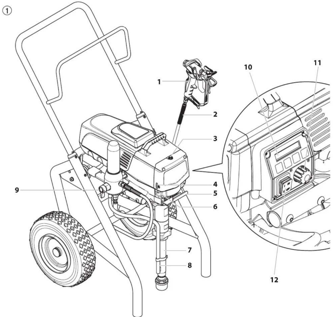
3.4 LEGEND FOR EXPLANATORY DIAGRAM PROSPRAY 3.31
- Spray gun
- High-pressure hose
- Oil cup for EasyGlide (EasyGlide prevents increased wear of the packings)
- Oil level gauge
- Pail hook
- Oil button
-
Suction tube
-
Return hose
- Relief valve
Lever position vertical – PRIME ( circulation) Lever position horizontal – SPRAY () - Digital Electronic Spray Control (DESC)
- Pressure control knob
- ON/OFF switch
3.5 EXPLANATORY DIAGRAM PS 3.31
3.6 TRANSPORTATION
Pushing or pulling the unit
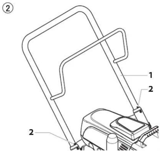
Pull out the handle (Fig. 2, Item 1) until it will come no further. Insert the handle – push the buttons (2) on the spars, and then push in the handle.
3.7 TRANSPORTATION IN VEHICLE
Secure the unit with a suitable fastening.
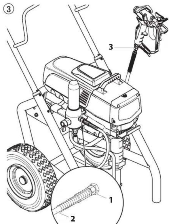
- Screw the high-pressure hose (2) to the coating material outlet (Fig. 3, Item 1).
- Screw the spray gun (3) with the selected tip onto the high-pressure hose.
- Tighten the union nuts at the high-pressure hoses firmly so that coating material does not leak.
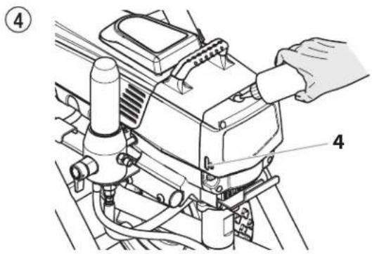
- Remove the oil cup cap with a straight-slot screwdriver.
- Fill the oil cup with EasyGlide (Fig. 4) until the oil gauge (4) is showing that it is full.

EasyGlide prevents increased wear and tear to the packings.
- Replace oil cup cap.
- Press oil button 2-5 times to prime the oiler. Press once for every eight hours of usage to lubricate the fluid section.
4.2 CONTROL PANEL INDICATORS
The following is a description of the control panel indicators.
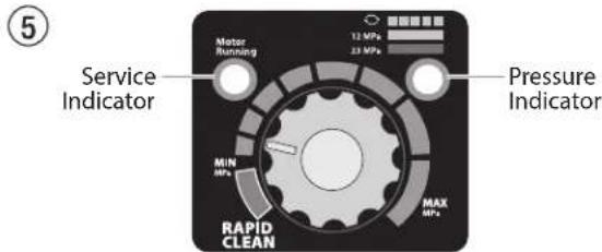
SERVICE INDICATOR
The Service indicator is on when the motor is commanded to run. This indicator is used by service centers to troubleshoot motor problems.
PRESSURE INDICATOR
The pressure indicator shows the current operating pressure of the sprayer. It has three different indications: blinking yellow, solid yellow, and solid green.
Blinking Yellow
When the pressure indicator is blinking yellow, the sprayer is operating between 0 and 1.4 MPa (14 bar). A blinking yellow pressure indicator means:
- The sprayer is plugged in and turned "ON"
• The sprayer is at priming pressure (little or no pressure) - It is safe to move the relief valve between positions
- It is safe to change or replace the spray tip
Solid Yellow
When the pressure indicator is solid yellow, the sprayer is operating between 1.4 MPa (14 bar) and 12 MPa (120 bar). A solid yellow pressure indicator means:
- The sprayer is at the proper pressure setting for spraying stain, lacquer, varnish, and multi-colors
Solid Green
When the pressure indicator is solid green, the sprayer is operating between 12 MPa (120 bar) and 23 MPa (230 bar). A solid green pressure indicator means:
- The sprayer is at the proper pressure setting for spraying oil-based and latex house paints
- The sprayer is operating at peak performance at a high pressure setting
- If the pressure indicator goes to solid yellow when the pressure is set so that it starts at solid green, it indicates one of the following:
a. Tip Wear Indicator — when spraying with latex or at high pressure the solid yellow appears. This means the tip is worn and needs to be replaced.
b. Tip Too Large — when a tip that is too large for the sprayer is put in the gun, the pressure indicator will turn from solid green to solid yellow.
c. Fluid Section Wear — if a solid yellow pressure indicator appears when using a new tip and the pressure is set at maximum, service may be required (worn packings, worn piston, stuck valve, etc...).
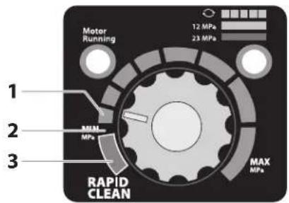
4.3 PRESSURE CONTROL KNOB SETTINGS

The pressure can be adjusted with the pressure regulator as well as with the SprayManager app. If the pressure has been changed while the pressure regulator is at the stop, the pressure regulator must first be moved to the centre so that the pressure can be set correctly with it again.
- Minimum pressure setting
- Black zone – no pressure generation
- Blue zone – pulsating pressure for cleaning
⑥
4.4 CONNECTION TO THE MAINS NETWORK

The unit must be connected to an appropriately-grounded safety outlet.
Before connecting the unit to the mains supply, ensure that the line voltage matches that specified on the unit's rating plate.
When connecting to the public low-voltage network, it is possible that approval of the network operator will be required. Check the regulations in force in your country and contact your network operator.
The connection must be equipped with a residual current protective device with INF ≤ 30 mA.

Wagner's accessories program also includes a mobile operator protection device for the electronic supply, which can also be used with other electronic equipment.
4.5 CLEANING PRESERVING AGENT WHEN STARTING-UP OF OPERATION INITIALLY
-
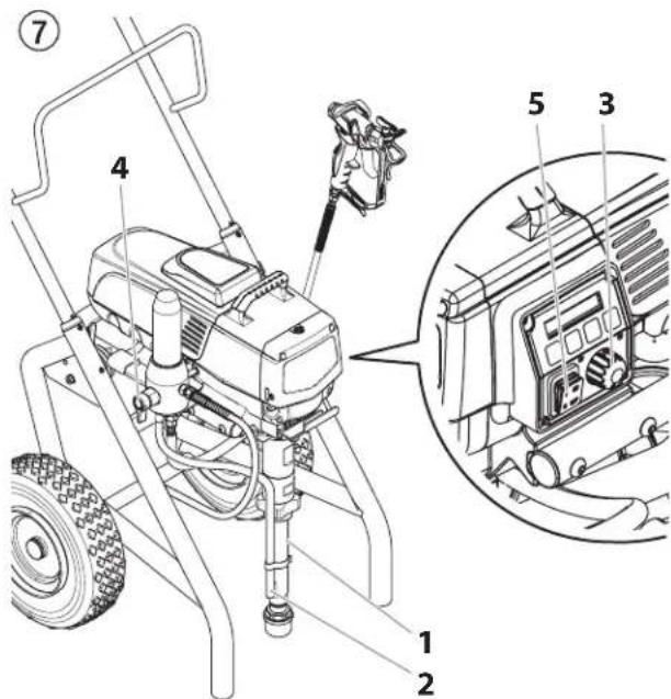
Immerse the suction tube (Fig. 7, Item 2) return hose (1) into a container with a suitable cleaning agent.
-
Turn the pressure control knob counterclockwise (3) to minimum pressure.
-
Open the relief valve (4), valve position PRIME (circulation).
-
Switch the unit (5) ON.
-
Wait until the cleaning agent exudes from the return hose.
-
Close the relief valve, valve position SPRAY (spray).
-
Pull the trigger of the spray gun.
-
Spray the cleaning agent from the unit into an open collecting container.
4.6 TAKING THE UNIT INTO OPERATION WITH COATING MATERIAL
- Immerse the suction tube (Fig. 7, Item 2) and return hose (1) into the coating material container.
- Turn the pressure control knob counterclockwise (3) to minimum pressure.
- Open the relief valve (4), valve position PRIME (circulation).
- Switch the unit (5) ON.
- Wait until the coating material exudes from the return hose.
- Close the relief valve, valve position SPRAY (spray).
- Trigger the spray gun several times and spray into a collecting container until the coating material exits the spray gun without interruption.
- Increase the pressure by slowly turning up the pressure control knob.
Check the spray pattern and increase the pressure until the atomization is correct.
Always turn the pressure control knob to the lowest setting with good atomization.
- The unit is ready to spray.
4.7 DIGITAL ELECTRONIC SPRAY CONTROL (DESC)

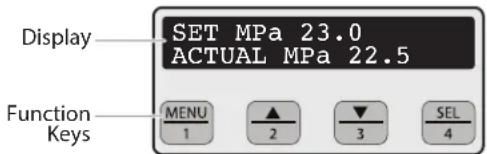
The Digital Electronic Spray Control (DESC) increases the functionality of the sprayer. It is installed directly below the pressure control knob on the control panel. It consists of a display and four function keys. The display shows various menu screens that allow the user to customize and monitor sprayer operation using the function keys.


The pressure control knob overrides the Digital Electronic Spray Control (DESC) settings. Anytime the pressure control knob is turned, the sprayer pressure will change accordingly.
FUNCTION KEYS
The function keys are numbered 1–4. Each key is labeled with an additional function as well.
| #1/Menu Key Pressing the #1 key scrolls through the available menu screens or performs a function described on the active menu screen. | |
| #2/▲Key | Pressing the #2 key performs a function described on the active menu screen or increases a value. |
| #3/▼Key | Pressing the #3 key performs a function described on the active menu screen or decrease a value. |
| #4/Select Key Pressing the #4 key selects the active menu screen or performs a function described on the active menu screen. | |
MENU SCREENS
Several menu screens are available for the user to customize and monitor sprayer operation. They include Main Screen, Volume Pumped, Job Volume, Unit Serial #, Timers, Job Timers, Service Time, Security Code, Prime, and Rapid Clean.
MAIN SCREEN
The Main Screen is the default screen for the control system at sprayer
| SET MPa | 23.0 |
| ACTUAL MPa | 22.5 |
startup. Pressing the #2 key switches between PSI, BAR and MPa units of
measure. Press the #1 key to scroll through the remaining menu screens.

For sprayers equipped with an nine-language Digital Electronic Spray Control (DESC):
Pressing the #2 key at the Main Screen switches between PSI, Bar and MPa units of measure.
Pressing the #3 key at the Main Screen changes the language of the text on the display. There are a total of nine languages available. Each time the #1 key is pressed, a different language will appear. The languages, in order of appearance, are: English, Spanish, Dutch, Danish, Swedish, German, French, Italian, and Portuguese.
VOLUME PUMPED SCREEN
The Volume Pumped screen shows the total number of gallons or liters sprayed by the sprayer.
To select the Volume Pumped screen, press the #4 key.
| VOLUME | PUMPED |
| MENU-1 | SELECT-4 |
| GALLONS | X |
| MENU-1 | LITRES-2 |
| LITRES | X |
| MENU-1 | GALLONS-2 |
JOB VOLUME SCREEN
The Job Volume screen allows the user to reset a liter counter to track usage on specific jobs.
To select the Job Volume screen, press the #4 key.
| JOB VOLUME | |
| MENU-1 | SELECT-4 |
| GALLONS | XXXX |
| MENU-1 | RESET-3 |
UNIT SERIAL # SCREEN
The Unit Serial # screen shows the sprayers serial number.
| UNIT | SERIAL # |
| MENU-1 | SELECT-4 |
To select the Unit Serial # screen, press the #4 key.
| SER # | XXXXXXXXXX |
| MENU-1 | |
TIMERS SCREEN
The Timers screen shows the total time the sprayer has been turned on as well as the total time the sprayer has been running (pumping).
| TIMERS | |
| MENU-1 | SELECT-4 |
To select the Timers screen, press the #4 key.
| ON TIME | XXXX |
| RUN TIME | XXXX |
JOB TIMERS SCREEN
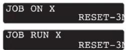
The Job Timers screen allows the user to reset the "ON TIME" and "RUN TIME" to track time on specific jobs.
To select the Job Timers screen, press the #4 key. "JOB ON" screen will appear. Press #3 to reset. Press #1 to continue to "JOB RUN" screen.
Press #3 to reset. Press #1 to scroll through the remaining menu screens.

SERVICE TIME SCREEN
The Service Time screen allows the user to set a service time interval (in hours). Below the set time, the
screens shows the current amount of hours on the sprayer since the last activation of the service timer. To select the Service Timer screen, press the #4 key.
To set the service time, press the #2 (up) and/or the #3 (down) keys to the desired time (run hours will increase/
decrease in increments of 25 for each time you press a key).
When the sprayer reaches the SERVICE@ time selected, the screen will display "SERVICE DUE". To reset the timer, press the #3 key when the pump is first turned on. This will reset the "SERVICE DUE" message and also reset the "SERVICE TIME" to the previous setting.


SECURITY CODE SCREEN
The Security Code screen allows the user to set a four digit security code to prevent unauthorized use of the
sprayer. If a security code has been set, the control system display will ask for the code at startup. If the correct code is entered, the display will show the Main Screen and the sprayer will operate. If the wrong code is entered, the display will continue to ask for the correct code and the sprayer will not work. To set or change the security code, press the #2 key.


If the sprayer is new, no security code is set and the Main Screen will appear at startup. When setting a security code for the first time, the "Enter Old Code Number" screen will appear, and you will need to enter "1111".
Enter the old security code number to access the screen that allows the code change. If the wrong code is entered, the display will continue to ask for the correct code and the security code cannot be changed.
Enter the new security code. Once the new code is entered, the display will automatically ask that the new code be re-entered for verification. If the same new code is re-entered, the display will confirm that the new
ENTER NEW CODE NUMBER XXXX
RE-ENTER NEW NUMBER XXXX
NEW CODE NUMBER ACCEPTED
code has been accepted and return to the Main Screen. If the new code is re-entered incorrectly, the display will return to the "Enter New Code Number" screen and the process will repeat.
If you forget or misplace your security code, you can contact Wagner customer service for assistance.

To inactivate the security function, enter "1111" at the "Enter New Code Number" screen (this is the default code that leaves the sprayer unlocked). As a result, the Main Screen will appear at sprayer startup.
PRIME SCREEN
The Prime screen appears when the pressure control knob is set at the "MIN" setting.
PRIME
RAPID CLEAN SCREEN
The Rapid Clean screen appears when the pressure control knob is
set at the RAPID CLEAN position and
the PRIME/SPRAY valve is in the PRIME position.

If there is no action at any menu screen for 30 seconds, the display will go back to the Main Screen.
5 SPRAYING

Injection hazard. Do not spray without the tip guard in place. NEVER trigger the gun unless the tip is completely turned to either the spray or the unclog position. ALWAYS engage the gun trigger lock before removing, replacing or cleaning tip.
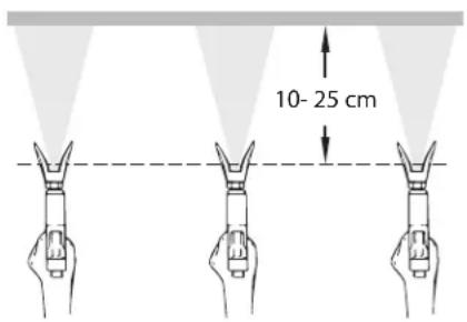
A) The key to a good paint job is an even coating over the entire surface. Keep your arm moving at a constant speed and keep the spray gun at a constant distance from the surface. The best spraying distance is 10 to 25 cm between the spray tip and the surface.
A
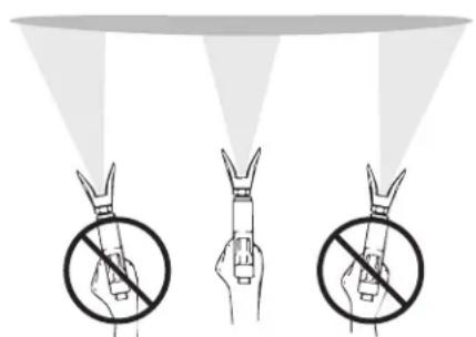
B) Keep the spray gun at right angles to the surface. This means moving your entire arm back and forth rather than just flexing your wrist.
Keep the spray gun perpendicular to the surface, otherwise one end of the pattern will be thicker than the other.
B
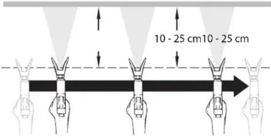
C) Trigger gun after starting the stroke. Release the trigger before ending the stroke. The spray gun should be moving when the trigger is pulled and released. Overlap each stroke by about 30%. This will ensure an even coating.
C

If very sharp edges result or if there are streaks in the spray jet – increase the operating pressure or dilute the coating material.
6 HANDLING THE HIGH-PRESSURE HOSE
| The unit is equipped with a high-pressure hose specially suited for piston pumps. | |
 | Danger of injury through leaking high-pressure hose. Replace any damaged high-pressure hose immediately.Never repair defective high-pressure hoses yourself! |
The high-pressure hose is to be handled with care. Avoid sharp bends and folds: the smallest bending radius is about 8" (20 cm).
Do not drive over the high-pressure hose. Protect against sharp objects and edges.
Never pull on the high-pressure hose to move the device.
Make sure that the high-pressure hose cannot twist. This can be avoided by using a Wagner spray gun with a swivel joint and a hose system.
 | When using the high-pressure hose while working on scaffolding, it is best to always guide the hose along the outside of the scaffolding. |
 | The risk of damage rises with the age of the high-pressure hose. Wagner recommends replacing high-pressure hoses after 6 years. |
 | Use only Wagner original-high-pressure hoses in order to ensure functionality, safety and durability. |
7 INTERRUPTION OF WORK
- Open the relief valve, valve position PRIME ( circulation).
- Switch the unit OFF.
- Turn the pressure control knob counterclockwise to minimum pressure.
- Pull the trigger of the spray gun in order to release the pressure from the high-pressure hose and spray gun.
- Secure the spray gun, refer to the operating manual of the spray gun.
- If a standard tip is to be cleaned, see Section 12.2.
If a non-standard tip is installed, proceed according to the relevant operating manual.
- Depending on the model, leave the suction tube or the suction hose and return hose immersed in the coating material or swivel or immerse it into a corresponding cleaning agent.
| Attention | If fast-drying or two-component coating material is used, ensure that the unit is rinsed with a suitable cleaning agent within the processing time. |
8 CLEANING THE UNIT (SHUTTING DOWN)
| A clean state is the best method of ensuring operation without problems. After you have finished spraying, clean the unit. Under no circumstances may any remaining coating material dry and harden in the unit. | |
| The cleaning agent used for cleaning (only with an ignition point above 21 °C) must be suitable for the coating material used. | |
| ·Secure the spray gun, refer to the operating manual of the spray gun.·Clean and remove tip.·For a standard tip, refer to Section 12.2.·If a non-standard tip is installed, proceed according to the relevant operating manual. |
- Remove suction hose from the coating material.
- Close the relief valve, valve position SPRAY (spray).
- Switch the unit ON.
 | The container must be earthed in case of coating materials which contain solvents. |
 | Caution! Do not pump or spray into a container with a small opening (bunghole)! |
- Pull the trigger of the spray gun in order to pump the remaining coating material from the suction hose, high-pressure hose and the spray gun into an open container.
- Immerse suction hose with return hose into a container with a suitable cleaning agent.
- Turn the pressure control knob counterclockwise to minimum pressure.
- Open the relief valve, valve position PRIME (circulation).
- Pump a suitable cleaning agent in the circuit for a few minutes.
- Close the relief valve, valve position SPRAY (spray).
- Pull the trigger of the spray gun.
- Pump the remaining cleaning agent into an open container until the unit is empty.
- Switch the unit OFF.
8.1 CLEANING UNIT FROM OUTSIDE
 | First of all pull out mains plug from socket. |
 Attention Attention | Danger of short circuit through penetrating water!Never spray down the unit with high-pressure or high-pressure steam cleaners.Do not put the high-pressure hose into solvents.Use only a wet cloth to wipe down the outside of the hose. |
Wipe down unit externally with a cloth which has been immersed in a suitable cleaning agent.
8.2 SUCTION FILTER

A clean suction filter always guarantees maximum feed quantity, constant spraying pressure and problem-free functioning of the unit.
-
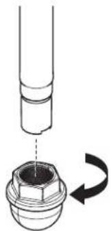
Screw off the filter (Fig. 8) from suction tube.
-
Clean or replace the filter.
Carry out cleaning with a hard brush and an appropriate cleaning agent.
⑧
natural_image
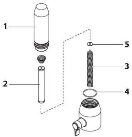
Diagram of a mechanical component with a rotating arrow indicating rotation (no text or symbols)8.3 CLEANING THE HIGH-PRESSURE FILTER

Clean the filter cartridge regularly. A soiled or clogged high-pressure filter can cause a poor spray pattern or a clogged tip.
- Turn the pressure control knob counterclockwise to minimum pressure.
- Open the relief valve, valve position PRIME (circulation).
- Switch the unit OFF.

Unplug the power plug from the outlet.
- Unscrew the filter housing (Fig. 9, Item 1). with a strap wrench.
- Pull the filter cartridge (2) from the bearing spring (3).
- Clean all the parts with the corresponding cleaning agent. If necessary, replace the filter cartridge.
- Check the O-ring (4), replace it if necessary.
- Place the bearing ring (5) against the bearing spring (3). Slide the filter cartridge (2) over the bearing spring.
- Screw in filter housing (1) and tighten it as far as possible with the strap wrench.
⑨
8.4 CLEANING AIRLESS SPRAY GUN

Clean the spray gun after each use.
- Rinse airless spray gun with an appropriate cleaning agent.
- Clean tip thoroughly with appropriate cleaning agent so that no coating material residue remains.
- Thoroughly clean the outside of the airless spray gun.
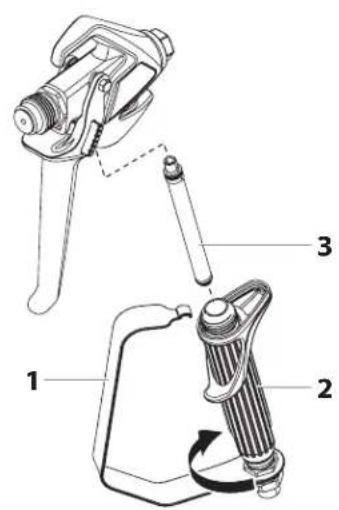
INTAKE FILTER IN AIRLESS SPRAY GUN (FIG. 10)
- Unclip the top of the trigger guard (1) from the gun head.
- Using the bottom of the trigger guard as a wrench, loosen and remove the handle assembly (2) from the gun head.
- Pull the old filter (3) out of the gun head. Clean or replace.
- Slide the new filter, tapered end first, into the gun head.
- Thread the handle assembly into the gun head. Tighten with the trigger wrench.
- Snap the trigger guard back onto the gun head.
10
9 REMEDY IN CASE OF FAULTS
| Type of malfunction | Possible cause | Measures for eliminating the malfunction |
| A. Unit does not start | 1. No voltage applied.2. Pressure setting too low.3. ON/OFF switch defective. | 1. Check voltage supply.2. Turn up pressure control knob.3. Replace. |
| B. Unit does not draw in material | 1. Relief valve is set to SPRAY (spray).2. Filter projects over the fluid level and sucks air.3. Filter clogged.4. Suction hose/suction tube is loose, i.e.the unit is sucking in outside air. | 1. Set relief valve to PRIME (circulation).2. Refill the coating material.3. Clean or replace the filter.4. Clean connecting points. Replace O-rings if necessary.Secure suction hose with retaining clip. |
| C. Unit draws in material, but the pressure does not build up | 1. Tip heavily worn.2. Tip too large.3. Pressure setting too low.4. Filter clogged.5. Coating material flows through the return hose when the relief valve is in the SPRAY (spray) position.6. Packings sticky or worn.7. Valve balls worn.8. Valve seats worn. | 1. Replace2. Replace tip.3. Turn pressure control knob clockwise to increase.4. Clean or replace the filter.5. Remove and clean or replace relief valve.6. Remove and clean or replace packings.7. Remove and replace valve balls.8. Remove and replace valve seats. |
| D. Coating material exits at the top of the fluid section | 1. Upper packing is worn.2. Piston is worn. | 1. Remove and replace packing.2. Remove and replace piston. |
| E. Increased pulsation at the spray gun | 1. Incorrect high-pressure hose type.2. Tip worn or too large.3. Pressure too high. | 1. Only use WAGNER original-high-pressure hoses in order to ensure functionality, safety and durability.2. Replace tip.3. Turn pressure control knob to a lower number. |
| F. Poor spray pattern | 1. Tip is too large for the coating material which is to be sprayed.2. Pressure setting incorrect.3. Volume too low.4. Coating material viscosity too high. | 1. Replace tip.2. Turn pressure control knob until a satisfactory spraying pattern is achieved.3. Clean or replace all filters.4. Thin out according to the manufacturer's instructions. |
| G. Unit loses power | 1. Pressure setting too low. | 1. Turn pressure control knob clockwise to increase. |
| H. Pump over-pressurizes and will not shut off. | 1. Pressure switch defective.2. Transducer defective. | 1. Take unit to a Wagner authorized service center.2. Take unit to a Wagner authorized service center. |
10 SERVICING
10.1 GENERAL SERVICING
Servicing of the unit should be carried out once annually by the WAGNER service.
- Check high-pressure hoses, device connecting line and plug for damage.
- Check the inlet valve, outlet valve and filter for wear.
10.2 HIGH-PRESSURE HOSE
Inspect the high-pressure hose visually for any notches or bulges, in particular at the transition in the fittings. It must be possible to turn the union nuts freely.

The risk of damage rises with the age of the high-pressure hose. Wagner recommends replacing high-pressure hoses after 6 years.
11 REPAIRS AT THE UNIT
 | Switch the unit OFF.Before all repair work: Unplug the power plug from the outlet. |
 | Make sure to check for grounding continuity after service is performed on any electrical components.Use an ohmmeter to determine that there is continuity between accessible dead-metal parts of the product and the grounding blade of the attachment plug. |
11.1 INLET AND OUTLET VALVE
- Remove the four screws in the front cover and then remove the front cover.

Danger of crushing - do not reach with the fingers or tool between the moving parts.
- Turn the pressure control knob to minimum pressure. The DESC screen should say "PRIME".
- Press the #1 key on the DESC control panel. The "CREEP MODE" screen will now appear.
-
Slowly turn the pressure control knob clockwise to increase the pressure. The crankshaft/slider assembly will begin to move very slowly.
-
When it reaches the bottom, dead-center of its stroke, turn the pressure control knob back to minimum pressure. The crankshaft/slider assembly should stop.
- Unplug the power plug from the outlet.
- Pull off clamp on suction tube and remove return hose.
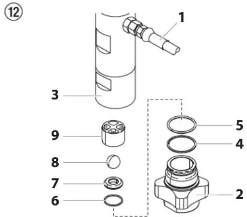
- Unscrew the connection hose (Fig. 12, item 1) from the high-pressure filter.
- Turn the knob on the side of the cart clockwise to unlock the cart. Tilt the cart backwards until it locks into place.
- Loosen and unscrew inlet valve housing (2) from the lower housing (3) with light blows from a hammer or unscrew with an adjusting wrench.
- Remove bearing ring (4), O-ring (5), O-ring (6), inlet valve seat (7), inlet valve ball (8) and upper ball guide (9).
- Clean all the parts with the corresponding cleaning agent.
Check the inlet valve housing (2), inlet valve seat (7) and inlet valve ball (8) for wear and replace the parts if necessary. If the worn inlet valve seat (7) is unused on one side, install it the other way around.
- Carry out installation in the reverse order.
Lubricate O-ring (5) with machine grease and ensure proper seating in the inlet valve housing (2).
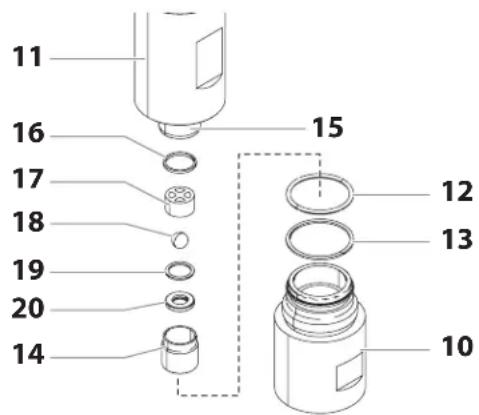
- Unscrew lower housing (Fig. 13, Item 10) with adjusting wrench while holding the upper housing (11) securely with a second adjusting wrench.
- Remove bearing ring (13) and O-ring (12).
- Screw out outlet valve housing (14) from the piston (15) with 3/8 inch hexagon socket head wrench.
- Remove the upper seal (16), upper ball guide (17), outlet valve ball (18), washer (19) and outlet valve seating (20).
- Clean all the parts with the corresponding cleaning agent. Check outlet valve housing (14), outlet valve seat (20), outlet valve ball (18) and upper ball guide (17) for wear and replace parts if necessary. If the worn outlet valve seat (20) is unused on one side, install it the other way around.
PS 3.1
- Carry out installation in the reverse order.
Lubricate O-ring (12) with machine grease and ensure proper seating in the lower housing (10).
13
11.2 DIGITAL ELECTRONIC SPRAY CONTROL (DESC) ERROR MESSAGES
The following error message screens appear whenever the Digital Electronic Spray Control (DESC) detects a problem with the sprayer. Once a problem occurs and the error message appears, the sprayer will shut down.

Before proceeding, relieve any pressure remaining in the system (valve position PRIME G). Additionally, follow all other warnings to reduce the risk of an injection injury, injury from moving parts or electric shock. Always unplug the sprayer before servicing!
CHECK TRANSDUCER SCREEN
The Check Transducer screen appears
when the transducer has become
disconnected or is defective. Take the sprayer to a Wagner
authorized service center for repair.
CHECK
TRANSDUCER
CHECK POTENTIOMETER SCREEN
The Check Potentiometer screen
appears when the potentiometer has
become disconnected or is defective. Take the sprayer to a
Wagner authorized service center for repair.
CHECK
POTENTIOMETER
CHECK MOTOR SCREEN
Indicates the motor is shut down due
to connection problems between
the motor and controller. Take the sprayer to a Wagner
authorized service center for repair.
CHECK
MOTOR
LOW VOLTAGE SCREEN
The Low Voltage screen appears when
the sprayer shuts down because of
low input voltage. Check the power supply and correct the problem. Restart the sprayer.
LOW
VOLTAGE
The High Motor Temperature screen
appears when the temperature of
the motor has risen too high. Take the sprayer to a Wagner
authorized service center for repair.
HIGH MOTOR
TEMPERATURE
HIGH MECHANICAL LOAD
The High Mechanical Load screen
appears when the sprayer shuts down
because of high current or when the sprayer goes into current fold back mode. Take the sprayer to a Wagner authorized
service center for repair.
HIGH MECHANICAL
LOAD
Indicates the DESC is shut down due to
excessive heat. Take the sprayer to a
Wagner authorized service center for repair.
HIGH CONTROL
TEMPERATURE
BAD HALL CYCLE POWER SCREEN
Indicates the motor or motor hall
affect sensors are defective. Take the
sprayer to a Wagner authorized service center for repair.
BAD HALL CYCLE
POWER
12 APPENDIX
12.1 SELECTION OF TIP
To achieve faultless and rational working, the selection of the tip is of the greatest importance.
In many cases the correct tip can only be determined by means of a spraying test.
SOME RULES FOR THIS:
The spray jet must be even.
If streaks appear in the spray jet the spraying pressure is either too low or the viscosity of the coating material to high.
REMEDY: Increase pressure or dilute coating material. Each pump conveys a certain quantity in proportion to the size of the tip:
The following principle is valid: large tip = low pressure small tip = high pressure
There is a large range of tips with various spraying angles.
12.2 SERVICING AND CLEANING OF AIRLESS HARD-METAL TIPS
STANDARD TIPS
If a different tip type has been fitted, then clean it according to manufacturer's instructions.
The tip has a bore processed with the greatest precision. Careful handling is necessary to achieve long durability. Do not forget the fact that the hard-metal insert is brittle! Never throw the tip or handle with sharp metal objects.
The following points must be observed to keep the tip clean and ready for use:
- Turn the relief valve handle fully counterclockwise (Circulation).
- Remove the tip from the spray gun.
- Place tip in an appropriate cleaning agent until all coating material residue is dissolved.
- If there is high-pressure air available, blow out tip.
- Remove any residue by means of a sharp wooden rod (toothpick).
- Check the tip with the help of a magnifying glass and, if necessary, repeat points 3 to 5.
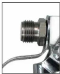
12.3 SPRAY GUN ACCESSORIES
| Adapter Order no. | |
| F to G-thread 2389689 | |
| G to F-thread 2405153 |
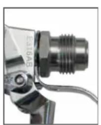
natural_image
Close-up of a mechanical component with threaded end and metallic body (no visible text or symbols)G-thread (7/8")
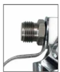
natural_image
Close-up of a metallic mechanical component with threaded end and coiled cable (no visible text or symbols)F-thread (11/16")
Tip extension with slewable knee joint (without tip)
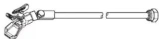
Length: 0.9 m Order no. 2418862
Length: 1.8 m Order no. 2418863
Tip extension

12.5 cm, G-thread, Order no. 2418853
25 cm, G-thread, Order no. 2418854
50 cm, G-thread, Order no. 2418855
75 cm, G-thread, Order no. 2418856
HEA NOZZLES FOR LOW-MIST SPRAYING AT LOW PRESSURE
HEA
HIGH EFFICIENCY
AIRLESS
HEA stands for High Efficiency Airless, an innovative nozzle technology revolutionising airless spraying. HEA nozzles allow the pressure of the spray device to be reduced right down and allow it to work in the low-pressure range (ideally at 80 - 140 bar). The nozzles can be used with all TradeTip 3 nozzle holders and WAGNER devices.
Some paints may need to be diluted to achieve the best result possible. The experts at Wagner application technology have therefore tested a wide range of materials for you. Their recommendations can be found in the Wagner Spray Guide at sprayguide.wagner-group.com.
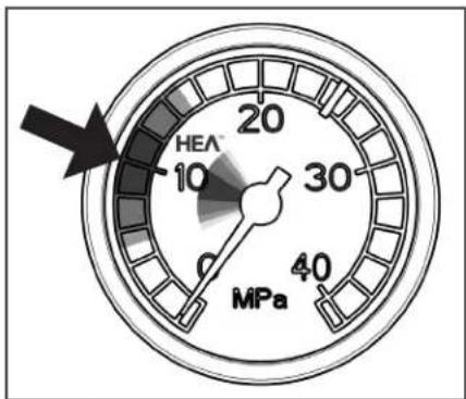
gauge
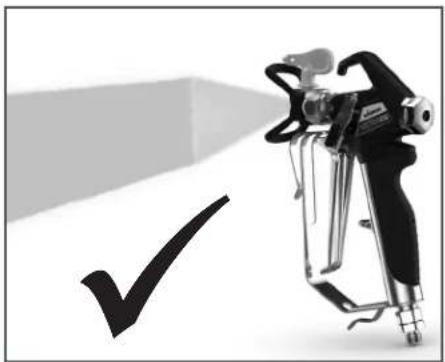
| Value | |-------| | 10 |Set the low pressure in the HEA range and start.
natural_image
Illustration of a spray gun with a checkmark symbol (no text or symbols present)Even spray pattern without spray edges.
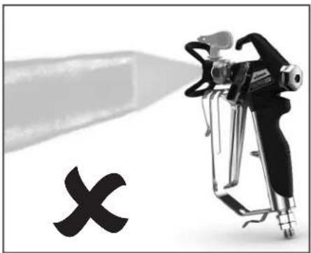
If edges are visible, slowly increase the pressure.
HEA tip table

All of the tips in the table below are supplied together with the appropriate gun fi iter.
| Application Tip marking Spray | angle | Bore inch / mm | Spraying width mm 1) | Gun fi Iter Order no. | ||
| Synthetic-resin paints | 211 | 20^ | 0.011 / 0.28 | 120 | red | 0554211 |
| PVC paints | 311 | 30^ | 0.011 / 0.28 | 150 | red | 0554311 |
| 411 | 40^ | 0.011 / 0.28 | 190 | Rot | 0554411 | |
| Paints, primers | 213 | 20^ | 0.013 / 0.33 | 120 | red | 0554213 |
| Fillers | 313 | 30^ | 0.013 / 0.33 | 150 | red | 0554313 |
| 413 | 40^ | 0.013 / 0.33 | 190 | red | 0554413 | |
| Fillers | 415 | 40^ | 0.015 / 0.38 | 190 | yellow | 0554415 |
| Rust protection paints | 515 | 50^ | 0.015 / 0.38 | 225 | yellow | 0554515 |
| 615 | 60^ | 0.015 / 0.38 | 270 | yellow | 0554615 | |
| Rust protection paints | 417 | 40^ | 0.017 / 0.43 | 190 | white | 0554417 |
| Latex paints | 517 | 50^ | 0.017 / 0.43 | 225 | white | 0554517 |
| Dispersions | 617 | 60^ | 0.017 / 0.43 | 270 | white | 0554617 |
| Rust protection paints | 519 | 50^ | 0.019 / 0.48 | 225 | white | 0554519 |
| Latex paints | 619 | 60^ | 0.019 / 0.48 | 270 | white | 0554619 |
| Dispersions | ||||||
| Flame retardant 421 | 40^ | 0.021 / 0.53 | 190 | white | 0554421 | |
| 521 | 50^ | 0.021 / 0.53 | 225 | white | 0554521 | |
| 621 | 60^ | 0.021 / 0.53 | 270 | white | 0554621 | |
1) Spray width at about 30 cm to the object and 100 bar (10 MPa) pressure with synthetic-resin paint 20 DIN seconds.
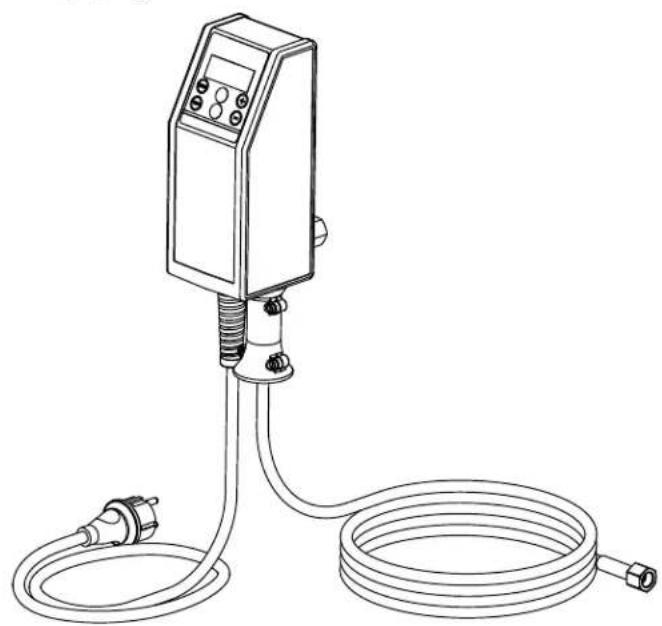
12.4 TEMPSPRAY
The paint material is heated to the required temperature uniformly by an electric heating element, which is located inside the hose (regulated from 20°C to 60°C).
Advantages:
- Constant paint temperature even at low outside temperatures
- Considerably better working of high viscosity coating materials
• Increased application efficiency
• Savings in solvents due to reduction in viscosity
• Adaptable to all airless units
| Order No. | Description |
| 23116592311852 | TempSpray H 126 (ideal for lacquer jobs)Basic unit 1/4" incl. stainless steel hose, DN6, 1/4", 10mSpraypack consisting of: basic unit (2311659), Airless gun Vector Grip G thread, incl. Trade Tip 3 nozzle holder and Trade Tip 3 FineFinish nozzle 410 |
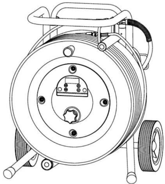
| 23116602311853 | TempSpray H 226 (ideal for dispersions/materials with high viscosity)Basic unit 1/4" incl. Hose reel, heated hose DN10, 15m, hose 1/4" DN4, 1mSpraypack consisting of: Basic unit (2311660), Airless un AG 14 G thread, incl. Trade Tip 3 nozzle holder and HEA nozzle 517 |
| 23116612311854 | TempSpray H 326 (ideal for dispersions/materials with high viscosity)Basic unit 1/4" incl. Hose reel, heated hose DN10, 30m, hose 1/4" DN4, 1mSpraypack consisting of: Basic unit (2311661), Airless un AG 14 G thread, incl. Trade Tip 3 nozzle holder and HEA nozzle 521 |
TempSpray H 126
natural_image
Line drawing of a handheld industrial control device with coiled tubing and connector (no text or symbols)TempSpray H 226 / H 326
natural_image
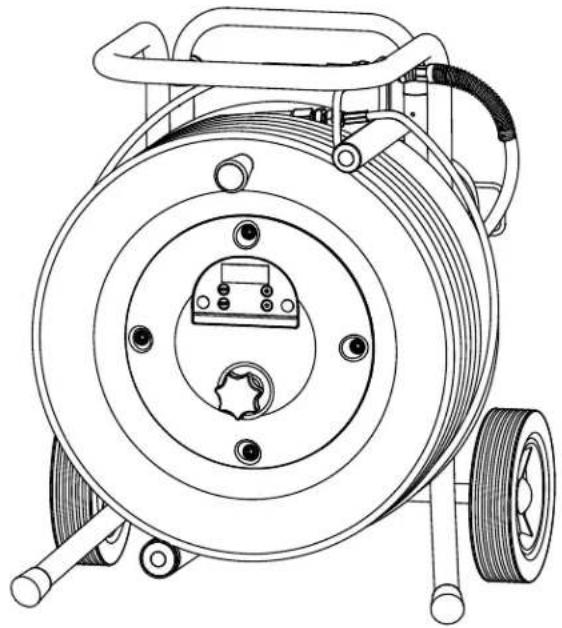
Technical line drawing of a mechanical power spool with coiled cable and mounting feet (no text or symbols)12.5 PUMP-RUNNER
(Order No. 2306987)
Universal accessories for cleaning, clean transportation and preservation of the pump unit.
Features:
- Simpler cleaning – the cleaning liquid circulates constantly through the pump making thorough cleaning of the interior
• No cleaning necessary during work stoppage or change of location because the paint in the pump cannot dry out or leak - Better protection
- Simple assembly
Suitable for the following models:
| Diaphragm Pumps Double-stroke piston pumps | |||
| SF 21 | Finish 270/370 | PS 24 | PS 3.25 |
| SF 23 | Nespray Deco | PS 26 | PS 3.29 |
| SF 27 | Nespray 31 | PS 30 | PS 3.31 |
| SF 31, SF 33 | Nespri Pro | PS 34 | PS 3.34 |
| SF 7000 | |||

Order this at the same time:
EasyClean, cleaning and preservation agent (1 l) Order no. 2412656.
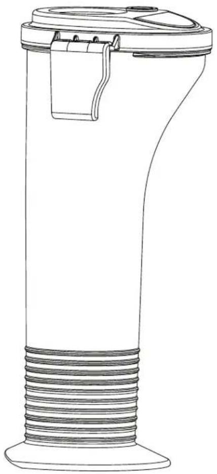
natural_image
Line drawing of a cylindrical mechanical component with threaded base and top clamped end (no text or symbols)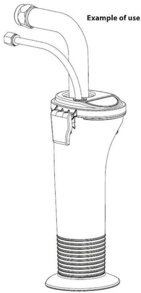
TESTING OF THE UNIT
For safety reasons, we would recommend having the device checked by an expert as required but at least every 12 months to ensure that it can continue to operate safely.
In the case of unused devices, the check can be postponed until they are next started up.
All (potentially deviating) national inspection and maintenance regulations must also be observed.
If you have any questions, please contact the customer service team at Wagner.
IMPORTANT INFORMATION ON PRODUCT LIABILITY
According to an EU directive, the manufacturer is only liable without limitation for faults in the product if all parts come from the manufacturer or have been approved by the manufacturer and have been mounted to the device and are operated properly. If third-party accessories or spare parts are used, the manufacturer is exonerated wholly or partly from his/her liability if use of the third-party accessories or spare parts have caused a defect in the product. In extreme cases, the relevant authorities can completely prohibit using the entire device.
With original WAGNER accessories and spare parts, compliance with all safety regulations is guaranteed.
NOTE ON DISPOSAL
In observance of the European Directive 2012/19/EU on waste electrical and electronic equipment and implementation in accordance with national law, this product is not to be disposed of together with household waste material but must be recycled in an environmentally friendly way!

Wagner or one of our dealers will take back your used Wagner waste electrical or electronic equipment and will dispose of it for you in an environmentally friendly way. Please ask your local Wagner service centre or dealer for details or contact us direct.
EU Declaration of conformity
We declare under sole responsibility that this product conforms to the following relevant stipulations:
2006/42/EC, 2014/30/EU, 2014/53/EU, 2011/65/EU, 2012/19/EU
Applied harmonised norms:
EN 62841-1, EN 1953, EN IEC 55014-1, EN IEC 55014-2,
EN IEC 61000-3-2, EN 61000-3-3, EN 62479, ETSI EN 301 489-1, ETSI EN 301 489-17, ETSI EN 300 328
The EU declaration of conformity is enclosed with the product. If required, it can be re-ordered using order number 2432213.
3 + 2 YEAR GUARANTEE ON THIS WAGNER CRAFTSMAN PRODUCT
(Status 03.03.2022)
WAGNER exclusively provides the commercial buyer who has purchased the product from an authorised specialist dealer (hereinafter referred to as the „Customer“) with a warranty for the products listed on the Internet at https://go.wagner-group.com/3plus2-info in addition to the statutory warranty regulations, unless there is a warranty exclusion.
The warranty period for WAGNER products (devices) in the craftsmen's sector is 36 months and begins with the date of purchase of the initial purchase. This warranty period is extended by a further 24 months if the product is registered within 28 days of purchase on the Internet at https://go.wagner-group.com/3plus2.
In cases of commercial rental, industrial use (e.g. use in shift operation) or equivalent use, the warranty period is 12 months due to the significantly higher load. We reserve the right to carry out a check in individual cases and refuse the warranty where necessary.
If any material, machining or performance defects are identified in the device within the warranty period, then the warranty claims must be made immediately and within a period of no more than 2 weeks following discovery of the defect.
The detailed guarantee conditions can be obtained on request from our authorised WAGNER partners (see website or operating instructions) or in text form on our website:
https://go.wagner-group.com/pf-warranty-conditions

Subject to modifications
UKCA Declaration of conformity
We declare under sole responsibility that this product conforms to the following relevant regulations:
Supply of Machinery (Safety) Regulations 2018
Electromagnetic Compatibility Regulations 2016
Radio Equipment Regulations 2017
The Restriction of the Use of Certain Hazardous Substances in Electrical and Electronic Equipment Regulations 2012
The Waste Electrical and Electronic Equipment Regulations 2013
Applied harmonised standards
BS EN 62841-1, BS EN 1953, BS EN IEC 55014-1, BS EN IEC
55014-2, BS EN 61000-3-2, BS EN 61000-3-3, BS EN 62479,
ETSI EN 301 489-1, ETSI EN 301 489-17, ETSI EN 300 328
1 CONSIGNES GÉNÉRALES DE SÉCURITÉ ____ 54
2 PRESCRIPTIONS DE SÉCURITÉ POUR LA PROJECTION AIRLESS 55
3 GÉNÉRALITÉS D'UTILISATION / DESCRIPTION DU MATÉRIEL 58
https://go.wagner-group.com/technology
3.2 PRODUITS DE REVÊTEMENT
PRODUITS UTILISABLES

3.6 TRANSPORT
3.7 TRANSPORT PAR VÉHICULE
4.2 VOYANTS DU PANNEAU DE COMMANDES
4.6 MISE EN SERVICE DU MATÉRIEL AVEC LE PRODUIT DE REVÊTEMENT
m = 311
TPS EXE
REINI-31
REINI-3
SERVICE TIME SCREEN (FENÊTRE D'HEURES DE SERVICE)
natural_image
Mechanical assembly diagram showing a bolt being inserted into a cylindrical component with a curved arrow indicating rotation (no text or symbols)8.3 NETTOYAGE DU FILTRE HAUTE PRESSION

9 DÉPANNAGE
12.1 CHOIX DES BUSES
natural_image
Close-up of a metallic mechanical component with threaded end and attached cable (no visible text or symbols)Filetage G (7/8")
natural_image
Close-up of a mechanical component with threaded connector and curved pipe (no visible text or symbols)Filetage F (11/16")
natural_image
Illustration of a spray gun with a checkmark symbol (no text or symbols present)natural_image
Line drawing of a handheld industrial sensor or pressure controller with coiled tubing and connector (no text or symbols)TempSpray H 226 / H 326
natural_image
Technical line drawing of a mechanical pump or reel assembly with no visible text or symbols12.5 PUMP-RUNNER
(Réf. No. 2306987)
natural_image
Line drawing of a cylindrical mechanical component with threaded base and mounting bracket (no text or symbols)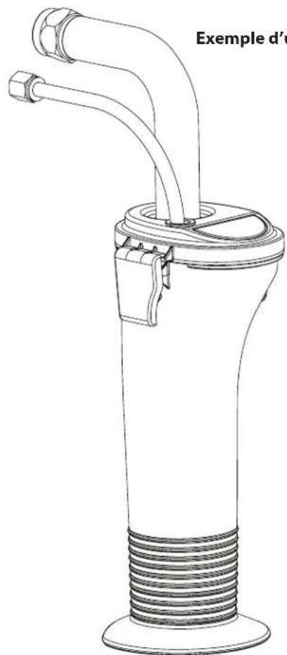
natural_image
Line drawing of a mechanical device with two pipes and a threaded base (no text or symbols)CONTRÔLE DE L'APPAREIL
INDICATION DE MISE AU REBUT
https://go.wagner-group.com/pf-warranty-conditions

https://go.wagner-group.com/technology
3.2 MATERIALI DI COPERTURA
MATERIALI DI COPERTURA LAVORABILI

3.6 TRASPORTO
3.7 TRASPORTO CON UN VEICOLO
4.2 INDICATORI DEL PANNELLO DI CONTROLLO
4.6 MESSA IN SERVIZIO DELL'APPARECCHIO CON MATERIALE DI COPERTURA
| # SER. | XXXXXXXXXX |
| MENU-1 |
VIDEATA TIMERS (TEMPORIZZATORI)
natural_image
Mechanical assembly diagram showing a bolt and nut assembly with rotation arrow (no text or symbols)8.3 PULIZIA DEL FILTRO AD ALTA PRESSIONE
La videata Check Transducer compare
natural_image
Close-up of a metallic mechanical component with threaded end and attached cable (no visible text or symbols)natural_image
Close-up of a mechanical component with threaded connector and metallic housing (no visible text or symbols)Filettatura F (11/16")
natural_image
Illustration of a spray gun with a checkmark symbol (no text or labels)natural_image
Line drawing of a handheld industrial control device with coiled tubing and connector (no text or symbols)TempSpray H 226 / H 326
natural_image
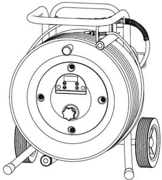
Technical line drawing of a mechanical pump or reel assembly with no visible text or symbols12.5 PUMP-RUNNER
(N° ord. 2306987)
natural_image
Line drawing of a cylindrical mechanical component with threaded base and central clip (no text or symbols)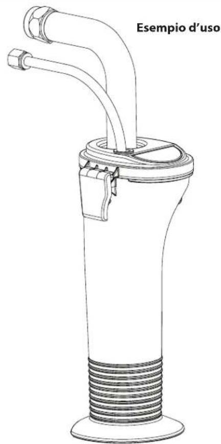
https://go.wagner-group.com/pf-warranty-conditions

You can find further accessories for optimised working at https://go.wagner-group.com/accessories-professional
| # PS | 3.31 Benennung | Description Désignation Denominazione | |||
| 1 805-254A Front | abdeckung /Baugruppe Öler | Face plate / oilerassembly | Ensemble graisseur /plaque frontale | Gruppo disco portapezzo /oliatore | |
| 2 700-139 Schraube (4) Screw (4) Vis (4) Vite (4) | |||||
| 3 805-467 Eimerhaken Pail hook Crochet de seau Gancio di secchio | |||||
| 4 | 9821 503 | Scheibe (2) | Washer (2) | Rondelle (2) | Rondella (2) |
| 5 805-625 Schraube (2) Screw (2) Vis (2) Vite (2) | |||||
| 6 | 800-904 | Rücklaufschlauch | Return tube | Tuyau de retour | Tubo flessibile di ritorno |
| 7 | 0507 387 | Schlauch | Hose | Tuyau | Flessibile |
| 8 | ----* | Abstandhalter | Spacer | Entretoise | Distanziatore |
| 9 | ----* | Obere Packung | Upper | Garniture supérieure | Guarnizione superiore |
| 10 | ----* | Untere Packung | Lower packing | Garniture inférieure | Guarnizione inferiore |
| 11 | ----* | Führungsring | Guide ring | Bague de guidage | Anello di guida |
| 12 | ----* | O-ring (2) | O-ring (2) | Joint torique (2) | O-ring (2) |
| 13 | ----* | O-ring (2) | O-ring (2) | Joint torique (2) | O-ring (2) |
| 14 | ----* | Obere Dichtung | Upper seal | Joint supérieur | Guarnizione superiore |
| 15 | ----* | Auslassventilkugel | Outlet valve ball | Bille du clapet derefoulement | Sfera della valvola discarico |
| 16 | ----* | Scheibe | Washer | Rondelle | Rondella |
| 17 | ----* | Einlassventilkugel | Inlet valve ball | Bille du clapet d'admission | Sfera della valvola dientrata |
| 18 | ----* | O-ring | O-ring | Joint torique | O-ring |
| 19 | 730-334 | Klammer | Clip | Agrafe de fixation | Fermaglio |
| 20 | 451-241 | Ansaugrohr | Suction tube | Tube d'aspiration | Tubo di aspirazione |
| 21 | 5006 536 | Filter | Inlet screen | Filtre | Filtro |
| 0508 221 | Repacking Kit -1 (inklusive derElemente 8-18). | Repacking kit - 1(includes items 8-18) | Kit de remplacement desgarnitures - 1 (comprendles éléments 8 à 18). | Kit di riconfezionamento- 1 (comprende articoli8-18). | |
| 0558 729 | Repacking Kit -2 (inklusive derElemente 8-10). | Repacking kit - 2(includes items 8-10). | Kit de remplacement desgarnitures - 2 (comprendles éléments 8 à 10). | Kit di riconfezionamento- 2 (comprende articoli8-10). | |
* Nur als Teil eines Service Sets erhältlich. / Only available as part of a service set. / Disponible exclusivement dans l'un des kits de réparation. / Disponibile soltanto come parte di un kit di assistenza.
DE HOCHDRUKFILTER EN FILTER ASSEMBLY
FR FILTER HAUTE PRESSION IT FILTRO AD ALTA PRESSIONE
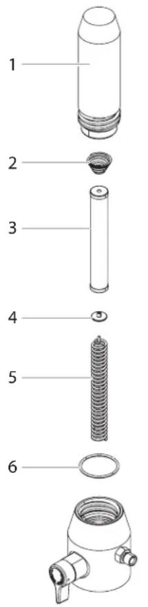
| # | PS 3.31 Berennung Description Désignation Denominazione | ||||
| 1 | 800-705 | Filtergehäuse | Filter housing | Corps de filtre | Scatola del filtro |
| 2 | 14058 | Konusfeder | Conical spring | Ressort | Molla conica |
| 3 730-067 Filterpatrone, 60 Maschen(Standardausrüstung) | Filter, 60 mesh (standard) | Filtre, 60 mailles (standard) | Filtro, 60 maglie (standard) | ||
| 4 702-251 Stützscheibe Bearing ring | Rondelle | Rondella | |||
| 5 | 757-105 | Stützfeder | Bearing spring | Ressort | Molla di spinta |
| 6 | 800-906 | O-ring | O-ring | Joint torique | O-ring |
DE WAGEN EN CART ASSEMBLY
FR CHARIOT IT CARELLO
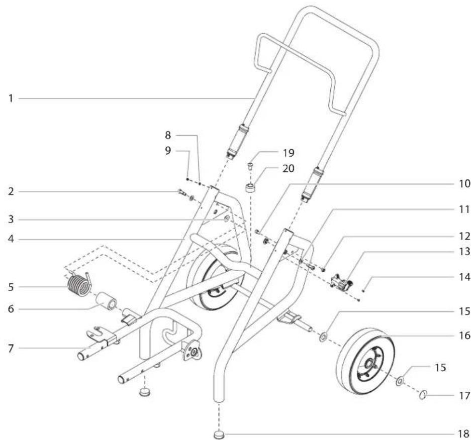
| # | PS 3.31 Berennung | Description Désignation | Denominazione | ||
| 1 805-279A Handgriff | inklusive der Elemente 8-9) | Handle assembly (includes items 8-9) | Poignée (comprend les éléments 8-9) | Impugnatura (comprende articoli n 8-9) | |
| 2 9805352 Schraube (2) | Screw (2) Vis (2) Vite (2) | ||||
| 3 805-451 Buchse Bushing Bague Boccola | |||||
| 4 | 805-202 | Grundgestell | Cart weldment | Châssis de base | Telaio di base |
| 5 | 9894 275 | Stützfeder | Spring | Ressort | Molla |
| 6 805-589 Buchse Sleeve | Douille | Bussola | |||
| 7 | 0290 244 | Baugruppe Wagen | Carriage assembly | Ensemble chariot | Gruppo di trasporto |
| 8 | 856-002 | Scheibe (4) | Washer (4) | Rondelle (4) | Rondella (4) |
| 9 856-921 Schraube (4) | Screw (4) Vis (4) Vite (4) | ||||
| 10 | 0279 481 | Schraube | Screw | Vis | Vite |
| 11 | 9820 305 | Scheibe (2) | Washer (2) | Rondelle (2) | Rondella (2) |
| 12 | 756-114 | Arretiermutter | Jam nut | Ecrou d'arrêt | Dado di arresto |
| 13 | 805-228A | Baugruppe Nocken | Cam assembly | Ensemble came | Gruppo camma |
| 14 | 9805 353 | Schraube (2) Screw (2) Vis (2) | Vite (2) | ||
| 15 | 0294 534 | Abstandhalter (4) | Spacer (4) | Entretoise (4) | Distanziatore (4) |
| 16 | 0278 373 | Rad (2) | Wheel (2) | Roue (2) | Ruota (2) |
| 17 | 9890 104 | Radkappe (2) | Axle cap (2) | Chapeau de roue (2) | Coppa coprimozzo (2) |
| 18 | 9885 571 | Verschlussstopfen (2) | Plug (2) | Bouchon (2) | Tappo (2) |
| 19 | 54458 | Schraube (2) Screw (2) Vis (2) | Vite (2) | ||
| 20 | 13538 | Fuß (2) | Pad (2) | Pied (2) | Piede (2) |
A J. Wagner Ges.m.b.H.
Ottogasse 2/20
2333 Leopoldsdorf
Österreich
Tel. +43/2235/44158
Telefax +43/ 2235 / 44 163
offi ce@wagner-group.at
DK DVA A/S
Marielundvej 48 C
2730 Herlev
Denmark
Tel. +45 70 234 239
info@dva.dk
www.dva.dk
I Wagner S.p.A.
23868 Valmadrera (Lc)
Via Santa Vecchia, 109
Italia
Tel./Fax 0341 210100 (centralino)
wagner_it_va@wagner-group.com
B WSB Finishing Equipment
Veilinglaan 56-58
1861 Meise-Wolvertem
Belgium
Tel. +32/2/269 46 75
Telefax +32/2/269 78 45
info@wagner-wsb.nl
NL WSB Finishing Equipment BV
De Heldinnenlaan 200,
3543 MB Utrecht
Netherlands
Tel. +31/ 30/241 41 55
Telefax +31/ 30/241 17 87
info@wagner-wsb.nl
CH Wagner International AG
Industriestrasse 22
9450 Altstätten
Schweiz
Tel. +41/71 / 7 57 22 11
Telefax +41/71 / 7 57 22 22
wagner@wagner-group.ch
F J.Wagner France Sarl
Parc Work Center
S Orkla House Care AB,
Tallvägen 6
564 23 Bankeryd,
Sweden
Tel. +46 36 376300
Info@orkla.se
D J. Wagner GmbH
Wagner Spraytech (UK) Limited
Innovation Centre
Silverstone Park, Silverstone
Northants NN12 8GX
Great Britain
Tel. 01327 368410
enquiries@wagnerspraytech.co.uk
AUS Wagner Spraytech Australia Pty. Ltd.
8 - 10 Dansu Court
Hallam, Victoria, 3803
Australia
Customer Service 1800 924 637
info@wagneraustralia.com.au
RU Импортёр:
ООО «ВинТех рус»

- PROSPRAY 3.31 CONNECT
- DE WAGNER SprayManager App\*
- FR App WAGNER SprayManager\*
- EXPLOSIONSSCHUTZ
- TRANSPORT
- TRANSPORT IM FAHRZEUG
- HOCHDRUCKFILTER REINIGEN
- REPARATUREN AM GERÄT
- PUMP-RUNNER
- (Best. Nr. 2306987)
- PRÜFUNG DES GERÄTES
- Translation of the original operating manual
- GENERAL SAFETY INSTRUCTIONS 29
- SAFETY REGULATIONS FOR AIRLESS SPRAYING 30
- GENERAL VIEW OF APPLICATION 33
- SPRAYING TECHNIQUE 41
- HANDLING THE HIGH-PRESSURE HOSE \_\_\_\_ 41
- INTERRUPTION OF WORK 42
- CLEANING THE UNIT (SHUTTING DOWN) \_ 42
- REMEDY IN CASE OF FAULTS 45
- SERVICING 46
- REPAIRS AT THE UNIT 46
- APPENDIX 48
- IMPORTANT NOTES ON PRODUCT LIABILITY \_\_\_\_ 52
- 3+2 YEARS GUARANTEE FOR PROFESSIONAL FINISHING 52
- ACCESSORIES FOR PROSPRAY 3.31 104
- SALES AND SERVICE COMPANIES 112
- GENERAL SAFETY INSTRUCTIONS
- WARNING!
- Safety at the workplace
- Electrical Safety
- Safety of Persons
- Usage and treatment of the electric tool
- Service
- SAFETY REGULATIONS FOR AIRLESS SPRAYING
- FLASH POINT
- EXPLOSION PROTECTION
- DANGER OF EXPLOSION AND FIRE FROM SOURCES OF IGNITION DURING SPRAYING WORK
- DANGER OF INJURY FROM THE SPRAY JET
- RECOIL OF SPRAY GUN
- BREATHING EQUIPMENT AS PROTECTION AGAINST SOLVENT VAPORS
- PREVENTION OF OCCUPATIONAL ILLNESSES
- HIGH-PRESSURE HOSE
- ELECTROSTATIC CHARGING (FORMATION OF SPARKS OR FLAMES)
- USE OF UNITS ON BUILDING SITES AND WORKSHOPS
- VENTILATION WHEN SPRAYING IN ROOMS
- SUCTION INSTALLATIONS
- EARTHING OF THE OBJECT
- COATING MATERIAL
- CLEANING THE UNIT
- WORK OR REPAIRS AT THE ELECTRICAL EQUIPMENT
- MAINTENANCE WORK AND BREAKS
- SETUP ON AN UNEVEN SURFACE
- GENERAL VIEW OF APPLICATION / DESCRIPTION OF UNIT
- APPLICATION
- COATING MATERIALS
- PROCESSIBLE COATING MATERIALS
- FILTERING
- VISCOSITY
- TWO-COMPONENT COATING MATERIAL
- COATING MATERIALS WITH SHARP-EDGED ADDITIONAL MATERIALS
- LEGEND FOR EXPLANATORY DIAGRAM PROSPRAY 3.31
- EXPLANATORY DIAGRAM PS 3.31
- TRANSPORTATION
- Pushing or pulling the unit
- TRANSPORTATION IN VEHICLE
- CONTROL PANEL INDICATORS
- SERVICE INDICATOR
- PRESSURE INDICATOR
- Blinking Yellow
- Solid Yellow
- Solid Green
- PRESSURE CONTROL KNOB SETTINGS
- CONNECTION TO THE MAINS NETWORK
- CLEANING PRESERVING AGENT WHEN STARTING-UP OF OPERATION INITIALLY
- TAKING THE UNIT INTO OPERATION WITH COATING MATERIAL
- DIGITAL ELECTRONIC SPRAY CONTROL (DESC)
- FUNCTION KEYS
- MENU SCREENS
- MAIN SCREEN
- VOLUME PUMPED SCREEN
- JOB VOLUME SCREEN
- UNIT SERIAL # SCREEN
- TIMERS SCREEN
- JOB TIMERS SCREEN
- SERVICE TIME SCREEN
- SECURITY CODE SCREEN
- PRIME SCREEN
- RAPID CLEAN SCREEN
- SPRAYING
- HANDLING THE HIGH-PRESSURE HOSE
- INTERRUPTION OF WORK
- CLEANING THE UNIT (SHUTTING DOWN)
- CLEANING UNIT FROM OUTSIDE
- SUCTION FILTER
- CLEANING THE HIGH-PRESSURE FILTER
- CLEANING AIRLESS SPRAY GUN
- INTAKE FILTER IN AIRLESS SPRAY GUN (FIG. 10)
- SERVICING
- GENERAL SERVICING
- HIGH-PRESSURE HOSE
- REPAIRS AT THE UNIT
- INLET AND OUTLET VALVE
- PS 3.1
- DIGITAL ELECTRONIC SPRAY CONTROL (DESC) ERROR MESSAGES
- CHECK TRANSDUCER SCREEN
- CHECK POTENTIOMETER SCREEN
- CHECK MOTOR SCREEN
- LOW VOLTAGE SCREEN
- HIGH MECHANICAL LOAD
- BAD HALL CYCLE POWER SCREEN
- APPENDIX
- SELECTION OF TIP
- SOME RULES FOR THIS:
- SERVICING AND CLEANING OF AIRLESS HARD-METAL TIPS
- STANDARD TIPS
- The following points must be observed to keep the tip clean and ready for use:
- SPRAY GUN ACCESSORIES
- Tip extension with slewable knee joint (without tip)
- Tip extension
- HEA NOZZLES FOR LOW-MIST SPRAYING AT LOW PRESSURE
- HEA tip table
- TEMPSPRAY
- Advantages:
- (Order No. 2306987)
- Features:
- TESTING OF THE UNIT
- IMPORTANT INFORMATION ON PRODUCT LIABILITY
- NOTE ON DISPOSAL
- EU Declaration of conformity
- + 2 YEAR GUARANTEE ON THIS WAGNER CRAFTSMAN PRODUCT
- UKCA Declaration of conformity
- PRODUITS DE REVÊTEMENT
- PRODUITS UTILISABLES
- TRANSPORT PAR VÉHICULE
- VOYANTS DU PANNEAU DE COMMANDES
- MISE EN SERVICE DU MATÉRIEL AVEC LE PRODUIT DE REVÊTEMENT
- SERVICE TIME SCREEN (FENÊTRE D'HEURES DE SERVICE)
- NETTOYAGE DU FILTRE HAUTE PRESSION
- CHOIX DES BUSES
- (Réf. No. 2306987)
- CONTRÔLE DE L'APPAREIL
- INDICATION DE MISE AU REBUT
- MATERIALI DI COPERTURA
- MATERIALI DI COPERTURA LAVORABILI
- TRASPORTO
- TRASPORTO CON UN VEICOLO
- INDICATORI DEL PANNELLO DI CONTROLLO
- MESSA IN SERVIZIO DELL'APPARECCHIO CON MATERIALE DI COPERTURA
- VIDEATA TIMERS (TEMPORIZZATORI)
- PULIZIA DEL FILTRO AD ALTA PRESSIONE
- (N° ord. 2306987)
Brand : WAGNER
Model : ProSpray 3.31 Connect
Category : Paint gun