
DE6900 - Milling table accessory DEWALT - Free user manual and instructions
Find the device manual for free DE6900 DEWALT in PDF.

User questions about DE6900 DEWALT
0 question about this device. Answer the ones you know or ask your own.
Ask a new question about this device
Download the instructions for your Milling table accessory in PDF format for free! Find your manual DE6900 - DEWALT and take your electronic device back in hand. On this page are published all the documents necessary for the use of your device. DE6900 by DEWALT.
USER MANUAL DE6900 DEWALT

natural_image
Technical line drawing of a mechanical assembly with no visible text or symbols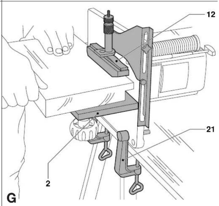
H

natural_image
Pure mechanical diagram showing a lever and pivot mechanism without any text or symbols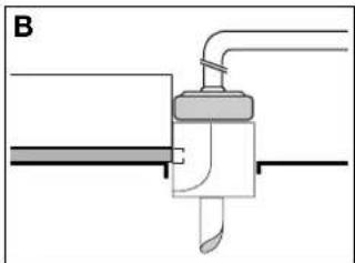
natural_image
Pure mechanical diagram showing a lever and pivot component without any text or symbols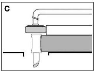
natural_image
Pure mechanical diagram showing a lever and shaft assembly without any text, numbers, or symbols|
J
Dansk 1
Deutsch 4
English 7
Español 10
Français 13
Italiano 16
Nederlands 19
Norsk 22
Português25
Suomi 28
Svenska 31
Ελληνικα 34
HÅNDFRÆSERBORD TILBEH∅RSUDSTYR DE6900
Tillykke!
You have chosen a DeWALT product. Years of experience, thorough product development and innovation make DeWALT one of the most reliable partners for professional users.
Table of contents
| Technical data en - 1 |
| Manufacturer's declaration en - 1 |
| Safety instructions en - 1 |
| Package contents en - 2 |
| Description en - 2 |
| Assembly and adjustment en - 2 |
| Instructions for use en - 2 |
| Maintenance en - 3 |
| Guarantee en - 3 |
Technical data
| DE6900 | |
| Router table (width x depth) mm 240 x 210 | |
| Side fence mm 240 x 135 | |
| Max. cutter diameter mm 35 | |
| Work height | mm 275 |
| Weight | kg 2.8 |
The following symbols are used throughout this manual:

Denotes risk of personal injury, loss of life or damage to the tool in case of non-observance of the instructions in this manual.

Denotes risk of electric shock.
Manufacturer's Declaration

DE6900
DeWALT declares that the attachment mentioned above has been designed in compliance with 89/392/EEC.
This attachment must not be put into service until it is established that the Power Tool to be connected to it is in compliance with 89/392/EEC (identified by the CE-marking on the Power Tool).
Director Engineering & Product Development Horst Großmann

Observe the safety regulations in the instruction manual of the Power Tool to be connected to this attachment. Also observe any applicable additional safety rules. Read the following safety instructions before attempting to operate this product.
Keep these instructions in a safe place!
The attention of UK users is drawn to the “woodworking machines regulations 1974” and any subsequent amendments.
General
• Always mount the Router Table in conformity with the present instructions.
- Keep children away.
- Dress properly. Do not wear loose clothing or jewellery. They can be caught in moving parts. Preferably wear rubber gloves and non-slip footwear when working outdoors. Wear protective hair covering to keep long hair out of the way.
- Do not use the Router Table outdoors in the rain or in a damp environment.
- The Router Table must be stable at all times.
- Keep the work top clear of foreign objects.
- Use the Router Table with the Power Tools and accessories specified in this manual only.
- Secure the Power Tool carefully.
- For stationary use, we recommend the application of a no volt release switch (e.g. 115 V: DE6781, 230 V: DE6782).
- Remove any nails, staples and other metal parts from the workpiece. - Use sharp and undamaged accessories only.
- Before operation, inspect the Router Table, the Power Tool, the cable and the plug carefully for signs of damage. Have any damage repaired by an authorized DeWALT repair agent before using the tool or Router Table.
- Keep the Router Table clean and in good condition for better and safer performance. Follow the instructions for maintenance. Keep all controls dry, clean and free from oil and grease.
- The workpiece must be properly supported at all times. For larger workpieces, we recommend to integrate the DE6900 Router Table in a larger table top.
- As woodworking produces dust and woodchips, the use of dust extraction equipment is recommended. A dust extraction adaptor is available as an option (DE6901).
- This Router Table is in accordance with the relevant safety regulations. To avoid danger, it must only be repaired by qualified technicians.
Additional safety rules for cutters
- Always use cutters with a shank diameter corresponding to the size of the collet installed in your tool.
- Always use cutters suitable for a speed of 30.000 ~min^-1 and marked accordingly.
- Never use cutters with a diameter exceeding the maximum diameter indicated in the technical data.
Package contents
The package contains:
1 Table Top
1 Side fence
1 Knob handle
2 Vice clamps
2 Side fence bars
4 Legs
1 Pressure pad assembly
1 Cutting depth fine adjuster DE6956
1 Trammel bar
1 Copy follower
1 Thrust block
1 Router position adjuster
1 Instruction manual
1 Exploded drawing
- Check for damage to the tool, parts or accessories which may have occurred during transport.
- Take the time to thoroughly read and understand this manual prior to operation.
Description (fig. A)
Your Router Table has been designed to extend the versatility of your DeWALT DW613, DW620, DW621, Elu MOF96(E) or Elu OF97(E) router.
1 Table top
2 Side fence
3 Side fence bar
4 Side fence locking bolt
5 Locking knob for side fence bar
6 Locking knob for guide rods
7 Leg
8 Leg fixing plate and screw
9 Leg fixing bolt
10 Pressure pad bracket
11 Pressure pad adjuster
12 Pressure pad
13 Knob handle
No-volt release switch
A no-volt release switch is available as an option (DE6783). It offers the following advantages:
- Optimum safety: It prevents the machine from restarting inadvertently in the event of a power loss.
- It allows easier access for switching of the router ON and OFF.
Assembly and adjustment

Do not mount any Power Tools other than the DEWALT DW613, DW620, DW621, Elu MOF96(E) or Elu OF97(E).
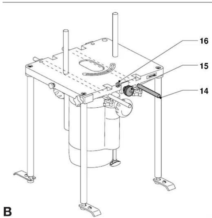
Assembling the attachment and mounting the router (fig. A & B)
The screws and nuts required to assemble the attachment are supplied with the Router Table.
- Place the table top (1) upside down on a flat surface.
- Mount your router to the table top using the guide rods (14) of your router as shown. Mount the router position adjuster (15).
- Tighten all guide rod locking knobs (6) and the nut (16) of the router position adjuster (15).
- For stationary use, assemble the legs (7) and mount the unit to a worktop using the leg fixing plates (8).
- If required, assemble the side fence (2) using the side fence bars and corresponding washers, the knob handle (13) and mount the pressure pad assembly (10, 11 & 12) as shown.
Mounting the dust extraction adaptor (option) (fig. C)
- Slacken the side fence locking bolt (4), slightly lift the side fence (2) and place the dust extraction adaptor (17) as shown.
Instructions for use

Always observe the safety instructions and applicable regulations.
Prior to operation:
- Check that the Power Tool is mounted as described above.
- Check that all guards and fences are in perfect working order and mounted correctly.
- Connect a dust extractor (if possible).
- Set the required depth of cut (refer to the instruction manual of your router).
- Mind the direction of feed (indicated by the arrows on the table).
Switching ON and OFF (fig. A)

- Refer to the instruction manual of your Power Tool.
When using a no-volt release switch (option)
- Press the ON/OFF-switch of your router.
- Lock the Power Tool in ON-position.
- Lift the plug cover and plug in the Power Tool.
- Connect the Router Table to the mains by plugging an extension cable into the connector of the no-volt release switch.
- To switch the router ON, press the green button of the no-volt release switch.
- To switch the router OFF, press the red button of the no-volt release switch.
Using the router with the attachments as a hand-held tool
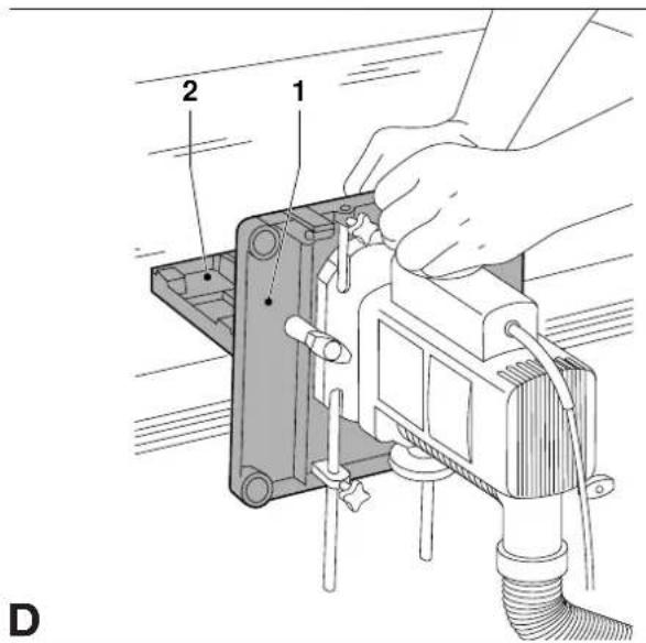
Router with right angle fence (fig. D)
In this configuration the cut is made by the side flutes of the cutter. This is ideal for trimming, moulding or rabetting workpieces which are too large to bring to the table.
- Use the table top (1) and side fence (2) to act as a large angle base.
- Guide the router and the attachments using both hands as shown.
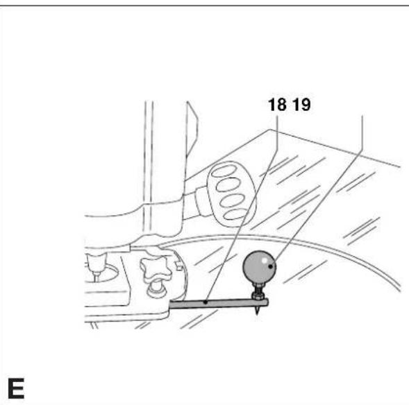
Router with trammel bar (fig. E)
The trammel bar (18) is used to make accurate circular cuts and decorative radius work.
- Remove the guide rods and install the trammel bar as shown.
- Press the trammel bar pin in the work surface and set the required radius.
- Guide the router with one hand while holding the center point (19) of the trammel bar firmly with the other.
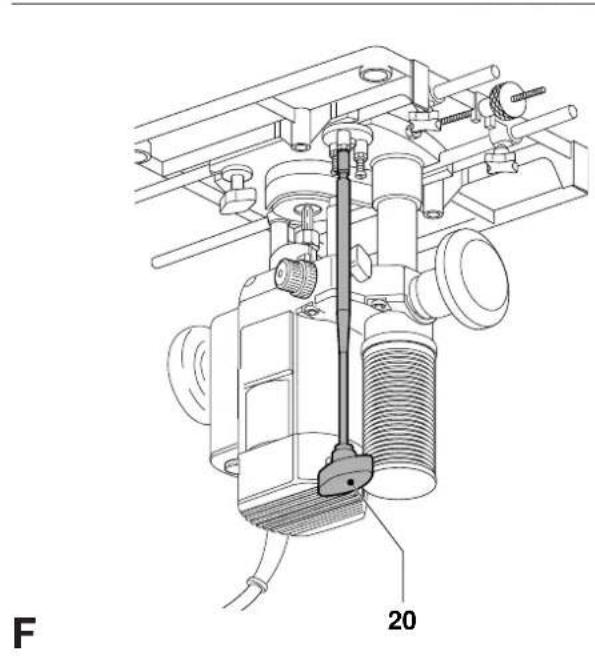
Using the router with the attachments as a stationary tool (fig. F)
- Mount the router onto the table as described above.
- Remove the depth adjuster of your router and replace it by the cutting depth fine adjuster DE6956 (20). Screw the depth adjuster onto the revolver depth stop.

Make sure the Router Table is stable at all times.
Router mounted laterally on the workbench (fig. G)
This configuration is particularly useful for light and small workpieces.
• Install the router using the vice clamps (21) as shown.
- Guide the workpiece along the side fence (2), preferably using the pressure pad (12).

Feed the workpiece as indicated by the arrow on the side of the table.
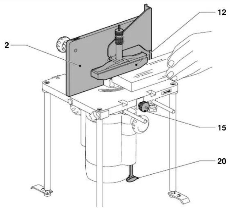
Spindle moulding (fig. A)
For spindle moulding applications, the router is installed in the inverted position. The Router Table is mounted securely using the legs (7) and the fixing plates (8).
Spindle moulding using the side fence (fig. H)
- Position the cutter horizontally using the router position adjuster (15).
- Adjust the depth of cut using the cutting depth fine adjuster DE6956 (20).
- Guide the workpiece along the side fence (2), preferably using the pressure pad (12).

Feed the workpiece as indicated by the arrow on the side of the table.
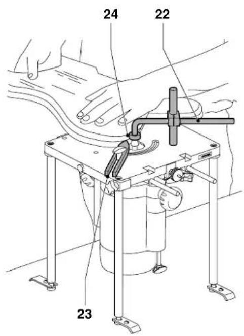
Using the copy follower and thrust block (fig. I)
The copy follower (22) allows the user to work without the large fence (2) (freehand routing).
- Mount the copy follower (22) and the thrust block (23) as shown.
- Put the ball bearing guide (24) in the correct position above the cutter.
- Tighten all knobs securely.
- With the router OFF, try a practice run to make sure that all points can be moulded as required.
The thrust block (23) ensures your workpiece is always guided to the correct side of the cutter.
Using a template
- Position the ball bearing (24) over the cutter, making sure the centres of the two are in line.
- Prepare a template. The difference between bearing and cutter diameter corresponds to the difference between workpiece and template dimensions.
- Secure the template to the workpiece using double-sided tape.
- With the router OFF, try a practice run to make sure that all points can be moulded as required.
For the correct position of the ball bearing (24), refer to fig. J:
- A Edge moulding with bearing off-centre.
- B Trimming facing material flush to edge of workpiece with a trimming cutter.
• C Edge moulding following template contour.
Maintenance
Your D=WALT attachment has been designed to operate over a long period of time with a minimum of maintenance. Continuous satisfactory operation depends upon proper tool care and regular cleaning.

Lubrication
Your attachment requires no additional lubrication.

Cleaning
Regularly clean the attachment with a soft cloth.

Unwanted products and the environment
Take your attachment to an authorized DeWALT repair agent where it will be disposed of in an environmentally safe way.
GUARANTEE
• 30 DAY NO RISK SATISFACTION GUARANTEE •
If you are not completely satisfied with the performance of your DeWALT tool, simply return it within 30 days, complete as purchased, to a participating Dealer, or an authorized DeWALT repair agent, for a full refund or exchange. Proof of purchase must be produced.
• ONE YEAR FREE SERVICE CONTRACT •
If you need maintenance or service for your D≡WALT tool, in the 12 months following purchase, it will be undertaken free of charge at an authorized D≡WALT repair agent. Proof of purchase must be produced. Includes labour and spare parts for the attachments. Excludes accessories.
• ONE YEAR FULL WARRANTY •
If your D=WALT product becomes defective due to faulty materials or workmanship within 12 months from the date of purchase, we guarantee to replace all defective parts free of charge or, at our discretion, replace the unit free of charge provided that:
• The product has not been misused.
• Repairs have not been attempted by unauthorized persons.
• Proof of purchase date is produced.
This guarantee is offered as an extra benefit and is additional to consumers statutory rights.
For the location of your nearest authorized DeWALT repair agent, please use the appropriate telephone number on the back of this manual.
Director Engineering & Product Development Horst Großmann
X. fopsmann
L'emballage contient:
1 Table de travail
1 Guide parallèle
1 Poignée
2 Serre-joints
KIT DI ACCESSORI DE6900
Congratulazioni!
Director Engineering & Product Development
Horst Großmann

DW620, DW621, Elu MOF96(E) of Elu OF97(E).
Manufacturer's Declaration

DE6900
Director Engineering & Product Development Horst Großmann

DeWALT, Richard-Klinger-Straße 40, D-65510, Idstein, Tyskland
Sikkerhetsforskrifter
2 Pinner for sideskjerm
4 Ben
3 Pinner for sideskjerm
Director Engineering & Product Development Horst Großmann
X. Jopman
DEWALT, Richard-Klinger-Straße 40, D-65510, Idstein, Alemanha
Director Engineering & Product Development Horst Großmann

Director Engineering & Product Development Horst Großmann

DeWALT, Richard-Klinger-Straße 40, D-65510, Idstein, Tyskland