CFUE2021AW - Freezer Crosley - Free user manual and instructions
Find the device manual for free CFUE2021AW Crosley in PDF.


| Product Type | Combined Refrigerator-Freezer |
| Brand | Crosley |
| Model | CFUE2021AW |
| Power Supply | 115 V, 60 Hz, 15 A, AC |
| Refrigerant | Flammable (type not specified) |
| Automatic Ice Maker | Yes (optional on some models) |
| Ice Production Capacity | Approximately 2 to 2.5 lb (0.9 to 1.1 kg) per 24 hours |
| Shelves | Adjustable tempered glass shelves |
| Door Bins | Fixed door bins, can hold gallon containers |
| Deli Drawer | Available (depending on model) |
| Crisper Humidity Control | Yes, adjustable |
| Air Filter | PureAir™ RAF-1 activated carbon filter (replace every 6 months) |
| Lighting | LED bulb 5 W max |
| Door Reversal Possible | Yes, from left to right or vice versa |
| Water Connection | Requires braided stainless steel hose (pressure 30-100 psi) |
| Operating Ambient Temperature | Between 3°C and 43°C (38°F to 110°F) |
| Cleaning | Clean interior with baking soda and water; do not use abrasive cleaners |
| Safety | Use of flammable refrigerant; do not use mechanical devices to defrost |
| Warranty | One-year limited warranty (parts and labor) |
Frequently Asked Questions - CFUE2021AW Crosley
User questions about CFUE2021AW Crosley
0 question about this device. Answer the ones you know or ask your own.
Ask a new question about this device
Download the instructions for your Freezer in PDF format for free! Find your manual CFUE2021AW - Crosley and take your electronic device back in hand. On this page are published all the documents necessary for the use of your device. CFUE2021AW by Crosley.
USER MANUAL CFUE2021AW Crosley
Safety Important Information....2
Features....5
Installation....6
Door Removal....8
Door Handle Installation....12
Water Supply Connection.... 16
Ice Maker.... 18
Controls and Settings....19
Storage Features.... 20
Normal Operating Sounds.... 22
Filter Replacement....23
Care and Cleaning.... 24
Troubleshooting.... 26
Limited warranty....28
Welcome to our family
Thank you for bringing Conservator into your home! We see your purchase as the beginning of a long relationship together.
This manual is your resource for the use and care of your product. Please read it before using your appliance. Keep it handy for quick reference. If something doesn't seem right, the troubleshooting section will help you with common issues.
FAQ, helpful tips and videos, cleaning products, and kitchen and home accessories are available at
www.Frigidaire.com.
We are here for you! Visit our website, chat with an agent, or call us if you need help. We may be able to help you avoid a service visit. If you do need service, we can get that started for you.
Let's make it official! Be sure to register your product.
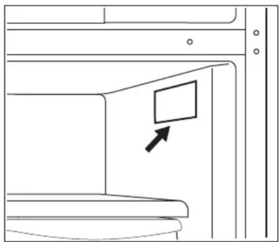
Keep a record for quick reference
Model number
Serial number
Purchase date
natural_image
Line drawing of a cabinet interior with a directional arrow pointing to the front panel (no text or symbols)Serial Number Location

WARNING!
You must follow these guidelines to ensure that your refrigerator's safety mechanisms are operating correctly.
Safety Definitions

This is the safety alert symbol. It is used to alert of potential personal injury hazards. Obey all safety messages that follow this symbol to avoid possible injury or death.

DANGER
DANGER indicates an imminently hazardous situation which, if not avoided, will result in death or serious injury.

WARNING!
WARNING indicates a potentially hazardous situation which, if not avoided, could result in death or serious injury.

CAUTION!
CAUTION indicates a potentially hazardous situation which, if not avoided, may result in minor or moderate injury.

IMPORTANT
IMPORTANT indicates installation, operation or maintenance information which is important but not hazard-related.

DANGER

DANGER Risk of fire or explosion. Flammable refrigerant used. Do not use mechanical devices to defrost refrigerator. Do not puncture refrigerant tubing.
DANGER Risk of fire or explosion. Flammable refrigerant used. To be repaired only by trained service personnel. Use only manufacturer-authorized service parts. Any repair equipment used must be designed for flammable refrigerants. Follow all manufacturer repair instructions. Do not puncture refrigerant tubing.

CAUTION!

CAUTION Risk of fire or explosion. Dispose of refrigerator properly in accordance with the applicable federal or local regulations. Flammable refrigerant used.
CAUTION Risk of fire or explosion due to puncture of refrigerant tubing. Follow handling instructions carefully. Flammable refrigerant used.

WARNING!
CALIFORNIA RESIDENTS ONLY
WARNING! Cancer and Reproductive Harm
www.P65Warnings.ca.gov
Child Safety
This appliance is not intended for use by persons (including children) with reduced physical, sensory or mental capabilities, or lack of experience and knowledge, unless they have been given supervision or instruction concerning use of the appliance by a person responsible for their safety.
Destroy or recycle the carton, plastic bags, and any exterior wrapping material immediately after the refrigerator is unpacked. Children should never use these items to play. Cartons covered with rugs, bedspreads, plastic sheets or stretch wrap may become airtight chambers, and can quickly cause suffocation.
IMPORTANT SAFETY INSTRUCTIONS
Do not store or use gasoline or other flammable vapors and liquids in the vicinity of this or any other appliance.
Do not store explosive substances such as aerosol cans with a flammable propellant in this appliance.
Do not operate the refrigerator in the presence of explosive fumes
Avoid contact with any moving parts of automatic ice maker.
Remove all staples from the carton. Staples can cause severe cuts, and also destroy finishes if they come in contact with other appliances or furniture.

WARNING!
Do not use electrical appliances inside the food storage compartments of the appliance unless they are of the type recommended by the manufacturer.
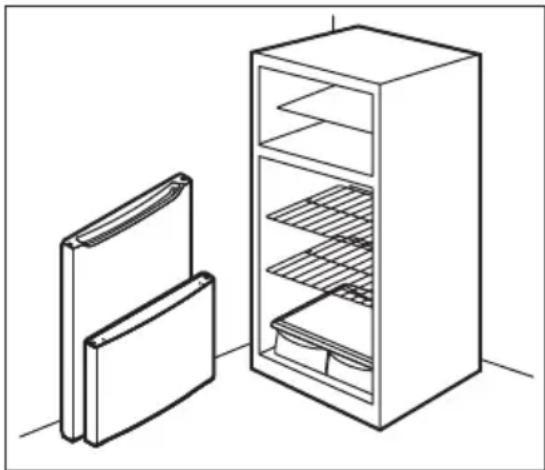
are getting rid of your old refrigerator or freezer, follow the instructions below to help prevent accidents.
We strongly encourage responsible appliance recycling/disposal methods. Check with your utility company or visit www.energystar.gov/recycle for more information on recycling your old refrigerator.
Before you throw away your old refrigerator/freezer:
- Remove doors.
- Leave shelves in place so children may not easily climb inside.
- Have it removed by a qualified service technician.
natural_image
Line drawing of a refrigerator with two open storage compartments (no text or symbols)
IMPORTANT
CFC/HCFC Disposal
Your old refrigerator may have a cooling system that used CFCs or HCFCs (chlorofluorocarbons or hydrochlorofluorocarbons). CFCs and HCFCs are believed to harm stratospheric ozone if released to the atmosphere. Other refrigerants may also cause harm to the environment if released to the atmosphere.
If you are throwing away your old refrigerator, make sure the refrigerant is removed for proper disposal by a qualified technician. If you intentionally release refrigerant, you may be subject to fines and imprisonment under provisions of environmental legislation.
Proper Disposal of your Refrigerator or Freezer
Risk of child entrapment
Child entrapment and suffocation are not problems of the past. Junked or abandoned refrigerators or freezers are still dangerous – even if they will sit for “just a few days”. If you
Electrical information

IMPORTANT
Pressing and holding the On/Off button for three seconds, located on the temperature control panel, will disable your refrigerator's cooling system but does not disconnect the power to the light bulb and other electrical components. To turn off power to your refrigerator you must unplug the power cord from the electrical outlet.

CAUTION!
To avoid personal injury or property damage, handle tempered glass shelves carefully. Shelves may break suddenly if nicked, scratched, or exposed to sudden temperature change.
- The refrigerator must be plugged into its own dedicated 115 Volt, 60 Hz., 15 Amp, AC only electrical outlet. The power cord of the appliance is equipped with a three-prong grounding plug for your protection against electrical shock hazards. It must be plugged directly into a properly grounded three prong receptacle. The receptacle must be installed in accordance with local codes and ordinances. Consult a qualified electrician. Avoid connecting refrigerator to a Ground Fault Interrupter (GFI) circuit. Do not use an extension cord or adapter plug.
- If the power cord is damaged, it should be replaced by an authorized service technician to prevent any risk.
- Never unplug the refrigerator by pulling on the power cord. Always grip the plug firmly, and pull straight out from the receptacle to prevent damaging the power cord.
- Unplug the refrigerator before cleaning and before replacing a light bulb to avoid electrical shock.
- Performance may be affected if the voltage varies by 10% or more. Operating the refrigerator with insufficient power can damage the compressor. Such damage is not covered under your warranty.
- Do not plug the unit into an electrical outlet controlled by a wall switch or pull cord to prevent the refrigerator from being turned off accidentally.

WARNING!
Do not, under any circumstances, cut, remove, or bypass the grounding prong (A). Always use the power cord with 3-prong grounded plug and grounding type wall receptacle.

natural_image
Diagram showing a plug socket with two slots and a labeled connector (A), no text or symbols present.
IMPORTANT
*Features may vary by model.
Accessories are available for your appliance and may be purchased at Frigidaire.com or by calling toll-free 1-866-831-2306.
Product overview
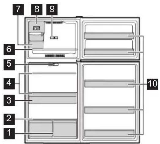
2 Crisper Cover
3 Deli Drawer*
4 Full Shelves
5 Refrigerator Control
6 Freezer Shelf
7 Ice Bin*
8 Freezer Control
9 Ice Maker*
10 Fixed Door Bins
1 Crispers
This User Manual provides general installation and operating instructions for your model. We recommend using a service or kitchen contracting professional to install your appliance. Use the appliance only as instructed in this User Manual. Before starting the appliance, follow these important first steps.

Installation Checklist
Doors
□ Handles are secure and tight (some models)
☐ Refrigerator door seals completely to the cabinet on all sides
☐ Freezer door is level from side to side across the top
Leveling
☐ Appliance is level side-to-side and tilted 1/4" (6 mm) front-to-back
□ Cabinet is setting solid on all corners
□ Anti-tip bracket set in front on both sides
Electrical Power
□ House power is turned on
□ Appliance is plugged in
Ice Maker
☐ House water supply is connected to the appliance

WARNING!
Potable water supply only.
☐ No water leaks present in any connections - recheck in 24 hours
☐ Ice maker is turned on
Final Checks
□ Shipping material is removed
☐ Refrigerator and freezer temperatures are set
□ Crisper humidity controls are set
□ Registration card is sent in
Tools necessary
These tools are necessary at different stages of the installation process:
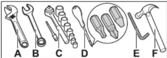
A. Adjustable Wrench
B. 5/16" Fixed Wrench
C. Socket Wrench
A. Adjustable Wrench
B. 5/16" Fixed Wrench
C. Socket Wrench
D. Screwdriver: Multi-bit with #2 Square Bit and Flat Head
E. 6 mm Allen Wrench
F. Hammer

Components Provided
A. Top hinge screw MSX16 Quadrex
B. Center hinge
C. Pan Head Quadrex MSX12
Cleaning the appliance

IMPORTANT
Remove tape and glue residue from surfaces before turning the appliance on. Rub a small amount of liquid dish soap over the adhesive with your fingers. Rinse with warm water and dry with a soft cloth.
Do not use sharp instruments, rubbing alcohol, flammable fluids, or abrasive cleaners to remove tape or glue. These products can damage the surface of the appliance.
After you remove all of the package materials, clean the inside of the appliance before using it. Refer to Care and Cleaning.
Moving the appliance

IMPORTANT
The appliance is heavy. When moving the appliance for cleaning or service, raise the anti-tip bracket (refer to Setting the anti-tip brackets). Be sure to cover the floor with cardboard or hardboard to avoid floor damage. Always pull the appliance straight out when moving it. Do not wiggle or “walk” the appliance when trying to move it as you could damage the floor.
Location
- Choose a place that is near a grounded, non-GFCI, electrical outlet. Do not use an extension cord or an adapter plug.
- If possible, place the appliance out of direct sunlight and away from the range, dishwasher, or other heat sources.
- The appliance must be installed on a floor that is level and strong enough to support a fully loaded appliance.
- Consider water supply availability for models equipped with an automatic ice maker.

WARNING!
This appliance is intended for use in residential household and similar interior applications such as:
- Kitchen / kitchenette
- Pantry room
- Basement
- Enclosed garage
- Other interior residential type environments

CAUTION!
Do not install the appliance where the temperature will drop below 38^ F ( 3^ C) or rise above 110^ F ( 43^ C). The compressor will not be able to maintain proper temperatures inside the appliance.

NOTE
Do not block the lower front of the appliance. Sufficient air circulation is essential for the proper operation of the appliance.

WARNING!
Allow the following clearances for ease of installation, proper air circulation, and plumbing and electrical connections:
• Sides and top 3/8" (9.5 mm)
- Back 1" (25.4 mm)

NOTE
If you place the appliance with the door hinge side against a wall, you may have to allow additional space so the door can be open wider.
Cabinet leveling and door alignment
Guidelines for final positioning of appliance:
- All 4 corners of the cabinet must rest firmly on the floor.
- The cabinet should be level at the front and rear.
- The sides should tilt 1/4" (6 mm) from front to back to ensure that doors close and seal properly.
- Align the doors with each other and level them.
Setting the anti-tip brackets
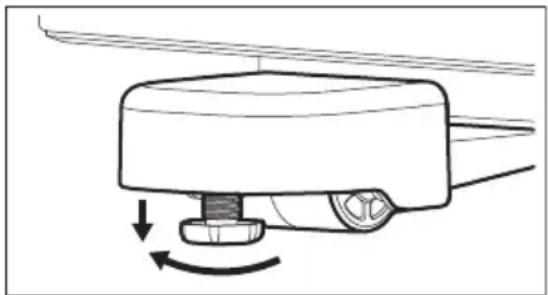
The anti-tip brackets are located on the lower front corners of the cabinet. Lower the anti-tip brackets on each side clockwise until they contact the floor. Do not raise the cabinet.
natural_image
Diagram of a mechanical device with rotating components and directional arrows indicating motion (no text or symbols)
NOTE
The anti-tip bracket must be installed according to the instructions in the User Manual. Failure to do so may result in injury.
Mullion
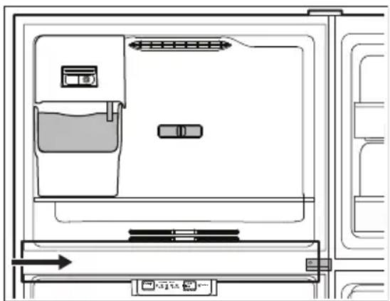
When you first turn on the appliance, the mullion might be warm to the touch for the first 24 hours of operation. This is normal.
natural_image
Line drawing of a refrigerator interior with door, drawer, and side panel (no text or symbols)Door Removal

CAUTION!
Before you begin, turn the appliance temperature control to OFF and remove the electrical power cord from the wall outlet. Remove any food from door shelves.

NOTE
The direction in which the appliance doors open (door swing) can be reversed, from left to right or right to left, by moving the door hinges from one side to the other. Reversing the door swing should be performed by a qualified person.

NOTE
We do not recommend to use an electric tool to unscrew and screw parts because it may damage the screw threads or cause screw heads to be stripped off.

NOTE
Keep the screws so they can be used on the opposite side.
- Unplug the appliance.
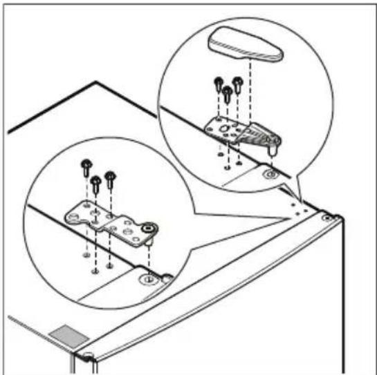
- Remove the top hinge cover (some models).
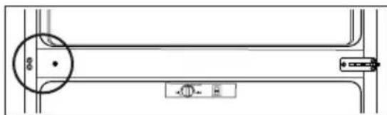
- Using a 5/16" socket, remove the 3 screws from the hinge. Remove the tape covering the top hinge holes on the opposite side of the appliance. Remove the top hinge.
natural_image
Technical diagram showing mechanical assembly with two circular insets highlighting components (no text or symbols present)- Carefully open the freezer door, and lift the door off of the center hinge pin. Set the door aside.

CAUTION!
Place the doors on a padded surface to avoid damage where they cannot fall and cause personal injury.
- Unscrew the center hinge pin using an adjustable wrench and set it aside.
- Open the refrigerator door and lift the door off of the bottom hinge pin. Set the door aside.
- Remove the 3 pan head screws using a multi-bit screwdriver with a #2 square bit.
natural_image
Technical line drawing of a mechanical component with no visible text or symbols- Remove the 3 screws from the center hinge using a multi-bit screwdriver with a #2 square bit. Flip the center hinge over and install it on the left side of the unit.
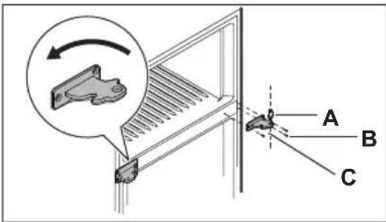
A. Hinge pin
B. Screws
C. Center hinge
- Install the 3 pan head screws on the right side.

natural_image
Pure technical line drawing of a mechanical or electrical component without any text, numbers, or symbols- Remove both lower hinge covers if installed.
-
Remove the screw from the door stopper with a multi-bit screwdriver with a #2 square bit.
-
Unscrew the bottom hinge pin from the right-hand position using an adjustable wrench.
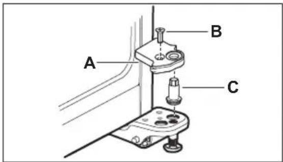
A. Door Stopper
B. Door Stopper Screw
C. Bottom Hinge Pin
- Install the bottom hinge pin in the left-hand hole of the left-hand lower hinge.
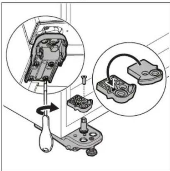
- With the assistance of another person, tilt the appliance back, to have access to the bottom hinge. Loosen the hinge screws slightly. Flip the door stopper, and place it on top of the bottom hinge, making adjustments until the stopper is flush against the unit. Tighten all screws.
natural_image
Mechanical assembly diagram showing a tool interacting with internal components, including a close-up of a mechanical part (no text or symbols visible)Door reversal
- With a flathead screwdriver, pry out the center hinge bearing plug from the left side of the refrigerator door and discard.
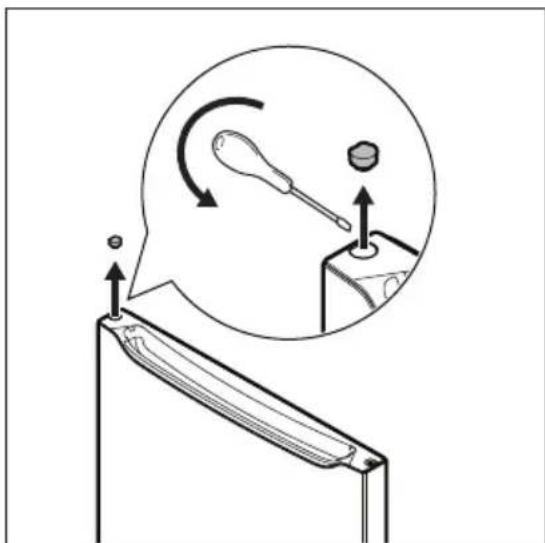
- Remove the new left side hinge bearing from the literature bag and install it on the left side by tapping it with a hammer until it is flush with the end cap.
- Reverse the door handle if applicable (refer to Door Handle Installation).
- Flip the refrigerator door over and remove the screw from the auto-closer hook using a multi-bit screwdriver with a #2 square bit ans set it aside.
- Pry out the hinge bearing from the door with a flat head screwdriver.
- Install the bottom hinge bearing on the opposite side of the door. Flip the autocloser hook over and install on the opposite side of the door.
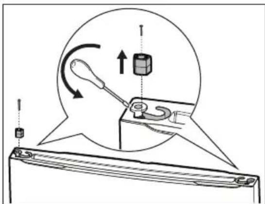
natural_image
Diagram showing a mechanical assembly with a tool and spring, no text or symbols present- Repeat steps 1-6 for the freezer door.
-
Lower the refrigerator door in the opened position on the bottom hinge pin and close the door.
-
Screw in and tighten the center hinge pin using an adjustable wrench.
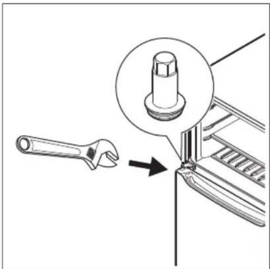
natural_image
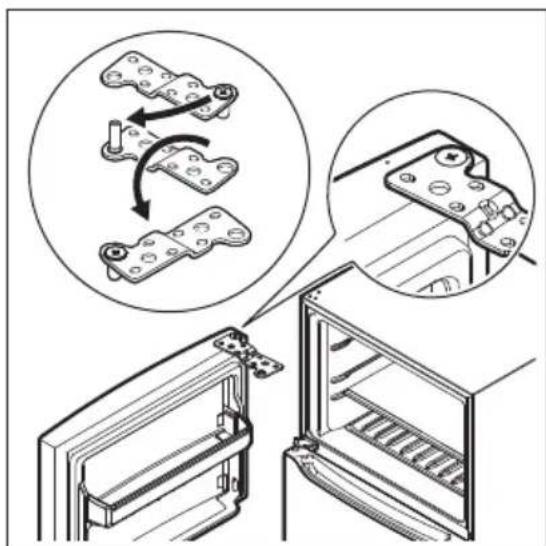
Diagram showing a wrench interacting with a mechanical component, highlighting a bolt detail (no text or symbols present)- For type A top hinge, attach the top hinge to the freezer door. Lower the freezer door over the center hinge pin at a 90° angle, and close the door, holding it in place.
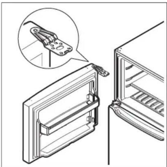
natural_image
Technical line drawing of a refrigerator with an inset showing a mechanical clamp mechanism (no text or symbols)Type A hinge
- For type B top hinge, remove the hinge pin from the top hinge. Put the hinge pin through the hole on the opposite side. Flip the top hinge over and attach it to the freezer door. Lower the freezer door over the center hinge pin at a 90° angle, and then close the door, holding it in place.
natural_image
Diagram showing mechanical assembly steps with magnified views of internal components (no text or symbols)Type B hinge
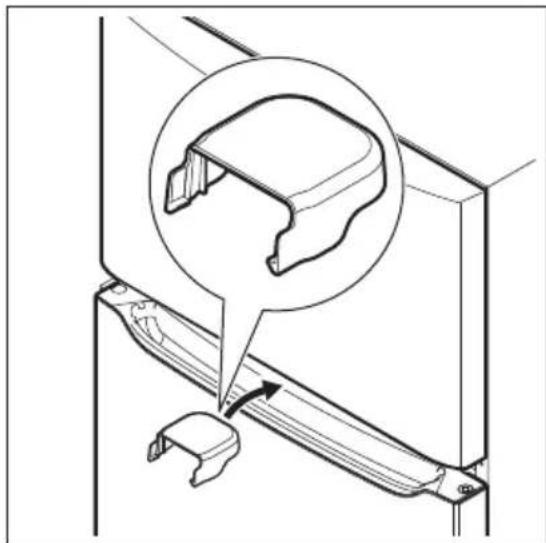
- Place the lower hinge cover between the freezer door and refrigerator door to keep it level while attaching the top hinge.
natural_image
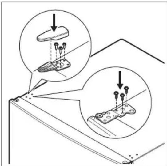
Technical line drawing of a mechanical bracket with an inset showing a close-up of a component (no text or symbols present)- Align the top hinge to the holes on the unit and attach screws with 5/16" socket, then place the top hinge cover on the unit (some models).
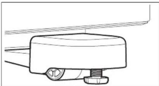
- Replace the lower hinge covers.
natural_image
Technical line drawing of a mechanical component with no visible text or symbols
CAUTION!
Wear gloves and safety goggles. Use extreme caution when installing these handles. The rounded end of the handles may be sharp (some models).
Metal handle
To attach the refrigerator/freezer metal handle:
-
Open the door.
-
Place the rounded part of the handle onto the shoulder screw on the face of the door and align the 2 holes:
• for the refrigerator: at the top of the handle with the 2 holes at the top of the door.
• for the freezer: at the bottom of the handle with the 2 holes at the bottom of the door.
Do not tighten the set screw yet.
- Install the 2 screws into:
• the top of the refrigerator handle:
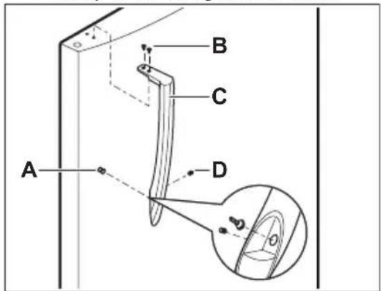
A. Shoulder screw
B. Screw
C. Handle
D. Set screw
• the bottom of the freezer handle:
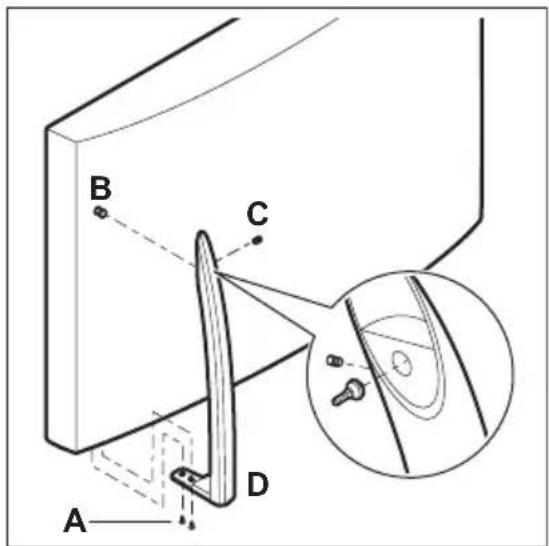
A. Screw
B. Shoulder screw
C. Set screw
D. Handle
- Tighten the set screw on the rounded part of the handle until the handle is flush with the door, then tighten another 1/2 turn
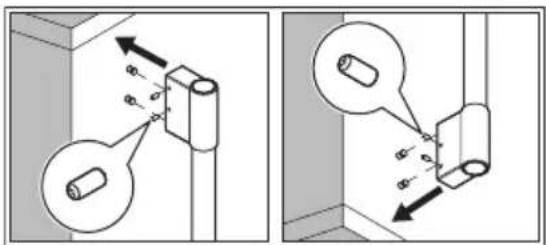
For professional models:
With the door open, place the handle over the shoulder screw. Tighten the set screws.
natural_image
Technical diagrams showing mechanical assembly with cylindrical components and directional arrows (no text or symbols)Plastic handle
To attach the refrigerator/freezer plastic handle:
- Open the door.
- Place the end of the handle on the mounting screw and pull it:
- for the refrigerator: down to secure it in place.
• for the freezer: up to secure it in place.
- Align the handle base with the holes:
- in top of the door for the refrigerator handle.
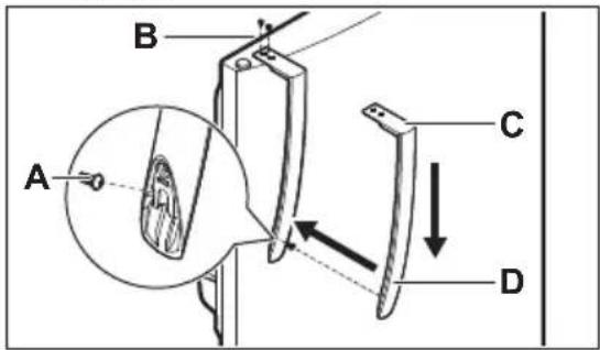
A. Mounting screw
B. Screws
C. Handle base
D. Handle
- in the bottom of the door for the freezer handle.
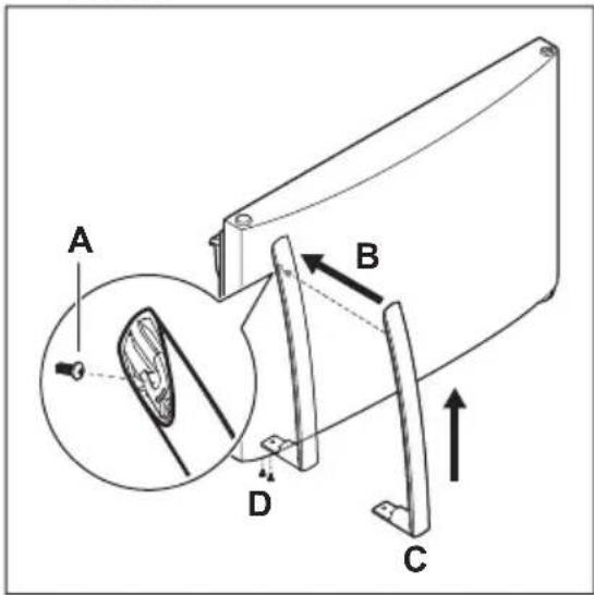
A. Mounting screw
B. Handle
C. Handle base
D. Screws
- Install screws packaged with the handle.
Door handle reversal

CAUTION!
Ensure the doors are set aside in a secure position where they cannot fall and cause personal injury.
Reverse and attach the freezer and refrigerator handles as shown. The handles may be easier to reverse while the doors are off.
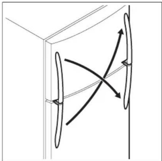
natural_image
Pure diagram of curved arrows inside a 3D rectangular frame, no text or symbols presentUnscrew and remove the handles.

natural_image
Pure diagram of a curved pipe or duct with directional arrows indicating flow or movement, no text or symbols present.To reverse the door handles:
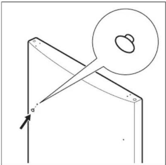
- Remove and discard the button plugs from the front of the refrigerator and freezer doors.
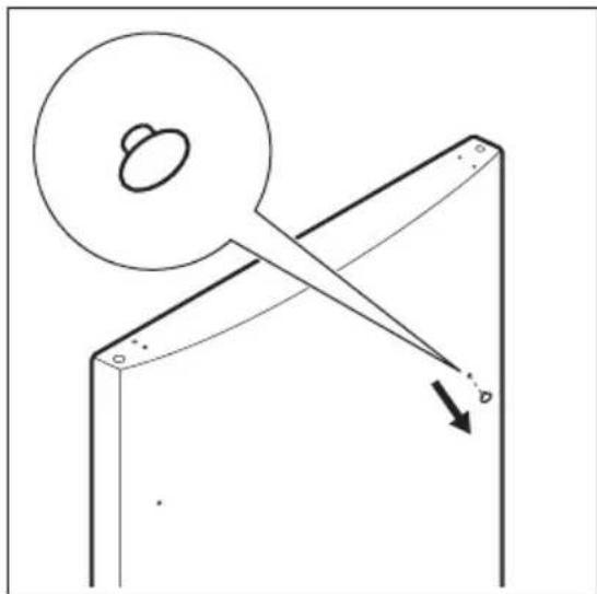
natural_image
Pure mechanical diagram showing a lever mechanism with a circular head and triangular supports, no text or symbols present.- Remove the screw using an adjustable wrench or multi-bit screwdriver (varies by model) and install it where the button plugs were removed on the opposite side of the door.
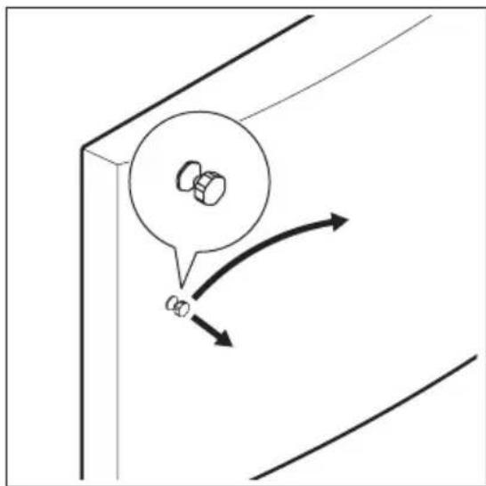
natural_image
Diagram showing a mechanical component with two rotating parts and directional arrows indicating motion (no text or symbols)- Install the button plugs from the literature bag on the opposite side of the front of the refrigerator and freezer doors. Push firmly to ensure button plug is fully seated.
natural_image
Pure mechanical diagram showing a lever and gear assembly without any text, numbers, or symbolsTo install your specific handle, reference door handle installation on the previous pages.
Before Installing The Water Supply Line
Automatic ice makers are optional accessories that you may install in most models at any time. Visit Frigidaire.com for information about Ice Maker Kit 117000.

WARNING!
To avoid electric shock, which can cause death or severe personal injury, disconnect the appliance from the electrical power before connecting a water supply line to the appliance.

CAUTION!
To avoid property damage:
- User stainless steel braided tubing for the water supply line. Do not use water supply tubing made of 1/4" plastic. Plastic tubing greatly increases the potential for water leaks, and the manufacturer will not be responsible for any damage if you use plastic tubing for the supply line.
- Do not install water supply tubing in areas where temperatures fall below freezing.
- Chemicals from a malfunctioning softener can damage the ice maker. If the ice maker is connected to soft water, ensure that the softener is maintained and working properly.

IMPORTANT
Ensure your water supply line connections comply with all local plumbing codes.
You will need
- Basic tools: adjustable wrench, flat-blade screwdriver, and Phillips™ screwdriver.
- Access to a household cold water line with water pressure between 30 and 100 psi.
- A water supply line made of stainless steel tubing. To determine the length of tubing needed, measure the distance from the ice maker inlet valve at the back of the appliance to your cold water pipe. Then add approximately 6 ft (1.8 m) to ensure you can move the appliance for cleaning.
- A shutoff valve to connect the water supply line to your household water system. Do not use a self-piercing type shutoff valve.
- Do not reuse compression fitting or use thread seal tape.

NOTE
Check with your local building authority for recommendations on water lines and associated materials prior to installing your new refrigerator. Depending on your local/state building codes, Conservator recommends:
- for homes with existing valves its Smart Choice® water line kit 5304437642 with a 6 ft stainless steel water line.
- for homes without an existing valve, we recommend Smart Choice® water line kit 5304493869 with a 6 ft polyline waterline.
Please refer to Frigidaire.com for more information.
Installing the water supply line

NOTE
These instructions do not cover after market ice maker installation. Instructions in after market ice maker kit should be used.
To connect water supply line to ice maker inlet valve:
- Disconnect refrigerator from electric power source.
- Place end of water supply line into sink or bucket. Turn on water supply and flush supply line until water is clear. Turn off water supply at shutoff valve.
- Remove plastic cap from water valve inlet and discard cap.
-
Depending on the tubing you use:
-
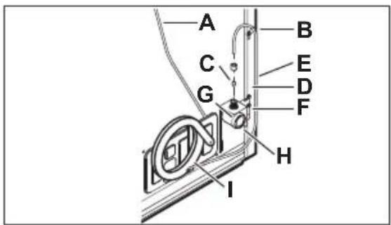
Copper tubing - Slide brass compression nut, then ferrule (sleeve) onto water supply line. Push water supply line into water valve inlet as far as it will go (1/4" / 6.4 mm). Slide ferrule (sleeve) into valve inlet and finger tighten compression nut onto valve. Tighten another half turn with a wrench; do not over tighten.
- Braided flexible stainless steel tubing - The nut is already assembled on the tubing. Slide nut onto valve inlet and finger tighten nut onto valve. Tighten another half turn with a wrench; do not over tighten.
-
With steel clamp and screw, secure water supply line to rear panel of the appliance.
-
Coil excess water supply line (copper tubing only), about 2.5 turns, behind refrigerator as shown and arrange coils so they do not vibrate or wear against any other surface. Do not kink tubing.
- Turn on water supply at shutoff valve and tighten any connections that leak.
- Reconnect refrigerator to electrical power source.
- Turn the ice maker on.

Copper tubing installation

Braided flexible stainless steel tubing installation
A. Plastic water tubing to ice maker fill tube
B. Steel clamp
C. Brass compression nut
D. Ferrule (sleeve)
E. Copper water line
F. Water valve bracket
G. Valve inlet
H. Water valve
I. Copper water line from household water supply*
J. Braided flexible stainless steel water line
K. 6 ft (1.8 m) braided flexible stainless steel water line from household water supply*
*Include enough tubing in the loop to allow moving the refrigerator out for cleaning.
Automatic ice maker

NOTE
Automatic ice makers are optional accessories that you may install in most models at any time. Visit Frigidaire.com for information about ice maker kit 117000.
If your appliance has an automatic ice maker, it will produce minimal ice during the first 24 hours of operation. Air in new plumbing lines may cause the ice maker to cycle 2 or 3 times before making a full tray of ice. With no usage, it will take approximately 1 to 2 days to fill the ice container.
New plumbing connections may cause the first production of ice cubes to be discolored or have an odd flavor. Discard the ice produced during the first 24 hours.

NOTE
The ice maker is shipped in the ON position. To ensure proper function for your ice maker, hook up the water supply immediately or turn the ice maker OFF. If the ice maker is on and the water supply is not connected, the water valve will make a loud chattering noise.
Turning ice maker on
After connecting the plumbing, open the water supply valve. Place the ice container under the ice maker, pushing it as far back as possible.
Press the ice maker's On/Off button.
Turning ice maker off
To stop the ice maker, press the ice maker's
On/Off ⏻ button. The ice maker regulates the ice production and stops making ice when full and starts again when ice is low in the ice container.
Ice production
The ice maker produces 2 to 2.5 lbs of ice every 24 hours depending on usage conditions. Ice is produced at a rate of 10 cubes every 100 to 160 minutes.

NOTE
Set the freezer to a colder setting to increase the output of the ice maker. Allow 24 hours for the temperature to stabilize.

NOTE
Do not place the ice container in a dishwasher.
Cool down period
To ensure safe food storage, allow the appliance to operate with the doors closed for at least 8 hours before loading it with food.

NOTE
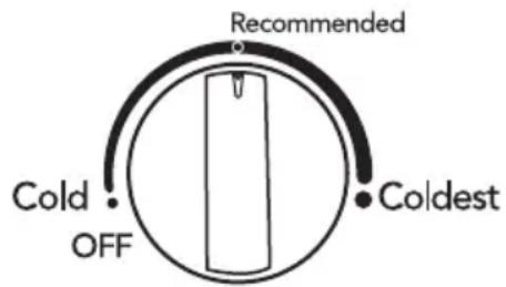
When first turning the appliance on, adjust the control to Recommended. After 24 hours, adjust the controls as needed.
Freezer control

All models

NOTE
If your appliance is in a garage or area where the temperature is below 50 °F, adjust the freezer control to the coldest setting to improve performance.
Refrigerator Controls
varies by model

NOTE
Adjusting the refrigerator temperature control to OFF turns off the compressor and prevents the refrigerator from cooling, but does not disconnect the power to the light bulb and other electrical components. To turn off power to your refrigerator, you must unplug the power cord from the wall outlet.
Temperature Adjustment
Adjust the temperature gradually: adjust the knobs in small increments, allowing the temperature to stabilize.
- For colder temperatures, adjust the control toward Coldest.
- For warmer temperatures, adjust the control toward Cold.
Adjusting the refrigerator control will change temperatures in both compartments. The freezer control can be left at the factory preset (Recommended) or adjusted as desired.
To maintain temperature, a fan circulates air in the refrigerator and freezer compartments. For good circulation, do not block cold air vents with food items.
Door Storage
Door bins, shelves, and racks conveniently store jars, bottles, and cans. You can quickly select frequently used items.
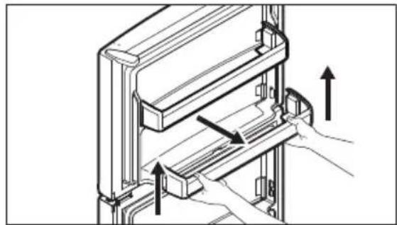
Door Bin
Door bins can accommodate gallon-sized plastic drink containers and economy-sized jars and containers.
-
Lift up the bin.
-
Pull it straight out.
-
Push the bin back and down into the locking tabs.
-
The bin sides will lock into the tabs.
natural_image
Technical diagram of a mechanical assembly with directional arrows indicating movement or force (no text or symbols present)Shelf adjustment
The shelves are easy to adjust to suit individual needs. Before adjusting the shelves, remove all food.
To adjust shelves, slide the shelf by moving it forward and lifting it upward.
To replace shelves, insert the rear of the shelf into any pair of shelf rails and carefully push the shelf back into position, making sure the shelf clips (A) go in the notch in the liner.
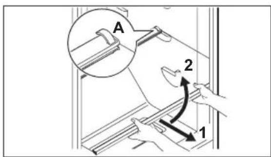
Glass Shell
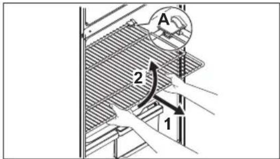
Wire Shelf

CAUTION!
When reinstalling the shelf, ensure the shelf clip is attached to the liner and holds it in place.

CAUTION!
Do not clean glass shelves or covers with warm water when they are cold. Shelves and covers may break if exposed to sudden temperature changes or impact, such as bumping. Tempered glass is designed to shatter into many small, pebble-size pieces. This is normal. Glass shelves and covers are heavy. Use both hands when removing them to avoid dropping.

NOTE
To avoid personal injury or property damage, handle tempered glass shelves carefully. Shelves may break suddenly if nicked, scratched, or exposed to sudden temperature change.
Deli Drawer (some models)

IMPORTANT
Using the deli drawer to store fruits and vegetables may result in frozen produce. The deli drawer is designed to stay colder than the crisper drawers and should only be used to store lucheon meets, spreads, cheeses, and other deli items. Store vegetables and/or fruit in the crisper drawers.

NOTE
Be sure to support the glass when removing the drawer.
Store deli meats or spreads in the half- or full-width sliding deli drawer found in the middle section of your appliance.
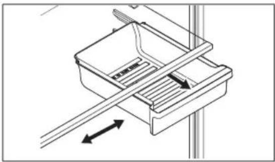
natural_image
Technical line drawing of a mechanical device with internal components and directional arrows (no text or symbols)Half-width sliding deli drawer
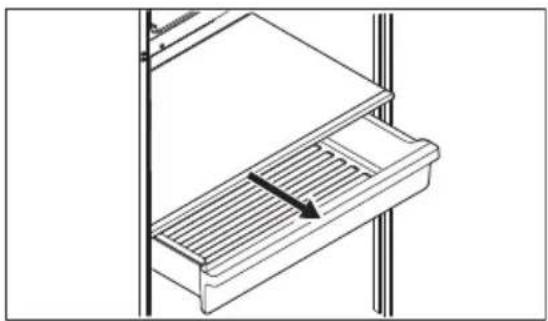
natural_image
Technical line drawing of a mechanical component with a slatted base and an arrow indicating direction (no text or symbols)Full-width sliding deli drawer
Crisper Humidity Control (some models)
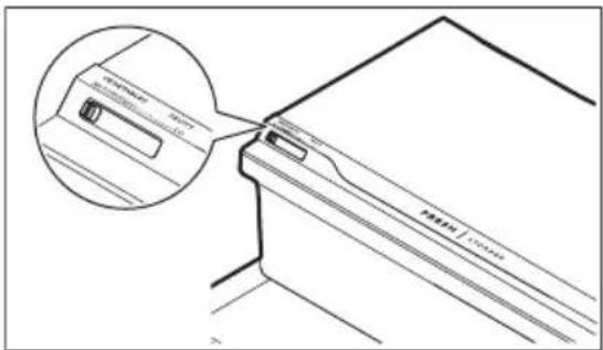
The crisper humidity control, present on the crisper drawers of some models, allows you to adjust the humidity within the crisper. This can extend the life of fresh vegetables that keep best in high humidity.
natural_image
Technical line drawing of a mechanical component with an inset magnified view showing a slot (no text or symbols)
IMPORTANT
Store vegetables and/or fruit in the crisper drawers.

NOTE
Leafy vegetables keep best when stored with the humidity control set on high humidity, or in a drawer without a humidity control. This keeps incoming air to a minimum and maintains maximum moisture content. Store non-leafy vegetables and fruits still in their skins at the low humidity setting.
Auto-humidity control (some models)
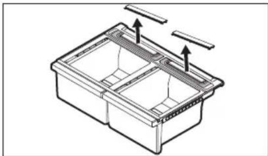
Some crispers have an auto-humidity control at the rear of each crisper under the humidity control cover.
To remove the auto humidity control for cleaning:
- Reach to the back of the humidity control cover.
- Pull up on the cover.
- Pull the cover toward the back of the cabinet and remove.
- Clean the humidity control with hot soapy water.
- Replace the clean humidity control cover by reversing the steps above. Repeat for both crispers.
natural_image
Technical line drawing of a rectangular storage unit with internal compartments and mounting brackets (no text or symbols)
NOTE
We do not recommend replacing the auto-humidity membrane unless it becomes damaged or ruined. If the membrane becomes soiled, it can be washed with soap and water. Ensure the membrane is dry before replacing it in the cover and back in the appliance.
Understanding the sounds you may hear
Your new, high-efficiency appliance may introduce unfamiliar sounds. These sounds normally indicate your appliance is operating correctly. Some surfaces on floors, walls, and kitchen cabinets may make these sounds more noticeable.

NOTE
Energy efficient foam in your appliance is not a sound insulator.
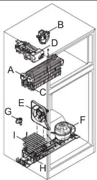
Following is a list of major components in your appliance and the sounds they can cause:
A. Evaporator. Refrigerant through the evaporator may create a boiling or gurgling sound.
B. Evaporator fan. You may hear air being forced through the refrigerator by the evaporator fan.
C. Defrost heater. During defrost cycles, water dripping onto the defrost heater may cause a hissing or sizzling sound. After defrosting, a popping sound may occur.
D. Automatic Ice maker. When ice has been produced, you will hear ice cubes falling into the ice bin.
E. Condenser fan. You may hear air being forced through the condenser.
F. Compressor. Modern, high-efficiency compressors run much faster than previous models. The compressor may have a noticeable hum or pulsating sound during operation.
G. If your appliance is equipped with an automatic ice maker, you will hear a buzzing sound as the water valve opens to fill the ice maker during each cycle.
H. Drain pan (not removable). You may hear water dripping into the drain pan during the defrost cycle.
I. Condenser. May create minimal sounds from forced air.

IMPORTANT
Ice maker models only: If the ice maker is not connected to the household water supply, you may hear a loud chattering noise. Turn off the ice maker by pressing the green On/Off power switch (green LED light will turn off) until you install the water supply line.

NOTE
During automatic defrost cycle, a red glow in the back wall vents of your freezer compartment is normal.
PureAir™ RAF-1 Air Filter
Keep your refrigerator fresh with our PureAir™ RAF-1 air filter's active carbon technology that absorbs and captures undesirable odors more effectively than baking soda. To ensure optimal filtering of refrigerator odors, change the filter every 6 months.
The air filter is located in the top center of the fresh food compartment.
To order replacement filters, please visit our online store at Frigidaire.com or call toll-free at 1-866-831-2306. Here are the product numbers to request when ordering:
PureAir™ RAF-1 Air Filter FRGPAAF1
For models that are air filter ready you will need to purchase a starter kit (TMFRGPAAF1KIT) at
Frigidaire.com.
The kit includes:
• 1 Filter Housing
• 1 Air filter (FRGPAAF1)

NOTE
We recommend you always use genuine Conservator replacement filters only.
Replacing the Air Filter
Some features of the filter housing may vary.
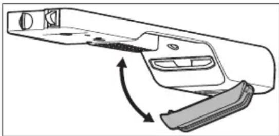
- Unpack the new filter and snap it into the filter housing. The open face (black carbon media) of the filter should be installed facing outward in the cover.
- Place the air filter housing in the refrigerator by snapping it into the back section of the control housing as shown.
natural_image
Diagram of a car door handle with arrows indicating movement or force (no text or symbols)Air filter ready starter kit

IMPORTANT
For optimal performance, change the filter every 6 months.
Protecting your investment
Keeping your appliance clean maintains its appearance and prevents odor build-up. Wipe up any spills immediately and clean the freezer and fresh food compartments at least twice a year. When cleaning, take the following precautions:
- Never use chloride or cleaners with bleach to clean stainless steel.
- Do not wash any removable parts in a dishwasher.
• Always unplug the electrical power cord from the wall outlet before cleaning. - Do not remove the serial plate. Removal of your serial plate voids your warranty.
- Remove adhesive labels by hand. Do not use razor blades or other sharp instruments which can scratch the appliance surface.
Do not use abrasive cleaners such as window sprays, scouring cleansers, brushes, flammable fluids, cleaning waxes, concentrated detergents, bleaches or cleansers containing petroleum products on plastic parts, interior doors, gaskets or cabinet liners. Do not use paper towels, metallic scouring pads, or other abrasive cleaning materials or strong alkaline solutions.
Refer to the guide below for more details on caring and cleaning specific areas of your appliance.

NOTE
If you set your temperature controls to turn off cooling, power to lights and other electrical components will continue until you unplug the power cord from the wall outlet.

CAUTION!
Pull the appliance straight out to move it. Shifting it from side to side may damage flooring. Be careful not to move the appliance beyond the plumbing connections.

IMPORTANT
If you store or move your appliance in freezing temperatures, be sure to completely drain the water supply system. Failure to do so could result in water leaks when the appliance is put back into service. Contact a service representative to perform this operation.
Care & Cleaning Tips
| Part What to use Tips and precautions | ||
| Interior and door liners | ·Soap and water·Baking soda and water | Use two tablespoons of baking soda in one quart of warm water. Be sure to wring excess water out of sponge or cloth before cleaning around controls, light bulb or any electrical part. |
| Door gaskets Soap and water Wipe gaskets with a clean soft | cloth. | |
| Drawers and bins Soap and water Use a soft cloth to clean drawer | runners and tracks. | |
| Glass shelves | ·Soap and water·Glass cleaner·Mild liquid sprays | Allow glass to warm to room temperature before immersing in warm water. |
| Toe grille | ·Soap and water·Mild liquid sprays·Vacuum attachment | Vacuum dust from front of toe grille. Remove toe grille (refer to Installation). Vacuum backside, wipe with sudsy cloth or sponge. Rinse and dry. |
Part What to use Tips and precautions
| Exterior and handles | Soap and waterNon abrasive glass cleaner | Do not use commercial household cleaners containing ammonia, bleach or alcohol to clean handles. Use a soft cloth to clean smooth handles. Do not use a dry cloth to clean smooth doors. |
| Exterior and handles (Stainless steel models only) | Soap and waterStainless steel cleaners | Never use chloride or cleaners with bleach to clean stainless steel. Clean stainless steel front and handles with non-abrasive soapy water and a dishcloth.Rinse with clean water and a soft cloth. Use a non-abrasive stainless steel cleaner. These cleaners can be purchased at most home improvement or major department stores. Always follow manufacturer's instructions. Do not use household cleaners containing ammonia or bleach.Always clean, wipe and dry with the grain to prevent scratching.Wash the rest of the cabinet with warm water and mild liquid detergent. Rinse well, and wipe dry with a clean soft cloth. |
| Replacing LED bulbs | 1. Unplug refrigerator.Wear gloves.Remove light cover.Replace old bulb.Plug in the appliance. |  CAUTION!Wear gloves when replacing LED bulbs to avoid getting cut.Use only a 5-watt or less AC LED light bulb. CAUTION!Wear gloves when replacing LED bulbs to avoid getting cut.Use only a 5-watt or less AC LED light bulb. |
| Air Filter Order Air Filter Housing KitTMFRGPAAF1KIT, which includes a Pure-AirtM RAF-1 air filter at Frigidaire.com. | Our PureAirTM RAF-1 air filter's active carbon technology absorbs and captures undesirable odors more effectively than baking soda. | |
CAUTION!
Let us help you troubleshoot your concern! This section will help you with common issues. If you need us, visit our website, chat with an agent, or call us. We may be able to help you avoid a service visit. If you do need service, we can get that started for you!
Visit Frigidaire.com or call toll-free 1-866-831-2306.
Common occurrences
| Refrigerator does not run. | ·Ensure the plug is tightly pushed into an electrical outlet.·Check/replace the fuse with a 15amp time-delay fuse. Reset the circuit breaker.·The refrigerator control is turned to OFF.·Refrigerator may be in defrost cycle. Wait 20 minutes and check again. |
| Freezer temperature is colder than preferred. Refrigerator temperature is satisfactory. | Set the auxiliary freezer control to a warmer setting until the freezer temperature is satisfactory. Allow 24 hours for the temperature to stabilize. |
| Refrigerator temperature is too cold. Freezer temperature is satisfactory. | Set the refrigerator control to a warmer setting. Allow 24 hours for the temperature to stabilize. Then check the freezer temperature and adjust as needed. |
| Freezer temperature is warmer than preferred. Refrigerator temperature is satisfactory. | Set the auxiliary freezer control to a colder setting until the freezer temperature is satisfactory. Allow 24 hours for the temperature to stabilize. |
| Refrigerator temperature is too warm. Freezer temperature is satisfactory. | Set the refrigerator control to a colder setting. Allow 24 hours for temperature to stabilize. Then check refrigerator temperature and adjust as needed. |
| Refrigerator is noisy or vibrates. | ·The cabinet is not level.·Floor is weak.·Refer to Normal Operating Sounds. |
| Odors in the refrigerator. | ·The interior needs to be cleaned.·Foods that produce odors should be covered or wrapped. |
| Cabinet light is not working. | ·Replace with only a 5Watt or less AC LED light bulb.·Ensure the plug is tightly pushed into an electrical outlet.·The light switch may be stuck. Push in the light switch, located on the refrigerator side wall, to release. |
| Automatic ice maker is not working (some models) | ·Ensure the ice maker is on (green light).·The ice maker should produce 2 to 2.5 pounds of ice in a 24 hour period.·Ensure the water supply is turned on.·The water pressure may be too low.·The freezer may not be cold enough. |
Ice Maker is not making enough ice (some models) Set the freezer control to a colder setting to improve the performance of the ice maker. Allow 24 hours for the temperature to stabilize.
Mullion is warm Mullion may be warm to the touch for the first 24 hours of operation. This is normal.
Your appliance is covered by a one year limited warranty. For one year from your date of delivery, Electrolux will pay all costs for repairing or replacing any parts of this appliance that prove to be defective in materials or workmanship when such appliance is installed, used and maintained in accordance with the provided instructions.
Exclusions
This warranty does not cover the following:
- Products with original serial numbers that have been removed, altered or cannot be readily determined.
- Product that has been transferred from its original owner to another party or removed outside the USA or Canada.
- Rust on the interior or exterior of the unit.
- Products purchased "as-is" are not covered by this warranty.
- Food loss due to any refrigerator or freezer failures.
- Products used in a commercial setting.
- Service calls which do not involve malfunction or defects in materials or workmanship, or for appliances not in ordinary household use or used other than in accordance with the provided instructions.
- Service calls to correct the installation of your appliance or to instruct you how to use your appliance.
- Expenses for making the appliance accessible for servicing, such as removal of trim, cupboards, shelves, etc., which are not a part of the appliance when it is shipped from the factory.
- Service calls to repair or replace appliance light bulbs, air filters, water filters, other consumables, or knobs, handles, or other cosmetic parts.
- Surcharges including, but not limited to, any after hour, weekend, or holiday service calls, tolls, ferry trip charges, or mileage expense for service calls to remote areas, including the state of Alaska.
- Damages to the finish of appliance or home incurred during transportation or installation, including but not limited to floors, cabinets, walls, etc.
- Damages caused by: services performed by unauthorized service companies; use of parts other than genuine Electrolux parts or parts obtained from persons other than authorized service companies; or external causes such as abuse, misuse, inadequate power supply, accidents, fires, or acts of God.
DISCLAIMER OF IMPLIED WARRANTIES; LIMITATION OF REMEDIES
CUSTOMER'S SOLE AND EXCLUSIVE REMEDY UNDER THIS LIMITED WARRANTY SHALL BE PRODUCT REPAIR OR REPLACEMENT AS PROVIDED HEREIN. CLAIMS BASED ON IMPLIED WARRANTIES, INCLUDING WARRANTIES OF MERCHANTABILITY OR FITNESS FOR A PARTICULAR PURPOSE, ARE LIMITED TO ONE YEAR OR THE SHORTEST PERIOD ALLOWED BY LAW, BUT NOT LESS THAN ONE YEAR. ELECTROLUX SHALL NOT BE LIABLE FOR CONSEQUENTIAL OR INCIDENTAL DAMAGES SUCH AS PROPERTY DAMAGE AND INCIDENTAL EXPENSES RESULTING FROM ANY BREACH OF THIS WRITTEN LIMITED WARRANTY OR ANY IMPLIED WARRANTY. SOME STATES AND PROVINCES DO NOT ALLOW THE EXCLUSION OR LIMITATION OF INCIDENTAL OR CONSEQUENTIAL DAMAGES, OR LIMITATIONS ON THE DURATION OF IMPLIED WARRANTIES, SO THESE LIMITATIONS OR EXCLUSIONS MAY NOT APPLY TO YOU. THIS WRITTEN WARRANTY GIVES YOU SPECIFIC LEGAL RIGHTS. YOU MAY ALSO HAVE OTHER RIGHTS THAT VARY FROM STATE TO STATE.
If You Need Service
Keep your receipt, delivery slip, or some other appropriate payment record to establish the warranty period should service be required. If service is performed, it is in your best interest to obtain and keep all receipts. Service under this warranty must be obtained by contacting Electrolux at the addresses or phone numbers below.
This warranty only applies in the USA and Canada. In the USA, your appliance is warranted by Electrolux Major Appliances North America, a division of Electrolux Home Products, Inc. In Canada, your appliance is warranted by Electrolux Canada Corp. Electrolux authorizes no person to change or add to any obligations under this warranty. Obligations for service and parts under this warranty must be performed by Electrolux or an authorized service company. Product features or specifications as described or illustrated are subject to change without notice.
Service Number
1-866-831-2306
The Crosley Group, Inc.
Emerald Isle, NC 28594
Conservator
www.conservatorappliances.com
For Extended Warranty or other Information contact:
Crosley Extended Warranty
1-800-356-5268
St. Louis, MO 63126
natural_image
Line drawing of a cabinet interior with a directional arrow pointing to the front panel (no text or symbols)natural_image
Line drawing of a refrigerator with two open compartments (no text or symbols)
IMPORTANTE
natural_image
Diagram showing a plug socket connected to a terminal block, with no text or symbols present.
IMPORTANTE
natural_image
Diagram of a mechanical device with a rotating knob and directional arrow (no text or symbols)
NOTA
natural_image
Line drawing of a refrigerator interior showing front, side, and interior compartments with no text or symbolsnatural_image
Technical diagram showing mechanical assembly with two circular insets highlighting components (no text or symbols)natural_image
Technical line drawing of a mechanical component with no visible text or symbolsA. Pasador de bisagra
B. Tornillos
C. Bisagra central
natural_image
Pure technical line drawing of a mechanical or architectural component without any text, numbers, or symbolsnatural_image
Mechanical assembly diagram showing a disassembly step with tool and component views (no text or labels)natural_image
Diagram of a mechanical assembly with a tool and component, no text or symbols presentnatural_image
Diagram showing a wrench interacting with a mechanical component, highlighting a bolt detail (no text or symbols present)natural_image
Technical line drawing of a refrigerator with an inset showing a mechanical clamp mechanism (no text or symbols)Bisagra tipo A
natural_image
Technical illustration of a refrigerator with internal components and assembly steps (no text or symbols)Bisagra tipo B
natural_image
Technical diagram of a mechanical bracket with an inset showing a 3D model (no text or symbols present)12
natural_image
Simple line drawing of a mechanical component with no text or symbols
PRECAUCIÓN!
natural_image
Technical diagrams showing mechanical assembly with arrows indicating direction (no text or symbols)Manija de plástico
natural_image
Pure diagram of curved arrows and lines without any text, numbers, or symbolsnatural_image
Pure mechanical diagram showing a lever mechanism with a circular component and an arrow indicating direction (no text or symbols)natural_image
Pure diagram of a vertical pipe or duct with directional arrows indicating flow or movement, no text or symbols present.natural_image
Diagram showing a mechanical component with motion arrows indicating direction (no text or symbols)natural_image
Pure mechanical diagram showing a lever mechanism with a circular component and an arrow, no text or symbols present.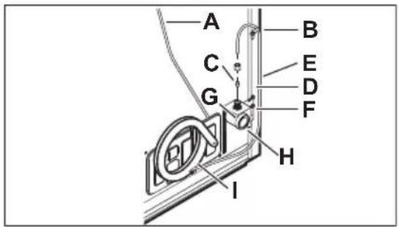
Todos los modelos

NOTA
natural_image
Technical diagram of a mechanical assembly with arrows indicating force or movement (no text or symbols present)natural_image
Technical line drawing of a mechanical device with internal components and directional arrows (no text or symbols)natural_image
Technical line drawing of a mechanical device with a grater and an arrow indicating direction (no text or symbols)natural_image
Technical line drawing of a mechanical component with an inset magnified view (no text or symbols)
IMPORTANTE
natural_image
Isometric line drawing of a rectangular container with internal compartments and two side slabs (no text or symbols)
NOTA

IMPORTANTE
natural_image
Technical line drawing of a mechanical component with directional arrows indicating motion (no text or symbols)The Crosley Group, Inc.
Emerald Isle, NC 28.594
Conservator
www.conservatorappliances.com
Crosley Extended Warranty
1-800-356-5268
St. Louis, MISURI 63126
natural_image
Line drawing of a cabinet interior with a directional arrow pointing to the front panel (no text or symbols)natural_image
Line drawing of a refrigerator with two open compartments, one closed and one fully open (no text or symbols)
IMPORTANT
natural_image
Diagram showing a plug socket connected to a cable, with no text or symbols present
IMPORTANT
natural_image
Diagram of a helicopter's head and fuselage with directional arrows indicating rotation (no text or labels)
REMARQUE
natural_image
Line drawing of a refrigerator interior showing front, back, and side views with no text or symbolsRetrait de la porte

ATTENTION!
natural_image
Technical diagram showing mechanical assembly with two circular insets highlighting components (no text or symbols present)natural_image
Pure technical line drawing of a mechanical component with no text, numbers, or symbolsnatural_image
Pure technical line drawing of a mechanical or architectural component without any text, numbers, or symbolsnatural_image
Mechanical assembly diagram showing a disassembly step with magnified views of internal components (no text or symbols)natural_image
Diagram showing a tool interacting with a device, with an inset illustrating the motion of the tool (no text or symbols present)natural_image
Diagram showing a mechanical device with a tool interacting with a component, enclosed in a circular arrow (no text or symbols present)natural_image
Technical line drawing of a refrigerator with an inset showing a mechanical clamp or bracket assembly (no text or symbols present)Charnière de type A
natural_image
Technical illustration of a refrigerator with internal components and assembly steps (no text or symbols)Charnière de type B
natural_image
Technical line drawing of a mechanical bracket with an inset showing a close-up of a component (no text or symbols present)natural_image
Technical line drawing of a mechanical component with a base and mounting base (no text or symbols)
ATTENTION!
natural_image
Technical diagram showing two mechanical assembly states with arrows indicating movement or force directions (no text or symbols present)natural_image
Pure diagram of curved arrows inside a 3D rectangular frame, no text or symbols presentnatural_image
Pure diagram of a curved pipe or duct with directional arrows indicating flow or movement, no text or symbols present.natural_image
Simple line drawing of a mechanical lever system with a circular head and fulcrum, showing no text or symbols.natural_image
Diagram showing a mechanical component with two rotating parts and directional arrows indicating motion (no text or symbols)natural_image
Pure mechanical diagram showing a lever and pivot point with no text or symbols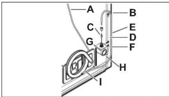
Tous les modèles

REMARQUE
natural_image
Technical diagram of a mechanical assembly with arrows indicating force or movement (no text or symbols present)natural_image
Technical line drawing of a mechanical device with directional arrows indicating movement or force (no text or symbols)natural_image
Technical line drawing of a mechanical component with a slatted base and an arrow indicating direction (no text or symbols)
IMPORTANT
natural_image
Technical line drawing of a rectangular storage unit with internal compartments and mounting brackets (no text or symbols)
REMARQUE

IMPORTANT
natural_image
Diagram of a car door handle with internal components and directional arrows indicating movement (no text or symbols)Emerald Isle, NC 28594
Conservator
www.conservatorappliances.com

- Welcome to our family
- Keep a record for quick reference
- WARNING!
- Safety Definitions
- DANGER
- CAUTION!
- IMPORTANT
- Child Safety
- IMPORTANT SAFETY INSTRUCTIONS
- Before you throw away your old refrigerator/freezer:
- CFC/HCFC Disposal
- Proper Disposal of your Refrigerator or Freezer
- Risk of child entrapment
- Electrical information
- Installation Checklist
- Doors
- Leveling
- Electrical Power
- Ice Maker
- Final Checks
- Tools necessary
- Cleaning the appliance
- Moving the appliance
- Location
- NOTE
- Cabinet leveling and door alignment
- Setting the anti-tip brackets
- Mullion
- Door Removal
- Door reversal
- Metal handle
- Plastic handle
- Door handle reversal
- Before Installing The Water Supply Line
- You will need
- Installing the water supply line
- Automatic ice maker
- Turning ice maker on
- Turning ice maker off
- Ice production
- Cool down period
- Freezer control
- Refrigerator Controls
- Door Storage
- Door Bin
- Shelf adjustment
- Deli Drawer (some models)
- Crisper Humidity Control (some models)
- Auto-humidity control (some models)
- Understanding the sounds you may hear
- PureAir™ RAF-1 Air Filter
- Replacing the Air Filter
- Protecting your investment
- Exclusions
- DISCLAIMER OF IMPLIED WARRANTIES; LIMITATION OF REMEDIES
- If You Need Service
- Service Number
- IMPORTANTE
- NOTA
- 12
- PRECAUCIÓN!
- Manija de plástico
- REMARQUE
- Retrait de la porte
- ATTENTION!
Brand : Crosley
Model : CFUE2021AW
Category : Freezer