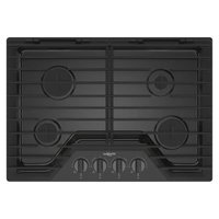
WCGK5030PV - Cooker WHIRLPOOL - Free user manual and instructions
Find the device manual for free WCGK5030PV WHIRLPOOL in PDF.


User questions about WCGK5030PV WHIRLPOOL
0 question about this device. Answer the ones you know or ask your own.
Ask a new question about this device
Download the instructions for your Cooker in PDF format for free! Find your manual WCGK5030PV - WHIRLPOOL and take your electronic device back in hand. On this page are published all the documents necessary for the use of your device. WCGK5030PV by WHIRLPOOL.
USER MANUAL WCGK5030PV WHIRLPOOL
GAS BUILT-IN COOKTOP OWNER'S MANUAL MANUEL DU PROPRIÉTAIRE DE LA TABLE DE CUISSON À GAZ ENCASTRÉE
Table of Contents/Table des matières
COOKTOP SAFETY 2
Cooktop Safety 2
COOKTOP MAINTENANCE AND CARE 4
General Cleaning....4
INSTALLATION INSTRUCTIONS 5
REQUIREMENTS......5
Tools and Parts 5
Location Requirements 5
Electrical Requirements 7
Gas Supply Requirements 7
INSTALLATION 8
Install Cooktop 8
Make Gas Connection 9
Complete Installation 11
GAS CONVERSIONS.... 11
Convert from Natural Gas to Propane Gas 12
Convert from Propane Gas to Natural Gas 14
Lighting the Electronic Igniters 16
Low Flame Height Adjustment 16
Complete Burner Adjustment 17
Moving the Cooktop 17
SÉCURITÉ DE LA TABLE DE CUISSON.... 18
Installer: Leave installation instructions with the homeowner.
Homeowner: Keep installation instructions for future reference.
IMPORTANT :
Your safety and the safety of others are very important.
We have provided many important safety messages in this manual and on your appliance. Always read and obey all safety messages.

This is the safety alert symbol.
This symbol alerts you to potential hazards that can kill or hurt you and others.
All safety messages will follow the safety alert symbol and either the word "DANGER" or "WARNING." These words mean:
DANGER
WARNING
You can be killed or seriously injured if you don't immediately follow instructions.
You can be killed or seriously injured if you don't follow instructions.
All safety messages will tell you what the potential hazard is, tell you how to reduce the chance of injury, and tell you what can happen if the instructions are not followed.
WARNING: If the information in these instructions is not followed exactly, a fire or explosion may result causing property damage, personal injury or death.
- Do not store gasoline or other flammable vapors and liquids in the vicinity of this or other appliance.
-
WHAT TO DO IF YOU SMELL GAS
-
Do not try to light any appliance.
- Do not touch any electrical switch.
- Do not use any phone in your building.
- Immediately call your gas supplier from a neighbor's phone. Follow the gas suppliers instructions.
- If you cannot reach your gas supplier, call the fire department.
- Installation and service must be performed by a qualified installer, service agency or the gas supplier.
WARNING: Gas leaks cannot always be detected by smell.
Gas suppliers recommend that you use a gas detector approved by UL or CSA.
For more information, contact your gas supplier.
If a gas leak is detected, follow the "What to do if you smell gas" instructions.

WARNING:
Never Operate the Top Surface Cooking Section of this Appliance Unattended
- Failure to follow this warning statement could result in fire, explosion, or burn hazard that could cause property damage, personal injury, or death.
- If a fire should occur, keep away from the appliance and immediately call your fire department.
DO NOT ATTEMPT TO EXTINGUISH AN OIL/GREASE FIRE WITH WATER.
IMPORTANT: Do not install a ventilation system that blows air downward toward this gas cooking appliance. This type of ventilation system may cause ignition and combustion problems with this gas cooking appliance resulting in personal injury or unintended operation.
In the State of Massachusetts, the following installation instructions apply:
■ Installation and repairs must be performed by a qualified or licensed contractor, plumber, or gas fitter qualified or licensed by the State of Massachusetts.
■ Acceptable Shut-off Devices: Gas Cocks and Ball Valves installed for use shall be listed.
■ A flexible gas connector, when used, must not exceed 4 feet (121.9 cm).
IMPORTANT SAFETY INSTRUCTIONS
WARNING: To reduce the risk of fire, electrical shock, injury to persons, or damage when using the cooktop, follow basic precautions, including the following:

WARNING
NEVER use this appliance as a space heater to heat or warm the room. Doing so may result in carbon monoxide poisoning and overheating of the cooktop.
■ WARNING: Danger of fire: Do not store items on the cooking surfaces. Never leave anything on the surface when unattended and not in use. Never place flammable plastic items on or near the surface.
■ CAUTION: Do not store items of interest to children in cabinets above the cooktop – children climbing on the cooktop to reach items could be seriously injured.
■ Do Not Leave Children Alone - Children should not be left alone or unattended in area where appliance is in use. They should never be allowed to sit or stand on any part of the appliance.
■ Wear Proper Apparel – Loose-fitting or hanging garments should never be worn while using the appliance.
■ User Servicing – Do not repair or replace any part of the appliance unless specifically recommended in the manual. All other servicing should be referred to a qualified technician.
■ Do Not Use Water on Grease Fires – Smother fire or flame or use dry chemical or foam-type extinguisher.
■ Use Only Dry Potholders – Moist or damp potholders on hot surfaces may result in burns from steam. Do not let potholder touch hot surface units. Do not use a towel or other bulky cloth.
■ Never Leave Surface Units Unattended at Higher Heat Settings - Cooking oils and animal fats are flammable, boilover may cause smoking, and greasy spillovers may ignite.
■ Glazed Cooking Utensils – Only certain types of glass, glass/ceramic, ceramic, earthenware, or other glazed utensils are suitable for range-top service without breaking due to the sudden change in temperature.
■ Utensil Handles Should Be Turned Inward and Not Extend Over Adjacent Surface Units – To reduce the risk of burns, ignition of flammable materials, and spillage due to unintentional contact with the utensil, the handle of a utensil should be positioned so that it is turned inward, and does not extend over adjacent surface units.
■ Do not use replacement parts that have not been recommended by the manufacturer (e.g. parts made at home using a 3D printer).
- Clean Cooktop With Caution – If a wet sponge or cloth is used to wipe spills on a hot cooking area, be careful to avoid steam burn. Some cleaners can produce noxious fumes if applied to a hot surface.
■ Do Not Heat Unopened Food Containers – Build-up of pressure may cause container to burst and result in injury.
■ Proper Installation - The appliance, when installed, must be electrically grounded in accordance with local codes, or in the absence of local codes, with the National Electrical Code, ANSI/NFPA 70 or the Canadian Electrical Code, CSA C22.1. In Canada, the appliance must be electrically grounded in accordance with Canadian Electrical Code. Be sure your appliance is properly installed and grounded by a qualified technician.
This cooktop is equipped with a three-prong grounding plug for your protection against shock hazard and should be plugged directly into a properly grounded receptacle. Do not cut or remove the grounding prong from this plug.
■ Disconnect the electrical supply before servicing the cooktop.
■ Injuries may result from the misuse of the cooktop such as stepping, leaning, or sitting on the top surface.
■ Maintenance – Keep cooktop area clear and free from combustible materials, gasoline, and other flammable vapors and liquids.
■ Top burner flame size should be adjusted so it does no extend beyond the edge of the cooking utensil. This instruction is based on safety considerations.
For units with ventilating hood -
■ Clean Ventilating Hoods Frequently – Grease should not be allowed to accumulate on hood or filter.
■ When flaming foods under the hood, turn the fan on.
For smart enabled ranges and ovens
■ Remote operation – This appliance is configurable to allow remote operation at any time. Do not store any flammable materials or temperature sensitive items inside, on top or near surface units of the appliance.
SAVE THESE INSTRUCTIONS
COOKTOP MAINTENANCE AND CARE
General Cleaning
IMPORTANT: Before cleaning, make sure all controls are off and the cooktop is cool. Always follow label instructions on cleaning products.
Soap, water, and a soft cloth or sponge are suggested first, unless otherwise noted.
CERAMIC GLASS (on some models)
Cleaning Method:
To avoid damaging the cooktop, do not use steel wool, abrasive powder cleansers, chlorine bleach, rust remover, or ammonia.
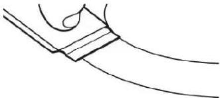
- Remove food/residue with the Cooktop Scraper.
natural_image
Simple line drawing of a hand holding a curved object with a rectangular block (no text or symbols)■ For best results, use the Cooktop Scraper while the cooktop is still warm but not hot to the touch. It is recommended to wear an oven mitt while scraping the warm cooktop.
- Hold the Cooktop Scraper at approximately a 45° angle against the glass surface and scrape the residue. It will necessary to apply pressure in order to remove the residue.
Allow the cooktop to cool down completely before proceeding to Step 2.
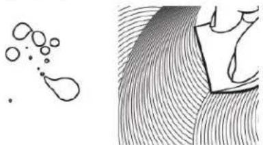
- Apply a few dime-sized drops of affresCooktop Cleaner to the affected areas.
natural_image
Abstract line drawing of a teardrop shape and a wavy surface with layered lines (no text or symbols)■ Rub affresh® Cooktop Cleaner onto the cooktop surface with the blue Cooktop Cleaning Pad. Some pressure is needed to remove stubborn stains.
■ Allow the cleaner to dry to a white haze before proceeding to Step 3.
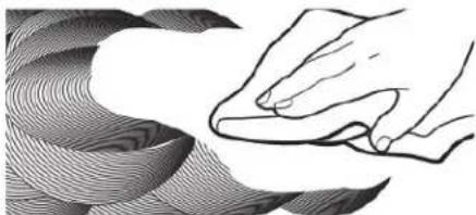
- Polish with a clean, dry cloth or a clean, dry paper towel.
natural_image
Illustration of a hand pressing down on a curved surface with wavy patterns (no text or symbols)■ Repeat steps 1 through 3 as necessary for stubborn or burned-on stains.
The Complete Cooktop Cleaner Kit is available for order including the following:
■ Cooktop Scraper
■ Affresh® Cooktop Cleaner
■ Blue Cooktop Cleaning Pads
Refer to the Quick Start Guide for contact information.
EXTERIOR PORCELAIN ENAMEL SURFACES (on some models)
Food spills containing acids, such as vinegar and tomato, should be cleaned as soon as the cooktop, grates and caps are cool. These spills may affect the finish.
To avoid chipping, do not bang grates and caps against each other or hard surfaces such as cast iron cookware.
Do not reassemble caps on burners while wet.
Do not clean in the Self-Cleaning cycle.
Do not clean in dishwasher.
bCleaning Method:
■ Nonabrasive plastic scrubbing pad and mildly abrasive cleanser:
Clean as soon as cooktop, grates and caps are cool.
■ Gas Grate and Drip Pan Cleaner (not included):
Refer to the Quick Start Guide for contact information.
STAINLESS STEEL (on some models)
To avoid damage to stainless steel surfaces, do not use soap-filled scouring pads, abrasive cleaners, Cooktop Cleaner, steel wool pads, gritty wash cloths, or abrasive paper towels.
Rub in direction of grain to avoid damaging.
Cleaning Method:
■ All-purpose cleaner:
Rinse with clean water and dry with soft, lint-free cloth.
■ Affresh® Stainless Steel Cleaner (not included):
Refer to the Quick Start Guide for contact information.
BLACK STAINLESS STEEL (on some models)
To avoid damage to black stainless steel surfaces, do not use soap-filled scouring pads, abrasive or harsh cleaners, any cleaning product containing chlorine bleach, steel wool pads, gritty washcloths, or paper towels.
Cleaning Method:
■ Rinse with clean water and dry with soft, lint-free cloth.
■ Warm, soapy water - a mild detergent
COOKTOP CONTROLS
To avoid damage to the cooktop controls, do not use steel wool, abrasive cleansers, or oven cleaner.
To avoid damage, do not soak knobs.
When replacing knobs, make sure knobs are in the Off position.
Do not remove seals under knobs.
†affresh® is a registered trademark of Whirlpool, U.S.A.
Cleaning Method:
■ Soap and water:
Pull knobs straight away from control panel to remove.
■ Dishwasher Safe
CONTROL PANEL
To avoid damage to the control panel, do not use abrasive cleaners, steel wool pads, gritty washcloths or abrasive paper towels.
Cleaning Method:
■ Glass cleaner and soft cloth or sponge: Apply glass cleaner soft cloth or sponge, not directly on panel.
■ Affresh ^® Kitchen and Appliance Cleaner (not included): Order Part Number W10355010
PORCELAIN-COATED GRATES AND CAPS
Food spills containing acids, such as vinegar and tomato, should be cleaned as soon as the cooktop, grates and caps are cool.
These spills may affect the finish.
To avoid chipping, do not bang grates and caps against each other or hard surfaces such as cast iron cookware.
Do not reassemble caps on burners while wet.
Cleaning Method:
■ Nonabrasive plastic scrubbing pad and mildly abrasive cleanser:
Clean as soon as cooktop, grates and caps are cool.
■ Dishwasher (grates only, not caps):
Use the most aggressive cycle.
■ Gas Grate and Drip Pan Cleaner Part Number 31617 (not included):
Refer to the Quick Start Guide for contact information.
SURFACE BURNERS
Sealed Burner models
See the "Sealed Surface Burners" section in the online Control Guide.
SIMMER PLATE (on some models)
Do not clean in dishwasher.
Cleaning Method:
■ Liquid detergent and water:
Wipe with damp cloth or sponge then rinse with clean water and wipe dry.
■ Mild-abrasive cleanser:
Rub in the direction of the grain lines with a damp cloth.
GRIDDLE (on some models)
To avoid damaging the nonstick surface, do not clean the griddle with abrasive cleaners.
Cleaning Method:
■ Use soap and water or mild detergent.
INSTALLATION INSTRUCTIONS REQUIREMENTS
Tools and Parts
Tools Needed
■ Tape measure
■ Flat-blade screwdriver
■ Phillips screwdriver
15/16" (24 mm) combination wrench
■ Pipe wrench
■ Wrench or pliers
■ Marker or pencil
■ Pipe-joint compound resistant to Propane gas
■ Noncorrosive leak-detection solution
Parts Supplied
■ Gas pressure regulator
■ Burner grates
■ Burner caps
■ Burner base
■ Clamping brackets (2)
■ Bracket attachment screws (2)
For Propane/Natural Gas Conversions
Tools Needed
■ Flat-blade screwdriver
■ T20 ^® TORX ^®+ screwdriver
■ Adjustable wrench
■ 7.0 mm nut driver
■ Masking tape
■ 7.0 mm wrench
Parts Supplied
■ Propane orifice package
■ Conversion instructions
■ Conversion label
Parts needed
Check local codes and consult gas supplier. Check existing gas supply and electrical supply. See "Electrical Requirements" and "Gas Supply Requirements" sections.
NOTE: Be sure to purchase only Whirlpool factory-certified parts and accessories for your appliance. Your installation may require additional parts. To order, refer to the contact information referenced in your Quick Start Guide.
Location Requirements
IMPORTANT: Observe all governing codes and ordinances. Do not obstruct flow of combustion and ventilation air.
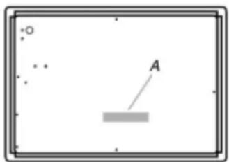
It is the installer's responsibility to comply with installation clearances specified on the model/serial/rating plate. The model/serial/rating plate is located on the underside of the cooktop base.
natural_image
Simple diagram with a rectangular frame, scattered dots, and a labeled point A pointing to a shaded rectangle (no text or symbols beyond the label)A. Model/serial/rating plate
■ The cooktop must be a specified cooktop that is approved to be installed either alone or over an undercounter built-in oven. Check the cooktop base approved installation label for your cooktop model number and approved combinations of cooktops and ovens that can be installed. If you do not find label, your cooktop may not be approved for use over an undercounter built-in oven. Contact your dealer to confirm that your cooktop is approved.
■ Ovens approved for this type of installation will have an approval label located on the top of the oven. If you do not find this label, contact your dealer to confirm that your oven is approved. Refer to oven manufacturer's Installation Instructions for approval for built-in undercounter use and proper cutout dimensions.
■ The cooktop should be installed in a location away from strong draft areas, such as windows, doors and strong heating vents or fans.
■ All openings in the wall or floor where cooktop is to be installed must be sealed.
■ Cabinet opening dimensions that are shown must be used. Given dimensions are minimum clearances.
■ Grounded electrical supply is required. See "Electrical Requirements" section. Proper gas supply connection must be available. See "Gas Supply Requirements" section.
■ The cooktop is designed to hang from the countertop by its side or rear flanges.
■ The gas and electric supply should be located as shown in "Cabinet Dimensions" section so that they are accessible without requiring removal of the cooktop.
■ Provide cutout in right rear corner of cutout enclosure as shown to provide clearance for gas inlet, power supply cord, and to allow the rating label to be visible.
IMPORTANT: To avoid damage, check with your builder or cabinet supplier to make sure that the materials used will not discolor, delaminate or sustain other damage.
Mobile Home - Additional Installation Requirements
The installation of this cooktop must conform to the Manufactured Home Construction and Safety Standard, Title 24 CFR, Part 3280 (formerly the Federal Standard for Mobile Home Construction and Safety, Title 24, HUD Part 280). When such standard is not applicable, use the Standard for Manufactured Home Installations, ANSI A225.1/NFPA 501A or local codes.
In Canada, the installation of this range must conform with the current standards CAN/CSA-Z240.1, latest edition, or with local codes.
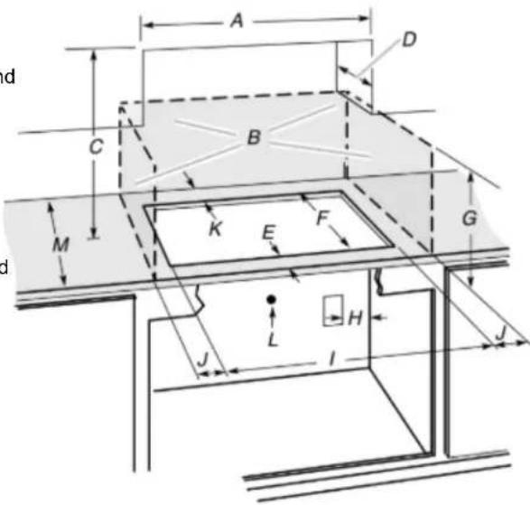
Cabinet Dimensions
IMPORTANT: If installing a range hood or microwave hood combination above the cooktop, follow the range hood or microwave hood combination installation instructions for this dimensional clearances above the cooktop surface.
text_image
d A D C B M K E F G d J L H I JA. 30" (76.2 cm) on 30" models; 36" (91.4 cm) on 36" models
B. Combustible area above countertop (shown by dashed box above)
C. 30" (76.2 cm) minimum clearance between top of cooktop platform and bottom of uncovered wood or metal cabinet (24" [61 cm] minimum clearance if bottom of wood or metal cabinet is covered by not less than 1/4" [6.4 mm] flame retardant millboard covered with not less than No. 28 MSG sheet steel, 0.015" [0.04 mm] stainless steel, or 0.024" [0.06 mm] aluminum or 0.020" [0.05 mm] copper).
D. 13" (33 cm) recommended upper cabinet depth.
E. 3^1/8 " (7.9 cm)
F. 19 12 " (49.5 cm)
G. 18" (45.7 cm) minimum clearance from upper cabinet to countertop within minimum horizontal clearances to cooktop.
H. Grounded outlet: locate within 24" (61 cm) of right rear corner of cutout.
I. 28 7/8" (73.4 cm) on 30" models; 34/16" (87.0 cm) on 36" models
J. For WCGK7530 models, the minimum distance to the left and right side combustible surfaces must be 12/2" (31.9 cm) and the minimum total distance between the left and right side combustible surfaces must be 78" (198.1 cm).
For WCGK7036 and WCGK7536 models, the minimum distance to the left or right side combustible surfaces must be 17/8" (32.7 cm) and the minimum total distance between left and right side combustible surfaces must be 84" (213.4 cm). For all other 30" models, the distance must be 8/2" (21.6 cm) or more on each side. For all other 36" models, the distance must be 87/8" (22.5 cm) or more on each side.
K. 27/8" (7.3 cm) minimum distance to rear combustible surface.
L. Gas line opening - wall: anywhere 5" (12.7 cm) below underside of countertop. Cabinet floor: anywhere within 6" (15.2 cm) of rear wall is recommended.
M. 25 12 " (64.7 cm) minimum countertop depth is required.
NOTE: After making the countertop cutout, some installations may require notching down the base cabinet side walls to clear the cooktop base. To avoid this modification, use a base cabinet with sidewalls wider than the cutout.
If cabinet has a drawer, a 4" (10.2 cm) depth clearance from the countertop to the top of the drawer (or other obstruction) in base cabinet is required. The drawer depth may need to be shortened to avoid interfering with the regulator.
Electrical Requirements
WARNING
Electrical Shock Hazard
Plug into a grounded 3 prong outlet.
Do not remove ground prong.
Do not use an adapter.
Do not use an extension cord.
Failure to follow these instructions can result in death, fire, or electrical shock.
IMPORTANT: The cooktop must be electrically grounded in accordance with local codes and ordinances, or in the absence of local codes, with the National Electrical Code, ANSI/NFPA 70 or Canadian Electrical Code, CSA C22.1.
This cooktop is equipped with an electronic ignition system that will not operate if plugged into an outlet that is not properly polarized.
If codes permit and a separate ground wire is used, it is recommended that a qualified electrical installer determine that the ground path is adequate.
A copy of the above code standards can be obtained from:
National Fire Protection Association
1 Batterymarch Park
Quincy, MA 02169-7471
CSA International
8501 East Pleasant Valley Road
Cleveland, OH 44131-5575
■ A 120 V, 60 Hz, AC only, 15 A, fused electrical circuit is required. A time-delay fuse or circuit breaker is also recommended. It is recommended that a separate circuit serving only this cooktop be provided.
■ Electronic ignition systems operate within wide voltage limits, but proper grounding and polarity are necessary. Check that the outlet provides 120 V power and is correctly grounded.
■ The wiring diagrams are provided with this cooktop. See the "Wiring Diagrams".
Gas Supply Requirements
WARNING

Explosion Hazard
Use a new CSA International approved gas supply line.
Install a shut-off valve.
Securely tighten all gas connections.
If connected to propane, have a qualified person make sure gas pressure does not exceed 14" (36 cm) water column.
Examples of a qualified person include: licensed heating personnel, authorized gas company personnel, and authorized service personnel.
Failure to do so can result in death, explosion, or fire.
Observe all governing codes and ordinances.
IMPORTANT: This installation must conform with all local codes and ordinances. In the absence of local codes, installation must conform with the National Fuel Gas Code, ANSI Z223.1/NFPA 54 or, in Canada, the Natural Gas and Propane Installation Code, CSA B149.1 - latest edition.
IMPORTANT: Leak testing of the cooktop must be conducted according to the manufacturer's instructions.
Type of Gas
Natural Gas:
This cooktop is factory set for use with Natural gas. If converting to Propane gas, see the following “Propane Gas Conversion” section. The model/serial/rating plate located on the underside of the cooktop base has information on the types of gas that can be used. If the types of gas listed do not include the type of gas available, check with the local gas supplier.
Propane Gas Conversion:
Conversion must be done by a qualified service technician.
No attempt shall be made to convert the cooktop from the gas specified on the model/serial/rating plate for use with a different gas without consulting the serving gas supplier. See the Gas Conversion instructions provided in the package containing literature.
Gas Supply Line
■ Provide a gas supply line of 3/4" (19 mm) rigid pipe to the cooktop location. A smaller size pipe on longer runs may re in insufficient gas supply. Pipe-joint compounds that resist th
action of Propane gas must be used. Do not use TEFLON tape. With Propane gas, piping or tubing size should be 1/2" (13 mm) minimum. Usually, Propane gas suppliers determine the size and materials used in the system.
Flexible Metal Appliance Connector:
■ If local codes permit, use a 1/2" (13 mm) or 3/4" (19 mm) I.D. flexible stainless steel tubing gas connector, designed by CSA to connect the cooktop to the rigid gas supply lin

natural_image
Simple diagram of a horizontal bar with rounded ends and a central shaded area (no text or symbols)■ A 1/2" (13 mm) male pipe thread is needed for connection to the female pipe threads of the inlet to the cooktop pressure regulator.
■ Do not kink or damage the flexible metal tubing when moving the cooktop.
■ Must include a shut-off valve:
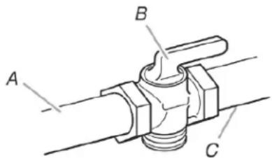
Install a manual gas line shut-off valve in an easily accessible location. Do not block access to shut-off valve. The valve is f turning on or shutting off gas to the cooktop.
text_image
A B CA. Gas supply line
B. Shut-off valve "open" position
C. To range
Gas Pressure Regulator
The gas pressure regulator supplied with this cooktop must be used. The inlet pressure to the regulator should be as follows for proper operation:
Natural Gas:
Minimum pressure: 5" (12.7 cm) WCP, 1.2 kPa (0.17 psi)
Maximum pressure: 7" to 14" (17.8 cm to 35.5 cm) WCP, 1.7 kPa (0.24 psi) to 3.5 kPa (0.50 psi)
Propane Gas:
Minimum pressure: 10" (25.4 cm) WCP, 2.7 kPa (0.39 psi)
Maximum pressure: 14" (35.5 cm) WCP, 3.6 kPa (0.50 psi)
Contact local gas supplier if you are not sure about the inlet pressure.
Burner Input Requirements
Input ratings shown on the model/serial/rating plate are for elevations up to 2,000 ft (609.6 m).
For elevations above 2,000 ft (609.6 m), ratings should be reduced at a rate of 4% for each 1,000 ft (304.8 m) above sea level (not applicable for Canada).
Gas Supply Pressure Testing
Gas supply pressure for testing regulator must be at least 1" (2.5 cm) (249 Pa) water column pressure above the manifold pressure shown on the model/serial/rating plate.
Line pressure testing above 1/2 psi (3.5 kPa) gauge 14" (35.5 cm) WCP
The cooktop and its individual shutoff valve must be disconnected from the gas supply piping system during any pressure testing of that system at test pressures in excess of 1/2 psi (3.5 kPa).
Line pressure testing at 1/2 psi (3.5 kPa) gauge 4" (35.5 cm) WCP or lower
The cooktop must be isolated from the gas supply piping system by closing its individual manual shut-off valve during any pressure testing of the gas supply piping system at test pressures equal to or less than 1/2 psi (3.5 kPa).
INSTALLATION
Install Cooktop
WARNING
Excessive Weight Hazard
Use two or more people to move and install or uninstall appliance.
Failure to do so can result in back or other injury.
Decide on the final location for the cooktop. Avoid drilling into or severing existing wiring during installation.
- Determine whether your cabinet construction provides clearance for installing clamping brackets at cooktop base ends. This is the recommended location. Clamping brackets can be installed on the front and back of cooktop base bottom, if necessary.
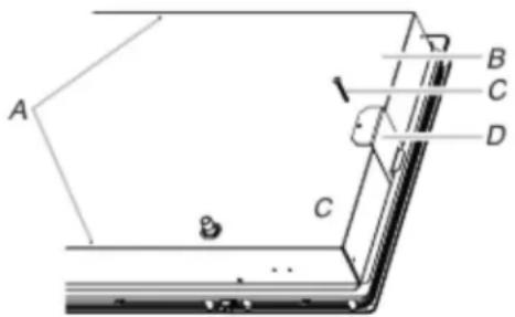
text_image
A B C D 1 CA. Attachment screw holes for optional front and back location
B. Cooktop base bottom
C. Attachment screw
D. Clamping bracket (end locations recommended)
- Using 2 or more people, place cooktop right side up into the cutout.
NOTE: Make sure that the front edge of the cooktop is parallel to the front edge of the countertop. If repositioning is needed, lift entire cooktop up from cutout to avoid scratching the countertop.
^ TEFLON ^® is a registered trademark of Chemours.
- Remove the attachment screws for the selected bracket locations from the bottom of the cooktop base.
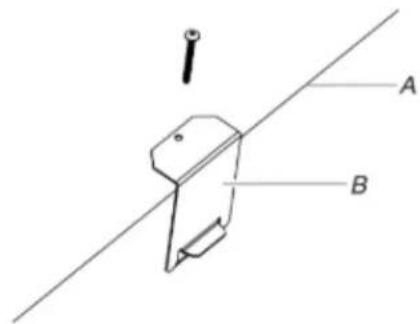
text_image
Technical diagram showing a mechanical component with labeled parts A and B, and a pointer indicating direction.A. Attachment screw holes for optional front and back location
B. Cooktop base bottom
- Attach brackets to cooktop base bottom with bracket attachment screws. Securely tighten screws.
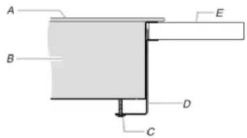
text_image
A B C D EA. Cooktop
B. Cooktop base
C. 2" (5.1 cm) bracket attachment screw
D. Clamping bracket (extends far enough beyond cooktop base to allow installation of clamping screws)
E. Countertop
Make Gas Connection
WARNING
Explosion Hazard
Use a new CSA International approved gas supply line. Install a shut-off valve.
Securely tighten all gas connections.
If connected to propane, have a qualified person make sure gas pressure does not exceed 14" (36 cm) water column.
Examples of a qualified person include: licensed heating personnel, authorized gas company personnel, and authorized service personnel.
Failure to do so can result in death, explosion, or fire.
Typical flexible connection
-
Apply pipe-joint compound made for use with Natural and propane gas to the smaller thread ends of the flexible connector adapters (see C and G in the following illustration).
-
Attach one adapter to the gas pressure regulator and the other adapter to the gas shutoff valve. Tighten both adapters.
-
Use a 15/16" (2.4 cm) combination wrench and channel lock pliers to attach the flexible connector to the adapters. Check that connector is not kinked.
IMPORTANT: All connections must be wrench-tightened. Do not make connections to the gas regulator too tight. Making the connections too tight may crack the regulator and cause a gas leak. Do not allow the regulator to turn when tightening fittings.
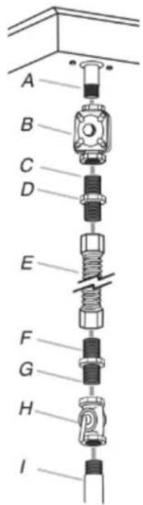
text_image
A B C D E F G H I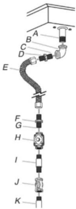
text_image
A B C D E F G H I J KA. Manifold entrance
B. Gas pressure regulator
C. Use pipe-joint compound.
D. Adapter (must have 1/2" (1.3 cm) male pipe thread)
E. Flexible connector
F. Adapter
G. Use pipe-joint compound.
H. Manual gas shutoff valve
- 1/2" (1.3 cm) or 3/4" (1.9 cm) gas pipe
A. Manifold entrance
B. 3/4" (1.9 cm) elbow
C. Use pipe-joint compound.
D. Adapter (must have 3/8" (9.5 mm) male pipe thread)
E. Flexible connector (pass through wall between cabinets)
F. Adapter (must have 3/8" (9.5 mm) male pipe thread)
G. Use pipe-joint compound.
H. Appliance pressure regulator (supplied)
- 1/2" (1.3 cm) or 3/4" (1.9 cm) gas pipe
J. Manual gas shutoff valve
K. 1/2" (1.3 cm) or 3/4" (1.9 cm) gas pipe
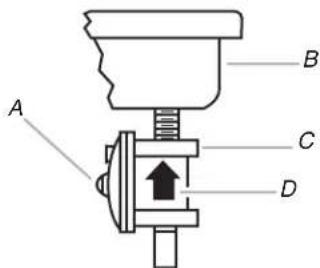
- Install the pressure regulator with the arrow pointing in the direction toward the bottom of the cooktop base and in a position where you can reach the regulator access cap.
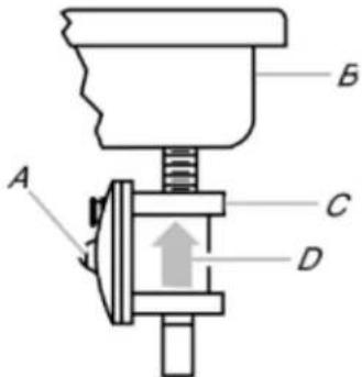
text_image
A B C DA. Access cap
B. Rear of cooktop
C. Gas pressure regulator
D. Up arrow. Regulator must be installed with arrow pointing up to cooktop bottom
IMPORTANT: Use only pipe-joint compound made for use with Natural and propane gas. Do not use TEFLONE. You will need to determine the fittings required depending on your installation.
Complete Connection
- Open the manual shutoff valve in the gas supply line. The valve is open when the handle is parallel to the gas pipe.
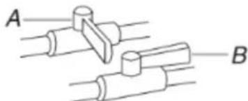
natural_image
Diagram of three mechanical components labeled A, B, and C, with no visible text or symbols.A. Closed valve
B. Open valve
-
Test all connections by brushing on an approved noncorrosive leak-detection solution. Bubbles will show a leak. Correct any leak found.
-
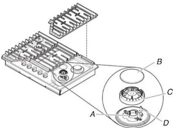
Remove surface burner caps, burner base and grates from parts package. Align notches in burner caps with pins in burner base.
Align orifice holder in burner base with igniter electrode. Burner caps should be level when properly positioned. If burner caps are not properly positioned, surface burners will not light. Place burner grates over burners and caps.
text_image
Technical diagram of a mechanical component with labeled parts A, B, C, D and internal featuresA. Orifice holder
B. Burner cap
C. Burner base
D. Igniter electrode
WARNING
Electrical Shock Hazard
Plug into a grounded 3 or 4 prong outlet.
Do not remove ground prong.
Do not use an adapter.
Do not use an extension cord.
Failure to follow these instructions can result in death, fire, or electrical shock.
- Plug into a grounded 3 prong outlet.
Complete Installation
Electronic Ignition System
Initial lighting and gas flame adjustments
Surface burners use electronic igniters in place of standing pilots. When the cooktop control knob is turned to the "IGNITE" position, the system creates a spark to light the burner. This sparking continues, as long as the control knob is turned to "IGNITE".
Check Operation of Surface Burners
Push in and turn the surface burners control knobs to light.
The surface burner flame should light within 4 seconds. The first time a surface burner is lit, it may take longer than 4 seconds to light because of air in the gas line.
Check the flame on "HIGH" for a blue color. It should be clean and soft in character. No yellow tip, blowing or lifting of flame should occur. Occasional orange flashes are normal and reflect different elements in the air or gas.
After verifying the proper burner operation, turn the control knobs to "OFF."
If burners do not light properly:
■ Turn surface burner control knob to the "OFF" position.
■ Check that the power supply cord is plugged in and the circu breaker has not tripped or the fuse blown.
■ Check that the gas shutoff valve is set to the "open" position
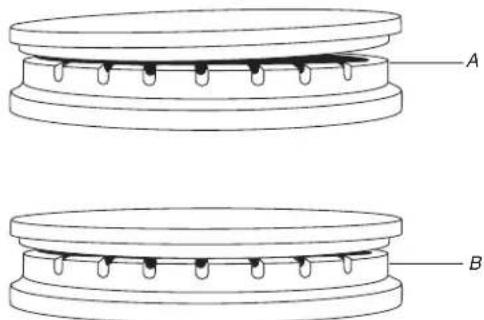
■ Check that burner caps are properly positioned on burner bases.
text_image
A BA. Incorrect
B. Correct
Recheck operation of surface burners. If a burner does not light this point, contact your dealer or authorized service company for assistance.
Check Flame Height
Adjust the height of surface burner flames.
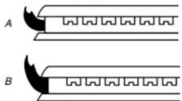
The surface burner low flame should be a steady blue flame approximately 1/4" (6.4 mm) high.
natural_image
Two identical mechanical or structural diagrams labeled A and B, showing gear-like components with no text or symbols.A. Low flame
B. High flame
Adjustment for Single Valve:
-
Set the burner flame to LO.
-
Remove the control knob.
-
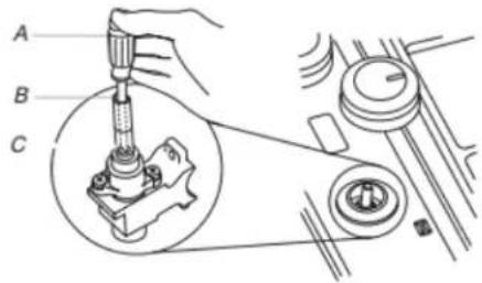
Hold knob stem with a pair of pliers. Use a 3/32" (#0 [2 mm]) flat-blade screwdriver to turn the screw located within the shaft of the control knob stem until the flame is the proper size. Turn adjustment screw "C" to the right to reduce flame height, turn adjustment screw to the left to increase flame height.
text_image
A B CA. 3/32" (#0 [2.0 mm]) flat-blade screwdriver (screwdriver shaft must be a minimum of 2" [5.1 cm] long)
B. Control knob stem opening
C. Adjustment screw location
-
Replace the control knob.
-
Test the flame by turning the control from LO to HI, checking the flame at each setting.
IMPORTANT: Dual valve adjustments must be performed by a qualified installer or service agency.
Power failure
In case of prolonged power failure, the surface burners can be lit manually. Hold a lit match near a burner and turn knob counterclockwise to IGNITE/Lite. After burner lights, turn knob to setting. Do not use a grill or griddle accessory during a power failure as the vent fan will not operate.
GAS CONVERSIONS
IMPORTANT: Gas conversions from Natural gas to Propane gas must be done by a qualified installer. Before proceeding with conversion, shut off the gas supply to the appliance prior to disconnecting the electrical power.

WARNING:
This conversion kit shall be installed by a qualified service agency in accordance with the manufacturer's instructions and all applicable codes and requirements of the authority having jurisdiction. If the information in these instructions is not followed exactly, a fire, an explosion or production of carbon monoxide may result causing property damage, personal injury or loss of life. The qualified service agency is responsible for the proper installation of this kit. The installation is not proper and complete until the operation of the converted appliance is checked as specified in the manufacturer's instructions supplied with the kit.
WARNING
Explosion Hazard
Use a new CSA International approved gas supply line. Install a shut-off valve.
Securely tighten all gas connections.
If connected to propane, have a qualified person make sure gas pressure does not exceed 14" (36 cm) water column.
Examples of a qualified person include: licensed heating personnel, authorized gas company personnel, and authorized service personnel.
Failure to do so can result in death, explosion, or fire.
Convert from Natural Gas to Propane Gas
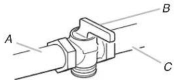
- Turn manual shut-off valve to the closed position.
text_image
A B CA. To cooktop
B. Shut-off valve (closed position)
C. Gas supply line
- Unplug cooktop or disconnect power.
To Convert Gas Pressure Regulator
text_image
A B C DA. Access cap
C. Gas pressure regulator
B. Rear of cooktop
D. Gas flow
- Determine the type of regulator you have:
Style 1: The cap has a slot and "NAT" printed on it.
Remove access cap by using a flat-blade screwdriver or coin, turning the access cap counterclockwise.
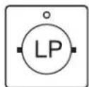
The gas pressure regulator has two settings that are stamped on either side of the cap. Turn the cap and reinstall into regulator with the stamp "LP" visible from the outside of the regulator.
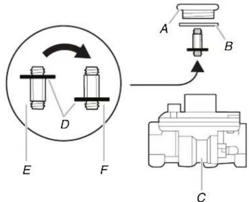
Style 2: The access cap has a slot in it or a hex shape, without any printed text.
Remove the access cap by using a flat-blade screwdriver or wrench turning the access cap counter clockwise.
If Seven Universe is printed on the regulator, unthread the spring retainer by rotating it counter clockwise. If Maxitrol is printed on the regulator then apply force to the flat side of the spring retainer to remove it.
Turn over the spring retainer to place the disk on the spring retainer far from the access cap.
Install the Seven Universe spring retainer by turning it clockwise to thread it fully into the access cap, or for the Maxitrol spring retainer by applying pressure to snap the spring retainer into the access cap.
Reinstall the cap and seal onto the regulator by turning clockwise.
text_image
Technical diagram showing mechanical assembly with labeled parts A, B, C, D, E, F and directional arrows indicating rotation or movement.A. Access cap
B. Seal
C. Regulator
D. Disk on Spring Retainer
E. Spring Retainer in Natural Gas Position
F. Spring Retainer in LP Gas Position
- Test the gas pressure regulator and gas supply line.
The regulator must be checked at a minimum 1" (2.5 cm) water column above the set pressure. The inlet pressure to the regulator should be as follows for operation and checking the regulator setting:
Propane Gas:
Minimum pressure: 10" (25.4 cm) WCP
Supply pressure: 14" (35.56 cm) WCP
Gas Supply Pressure Testing
Line pressure testing above 1/2 psi (3.5 kPa) gauge 14" (35.5 cm) WCP
The cooktop and its individual shut-off valve must be disconnected from the gas supply piping system during any pressure testing of that system at test pressures in excess of 1/2 psi (3.5 kPa).
Line pressure testing at 1/2 psi (3.5 kPa) gauge 14" (35.5 cm) WCP or lower
The cooktop must be isolated from the gas supply piping system by closing its individual manual shut-off valve during any pressure testing of the gas supply piping system at test pressures equal to or less than 1/2 psi (3.5 kPa).
- If the burner grates are installed, remove them.
Use the following chart to match the correct gas orifice spud with the burner location and model being converted.
Propane Gas Orifice Spud Chart
| Model Family | Burner | Burner Rating (BTU) | Color | Stamp (A) | Size (mm) |
| WCG-K3030P, WCG-K5030P | Right Front | 6500 | BLACK 80 0 | 8 | |
| Left Front | 11000 | GREEN 100 | 1 | ||
| Right Rear | 11000 | GREEN 100 | 1 | ||
| Left Rear | 4000 | RED 60 0.6 | |||
| Center | N/A N/A | N/A N/A | |||
| WCG-K5036P, WCG-K7030P, WCG-K7530P, WCG-K7536P | Right Front | 6500 | BLACK 80 0 | 8 | |
| Left Front | 11000 | GREEN 100 | 1 | ||
| Right Rear | 6500 | BLACK 80 0 | 8 | ||
| Left Rear | 4000 | RED 60 0.6 | |||
| Center | 11000 | GREEN 100 1 | |||
| WCG-K7036P | Right Front | 9000 | YELLOW | 90 0.9 | |
| Left Front | 11000 | GREEN 100 | 1 | ||
| Right Rear | 9000 | YELLOW | 90 0.9 | ||
| Left Rear | 4000 | RED 60 0.6 | |||
| Center | 11000 | GREEN 100 1 |
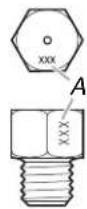
A. Stamp
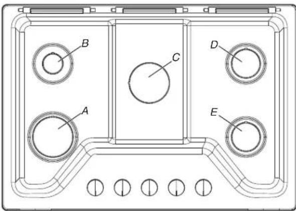
Burner Locations
text_image
A B C D EA. Left front
B. Left rear
C. Center
D. Right rear
E. Right front
- Remove all burner caps and burner bases (see the Quick Start Guide for burner reference).
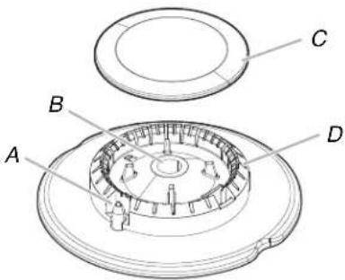
text_image
Technical diagram of a mechanical component with labeled parts A, B, C, and DStandard Flame
A. Igniter electrode
B. Gas tube opening
C. Burner cap
D. Burner base
7. To Convert Standard Burner:
■ Use 7.0 mm wrench to loosen and remove the orifice spud (A).
■ Set gas orifice spud aside.
■ Replace with correct Propane gas orifice spud. See Propane gas orifice spud chart.
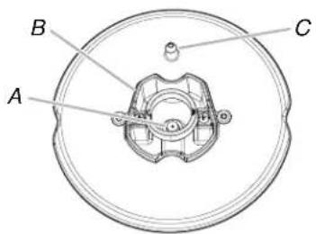
text_image
A B CA. Orifice spud
B. Orifice spud holder
C. Spark electrode
- Replace sheet of insulation.
- Replace burner bases and burner caps.
The igniter electrode is ceramic and could break during conversion. Be sure that the electrode comes through the hole in the burner smoothly while you are replacing the burner base.
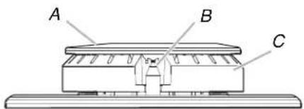
text_image
A B CA. Burner cap
B. Electrode
C. Burner base
- Open shutoff valve in the gas supply line. The valve is open when the handle is parallel to the gas pipe.
WARNING
Electrical Shock Hazard
Plug into a grounded 3 prong outlet.
Do not remove ground prong.
Do not use an adapter.
Do not use an extension cord.
Failure to follow these instructions can result in death, fire, or electrical shock.
- Plug in cooktop or reconnect power.
REMEMBER: Once you have completed converting all of the cooktop burners, test the cooktop for leaks by brushing on an approved noncorrosive leak-detection solution. If bubbles appear, a leak is indicated. Correct any leaks found.
- To adjust single and dual valves, see the "Complete Installation" section.
Convert from Propane Gas to Natural Gas
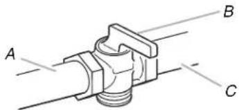
- Turn manual shut-off valve to the closed position.
text_image
A B CA. To cooktop
B. Shut-off valve (closed position)
C. Gas supply line
- Unplug cooktop or disconnect power.
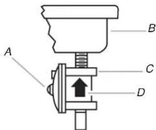
To Convert Gas Pressure Regulator
text_image
A B C DA. Access cap
B. Rear of cooktop
C. Gas pressure regulator
D. Gas flow
- Determine the type of regulator you have:
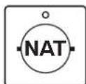
Style 1: The cap has a slot and "LP" printed on it.
Remove access cap by using a flat-blade screwdriver or coin, turning the access cap counterclockwise.
The gas pressure regulator has two settings which are
stamped on either side of the cap. Turn the cap and reinstall into regulator with the stamp "NAT" visible from the outside of the regulator.
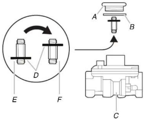
Style 2: The access cap has a slot in it or a hex shape, without any printed text.
Remove the access cap by using a flat-blade screwdriver or wrench turning the access cap counter clockwise.
If Seven Universe is printed on the regulator, unthread the spring retainer by rotating it counter clockwise. If Maxitrol is printed on the regulator then apply force to the flat side of the spring retainer to remove it.
Turn over the spring retainer to place the disk on the spring retainer close to the access cap.
Install the Seven Universe spring retainer by turning it clockwise to thread it fully into the access cap, or for the Maxitrol spring retainer by applying pressure to snap the spring retainer into the access cap.
Reinstall the cap and seal onto the regulator by turning clockwise.
text_image
Technical diagram showing mechanical assembly with labeled parts A, B, C, D, E, F and directional arrows indicating rotation or movement.A. Access cap
B. Seal
C. Regulator
D. Disk on Spring Retainer
E. Spring Retainer in LP Gas Position
F. Spring Retainer in Natural Gas Position
- If the burner grates are installed, remove them.
- If they are installed, remove the burner grates.
Use the following chart to match the correct gas orifice spud with the burner location and model being converted.
Natural Gas Orifice Spud Chart
| Model Family | Burner | Burner Rating (BTU) | Color | Stamp (A) | Size (mm) |
| WCG-K3030P, WCG-K5030P | Right Front | 9100 B | BLUE 130 1.30 | ||
| Left Front | 12000 | RED 150 1.5 | |||
| Right Rear | 18000 | BLACK 188 | 1.88 | ||
| Left Rear | 5000 | GREEN | 96 0.96 | ||
| Center | N/A | N/A | N/A | N/A | |
| WCG-K5036P, WCG-K7030P, WCG-K7530P, WCG-K7536P | Right Front | 9100 B | BLUE 130 1.30 | ||
| Left Front | 12000 | RED 150 1.5 | |||
| Right Rear | 9100 B | BLUE 130 1.30 | |||
| Left Rear | 5000 | GREEN | 96 0.96 | ||
| Center | 18000 | BLACK 188 | 1.88 |
| Model Family | Burner | Burner Rating (BTU) | Color | Stamp (A) | Size (mm) |
| WCG-K7036P | Right Front | 11000 | ORANGE | 143 1.43 | |
| Left Front | 12000 | RED 150 1.5 | |||
| Right Rear | 11000 | ORANGE | 143 1.43 | ||
| Left Rear | 5000 | GREEN | 96 0.96 | ||
| Center | 18000 | BLACK 188 | 1.88 |
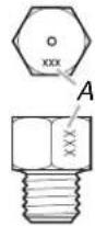
A. Stamp
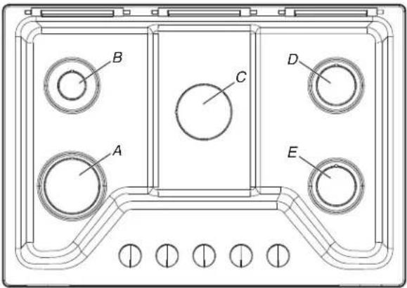
Burner locations
text_image
A B C D EA. Left front
B. Left rear
C. Center
D. Right rear
E. Right front
[Non-Text]
- Remove all burner caps and burner bases (see the Quick Start Guide for burner reference).
text_image
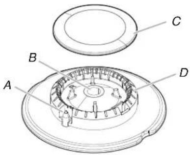
Technical diagram of a mechanical component with labeled parts A, B, C, and DStandard Flame
A. Igniter electrode
B. Gas tube opening
C. Burner cap
D. Burner base
7. To Convert Standard Burner:
■ Use 7.0 mm wrench to loosen and remove the orifice spud (A).
■ Set gas orifice spud aside.
■ Replace with correct Natural gas orifice spud. See Natural gas orifice spud chart.
text_image
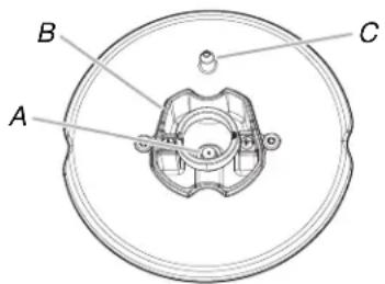
A B CA. Orifice spud
B. Orifice spud holder
C. Spark electrode
- Replace sheet of insulation.
- Replace burner bases and burner caps.
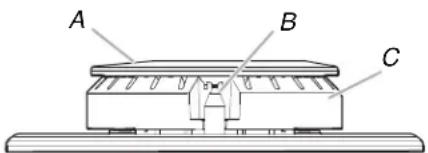
The igniter electrode is ceramic and could break during conversion. Be sure that the electrode comes through the hole in the burner smoothly while you are replacing the burner base.
text_image
A B CA. Burner cap
B. Electrode
C. Burner base
- Open shutoff valve in the gas supply line. The valve is open when the handle is parallel to the gas pipe.
WARNING

Electrical Shock Hazard
Plug into a grounded 3 prong outlet.
Do not remove ground prong.
Do not use an adapter.
Do not use an extension cord.
Failure to follow these instructions can result in death, fire, or electrical shock.
- Plug in cooktop or reconnect power.
REMEMBER: Once you have completed converting all of the cooktop burners, test the cooktop for leaks by brushing on an approved noncorrosive leak-detection solution. If bubbles appear, a leak is indicated. Correct any leaks found.
- To adjust single and dual valves, see the "Complete Installation" section.
Lighting the Electronic Igniters
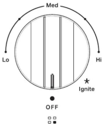
The cooktop burners use electronic igniters in place of standing pilots. When the cooktop control knob is pushed in and turned to Ignite, the system creates a spark to light the burner. This sparking continues until the control knob is turned to the desired setting.
To Check Operation of the Cooktop Burners:
- Push in and turn knobs to Ignite. The cooktop burner flame should light within 4 seconds. The first time a burner is lit, it may take longer than 4 seconds to light because of air in the gas line. Do not leave the knob in the ignition position after burner lights.
text_image
Med Lo Hi ★ Ignite OFF- If burners do not light properly, turn the control knob to OFF. Make sure the burner cap is in the proper position.
- Check that the power supply cord is plugged in and circuit breaker has been tripped or household fuse has not blown.
- Check that the shut-off valve is in the on position.
- Check burner operation again.
If one or all of the burners do not light at this point, refer to your Quick Start Guide for contact information.
Low Flame Height Adjustment
Each burner flame has been factory set to the lowest position available to provide reliable and constant reignition of the burner. However, each burner can be adjusted.
To Adjust:
- After lighting, push in and turn each control knob to the Lo position.
- If the burner does not stay lit on Lo, turn the control knob to ✦ Ignite until the burner lights.
- Quickly turn the control knob down to Lo. If the burner goes out after adjusting, readjust the valve.
To Readjust Valve:
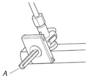
- Remove control knob(s).
- Insert a flat-blade screwdriver into the hollow valve stem and engage the slotted screw.
natural_image
Technical line drawing of a mechanical clamp or bracket assembly (no text or symbols)A. Valve stem on standard burner
- The flame size can be increased or decreased by turning the screw. Adjust flame until you can quickly turn the control kno from the Hi to Lo position without extinguishing the flame. The flame should be as small as possible without going out.
NOTE: For higher altitudes, no further burner adjustments are necessary.
Complete Burner Adjustment
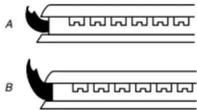
- Check burner flame(s) for proper size and shape. The cooktop low burner flame should be a steady blue flame approximated 1/4" (6.4 mm) high.
natural_image
Diagram showing two types of mechanical or electrical components labeled A and B, with no visible text or symbols.A. Low flame
B. High flame
- Completely fill out the conversion label and attach label to bottom of the cooktop next to the rating tag. Do not cover t rating tag with the conversion label.
IMPORTANT:
Place gas orifice spuds in plastic parts bag for future use and keep with package containing literature.
Read "Sealed Surface Burners" section in the Online Control Guide.
Moving the Cooktop
WARNING

Electrical Shock Hazard
Disconnect power before servicing.
Failure to do so can result in death or electrical shock.
WARNING

Explosion Hazard
Use a new CSA International approved gas supply line.
Install a shut-off valve.
Securely tighten all gas connections.
If connected to propane, have a qualified person make sure gas pressure does not exceed 14" (36 cm) water column.
Examples of a qualified person include: licensed heating personnel, authorized gas company personnel, and authorized service personnel.
Failure to do so can result in death, explosion, or fire.
WARNING
Excessive Weight Hazard
Use two or more people to move and install or uninstall appliance.
Failure to do so can result in back or other injury.
If removing the cooktop is necessary for cleaning or maintenance:
- Disconnect Power.
- Shut gas line off.
- Disconnect the flexible stainless steel connector.
- Unscrew mounting brackets.
- Using two or more people, place the cooktop on a covered surface.
- Complete cleaning or maintenance.
- Reinstall cooktop using the "Install Cooktop" section of your Owner's Manual.
SÉCURITÉ DE LA TABLE DE CUISSON
natural_image
Simple line drawing of a hand holding a curved object with a rectangular block (no text or symbols)natural_image
Two abstract line drawings: one with scattered dots and one with curved lines and a rectangular shape (no text or symbols)natural_image
Illustration of a hand cleaning a textured surface with wavy patterns (no text or symbols)natural_image
Simple diagram with a labeled point A and scattered dots, no text or symbols presenttext_image
A D C B M K E F G J L H I JNational Fire Protection Association
1 Batterymarch Park
Quincy, MA 02169-7471
CSA International
8501 East Pleasant Valley Road
Cleveland, OH 44131-5575
natural_image
Simple diagram of a horizontal beam with two flanged ends and a central span (no text or symbols)text_image
Technical diagram showing a mechanical component with labeled parts A and B, and a tool or probe inserted into the top part.text_image
A B C D E F G H IA. Entrée de la tubulure de distribution
B. Détendeur
E. Raccord flexible F. inclus
text_image
A B C D E F G H I J KA. Entrée de la tubulure de distribution
B. Coude de 3/4 po (1,9 cm)
natural_image
Pure mechanical assembly diagram showing two cylindrical components labeled A and B, without any text or symbols.A. Robinet fermé
B. Robinet ouvert
text_image
Technical diagram of a mechanical assembly with labeled components A, B, C, D and internal gears or housing layoutnatural_image
Technical line drawing of a mechanical component with labeled section A (no text or symbols beyond label)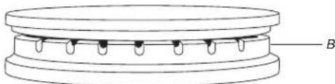
natural_image
Technical line drawing of a mechanical component with labeled part B (no text or symbols beyond label)A. Incorrect
B. Correct
natural_image
Two identical diagrams of a mechanical or electrical component with serrated edges and wavy internal patterns, labeled A and B (no text or symbols beyond labels)text_image
Technical diagram showing mechanical assembly with labeled parts A, B, C, D, E, F and directional arrows indicating rotation or movement.text_image
Technical diagram of a mechanical component with labeled parts A, B, C, and DFlamme ordinaire