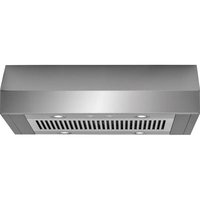
FHWC3650SS - Range hood FRIGIDAIRE - Free user manual and instructions
Find the device manual for free FHWC3650SS FRIGIDAIRE in PDF.


| Brand | Frigidaire |
| Model | FHWC3650SS |
| Product Type | Range Hood |
| Width | 36 in (91.4 cm) |
| Power Supply | 120 V, 60 Hz, 15 A (dedicated circuit) |
| Number of Speeds | 3 (Hi/Med/Lo) |
| Lighting | Front and rear LED (part number 5304503879) |
| Exhaust Type | Rectangular duct 3¼” x 10” (8.3 x 25.4 cm) or recirculation (optional kit) |
| Maximum Duct Length | 35 ft (10.7 m) |
| Grease Filters | Dishwasher safe (2 included) |
| Exterior Material | Stainless steel smudge-proof (Smudge-Proof™) |
| Surface Care | Warm soapy water or 50/50 water/vinegar solution |
| Warranty | 1-year limited (parts and labor) |
| Certification | Residential use only |
| Approximate Weight | Approximately 15 kg (estimate) |
Frequently Asked Questions - FHWC3650SS FRIGIDAIRE
User questions about FHWC3650SS FRIGIDAIRE
0 question about this device. Answer the ones you know or ask your own.
Ask a new question about this device
Download the instructions for your Range hood in PDF format for free! Find your manual FHWC3650SS - FRIGIDAIRE and take your electronic device back in hand. On this page are published all the documents necessary for the use of your device. FHWC3650SS by FRIGIDAIRE.
USER MANUAL FHWC3650SS FRIGIDAIRE
Installation, Use & Care
of your Range Hood

natural_image
Line drawing of various household appliances including washing machines, refrigerators, and a refrigerator (no text or symbols)Important Safety Instructions 3
List of materials 5
Electrical requirements 5
Location requirements 6
Product dimensions 6
Venting Requirements 7
Prepare the location 8
Install Range Hood (Ducted version) 10
Make Electrical Connection 11
Range Hood Use 12
Range Hood Care 13
Troubleshooting 15
Warranty Information 16
WELCOME & CONGRATULATIONS
Questions?
1-800-374-4432
(United States)
1-800-265-8352
(Canada)
Please attach sales receipt here for future reference.
Congratulations on your purchase of a new range hood! At Electrolux Home Products, we are very proud of our product and are completely committed to providing you with the best service possible. Your satisfaction is our number one priority.
We know you'll enjoy your new range hood and Thank You for choosing our product. We hope you consider us for future purchases.
PLEASE CAREFULLY READ AND SAVE THESE INSTRUCTIONS
This Use & Care Manual provides specific operating instructions for your model. Use your range hood only as instructed in this manual. These instructions are not meant to cover every possible condition and situation that may occur. Common sense and caution must be practiced when installing, operating and maintaining any appliance.
Please record your model and serial numbers below for future reference.
Model Number: ____
Serial Number: ____
Purchase Date: ____
NEED HELP?
Visit the Frigidaire Web Site at: http://www.frigidaire.com
Before you call for service, there are a few things you can do to help us serve you better.
Read this manual.
It contains instructions to help you use and maintain your range hood properly.
If you received a damaged range hood... immediately contact the dealer (or builder) that sold you the range hood.
Save time and money.
Check the section titled "Troubleshooting". This section helps you solve common problems that might occur. If you do need service, you can relax knowing help is only a phone call away. A list of toll-free customer service numbers is included in the back of this manual. Or call Frigidaire Customer Services at 1-800-374-4432, Monday through Saturday from 8 am to 8 pm Eastern Standard Time.
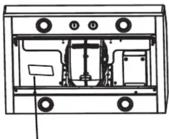
Serial Plate Location
Hinge down the vent grille and remove the grease filters. Refer to page 13 for additional information
natural_image
Technical line drawing of a device casing with internal components and mounting holes (no text or symbols)The serial plate is located on the left inside of the range hood
IMPORTANT SAFETY INSTRUCTIONS
Read all instructions before using this appliance.
Save these instructions for future references
Approved for residential appliances
For residential use only
Do not attempt to install or operate your appliance until you have read the safety precautions in this manual. Safety items throughout this manual are labeled with a WARNING or CAUTION based on the risk type.
This is the safety alert symbol. It is used to alert you to potential personal injury hazards. Obey all safety messges that follow this symbol to avoid possible injury or death.

WARNING
This symbol alerts you to situations that may cause serious body harm, death or property damage.

CAUTION
CAUTION indicates a potentially hazardous situation which, if not avoided, may result in minor or moderate injury.

IMPORTANT
IMPORTANT indicates installation, operation, maintenance or valuable information that is not hazard related.
IMPORTANT SAFETY INSTRUCTIONS

CAUTION
FOR GENERAL VENTILATING USE ONLY. DO NOT USE TO EXHAUST HAZARDOUS OR EXPLOSIVE MATERIALS OR VAPORS.

WARNING
TO REDUCE THE RISK OF FIRE, ELECTRIC SHOCK, OR INJURY TO PERSONS, OBSERVE THE FOLLOWING:
A. Use this unit only in the manner intended by the manufacturer. If you have questions, contact the manufacturer
B. Before servicing or cleaning the unit, switch power off at service panel and lock service panel disconnecting means to prevent power from being switched on accidentally. When the service disconnecting means cannot be locked, securely fasten a prominent warning device, such as a tag, to the service panel.
C. Installation Work and Electrical Wiring Must Be Done By Qualified Person(s) In Accordance With all Applicable Codes & Standards, Including Fire-rated Construction.
D. Sufficient air is needed for proper combustion and exhausting of gases through the flue (Chimney) of fuel burning equipment to prevent back- drafting. Follow the heating equipment manufacturers guideline and safety standards such as those published by the National Fire Protection Association (NFPA), the American Society for Heating, Refrigeration and Air Conditioning Engineers (ASHRAE), and the local code authorities.
E. When cutting or drilling into wall or ceiling, do not damage electrical wiring and other hidden utilities.
F. Ducted systems must always be vented to the outdoors.

CAUTION
To reduce risk of fire and to properly exhaust air, do not vent exhaust air into spaces within walls, ceilings, attics, crawl spaces, or garages.

WARNING
TO REDUCE THE RISK OF FIRE, USE ONLY METAL DUCT WORK.
Install this hood in accordance with all requirements specified.
IMPORTANT SAFETY INSTRUCTIONS

WARNING
To Reduce The Risk Of Fire Or Electric Shock, Do Not Use This Hood With Any External Solid State Speed Control Device.

WARNING
TO REDUCE THE RISK OF A RANGE TOP GREASE FIRE.
a) Never leave surface units unattended at high settings. Boilovers cause smoking and greasy spillovers that may ignite. Heat oils slowly on low or medium settings.
b) Always turn hood ON when cooking at high heat or when flambeing food (i.e. Crepes Suzette, Cherries Jubilee, Peppercorn Beef Flambe').
c) Clean ventilating fans frequently. Grease should not be allowed to accumulate on fan or filter.
d) Use proper pan size. Always use cookware appropriate for the size of the surface element.

WARNING
TO REDUCE THE RISK OF INJURY TO PERSONS, IN THE EVENT OF A RANGE TOP GREASE FIRE, OBSERVE THE FOLLOWING:
a) SMOTHER FLAMES with a close - fitting lid, cookie sheet, or other metal tray, then turn off the gas burner or the electric element. BE CAREFUL TO
PREVENT BURNS. If the flames do not go out immediately, EVACUATE AND CALL THE FIRE DEPARTMENT.
b) NEVER PICK UP A FLAMING PAN - you may be burned.
c) DO NOT USE WATER, including wet dishcloths or towels - a violent steam explosion will result.
d) Use an extinguisher ONLY if:
1) You know you have a class ABC extinguisher, and you already know how to operate it.
2) The fire is small and contained in the area where it started.
3) The fire department is being called.
4) You can fight the fire with your back to an exit.
OPERATION
Always leave safety grills and filters in place. Without these components, operating blowers could catch onto hair, fingers and loose clothing.
The manufacturer declines all responsibility in the event of failure to observe the instructions given here for installation, maintenance and suitable use of the product. The manufacturer further declines all responsibility for injury due to negligence and the warranty of the unit automatically expires due to improper maintenance.

CAUTION
Remove carton carefully. Wear gloves to protect against sharp edges.
LIST OF MATERIALS
Parts included in your hood
- 3 1/4" x 10" Rectangular vent damper
- 2 - Grease filters
• Use and Care / Installation Manual - Mounting screw kit
2 - 0.49 * 5.0 cm mounting screws
4 - 0.50 * 1.9 cm mounting screws
2 - plastic wall anchores
6 - 0.40 * 0.8 cm rectangular vent damper screws
Tools/Materials required
- Wire nuts
• Metal duct length to suit installation - Vent clamps/duct tape as required
- UL listed or CSA approved 1/2'' strain relief
- Remove the protective film covering the product before putting into operation.
- 5/64" drill bit for cabinet pilot holes
- Pencil
- Wire cutter / stripper
- Measuring tape
- Caulking gun and weatherproof caulking compound
- Flat-blade screwdriver
- Phillips screwdriver
- Saber or keyhole saw
- Safety glasses
- Gloves
For cabinets with recessed bottoms:
- Two - 2" (5.1 cm) wide filler strips. Length and thickness determined by recess dimensions.
- Four flat head wood screws or machine screws with washers and nuts (to attach filler strips).

NOTE
If configuring for recirculation venting, range hood model FHWC3050RS uses recirculation kit FHWRKT30RS and if using range hood model FHWC3650RSB recirculation kit FHWRKT36RS would be used.
ELECTRICAL REQUIREMENTS
Observe all governing codes and ordinances.
Ensure that the electrical installation is adequate and in conformance with National Electrical Code, ANSI/NFPA 70 (latest edition), or CSA Standards C22.1-94, Canadian Electrical Code, Part 1 and C22.2 No. 0-M91 (latest edition) and all local codes and ordinances.
If codes permit and a separate ground wire is used, it is recommended that a qualified electrician determine that the ground path is adequate.
A copy of the above code standards can be obtained from:
National Fire Protection Association
One Batterymarch Park
Quincy, MA 02269
CSA International
8501 East Pleasant Valley Road Cleveland, OH 44131-5575
- A 120 volt, 60 Hz., AC only, 15-amp, fused electrical circuit is required.
-
If the house has aluminum wiring, follow the procedure below:
-
Connect a section of solid copper wire to the pigtail leads.
-
Connect the aluminum wiring to the added section of copper wire using special conectors and/or tools designed and UL listed for joining copper to aluminum.
Follow the electrical connector manufacturer's recommended procedure. Aluminum/copper connection must conform with local codes and industry accepted wiring practices.
- Wire sizes and connections must conform with the rating of the appliance as specified on the model/serial rating plate.
The model/serial plate is located on the left side of the range hood.
- Wire sizes must conform to the requirements of the National Electrical Code, ANSI/NFPA 70 (la est edition), or CSA Standards C22. 1-94, Canad an Electrical Code, Part 1 and C22.2 No. 0-M91 (latest edition) and all local codes and ordinances.
LOCATION REQUIREMENTS

IMPORTANT
Observe all governing codes and ordinances.
- It is the installer's responsibility to comply with installation clearances.
- Range hood location should be away from strong draft areas, such as windows, doors and strong heating vents.
- Cabinet opening dimensions that are shown must be used. Given dimensions provide minimum clearance.
- Grounded electrical outlet is required. See "Electrical Requirements" section.
- All openings in ceiling and wall where canopy hood will be installed must be sealed.
For Mobile Home Installations
The installation of this range hood must conform to the Manufactured Home Construction Safety Standards, Title 24 CFR, Part 328 (formerly the Federal Standard for Mobile Home Construction and Safety, Title 24, HUD, Part 280) or when such standard is not applicable, the standard for Manufactured Home Installation 1982 (Manufactured Home Sites, Communities and Setups) ANSI A225.1/NFPA 501A, or latest edition, or with local codes.
Cabinet Dimensions
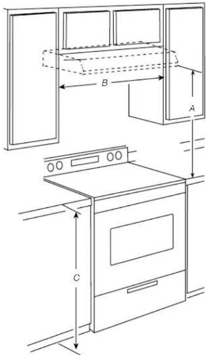
A. 24" (61.0 cm) min. for electric cooking surfaces 27" (68.6 cm) min. for gas cooking surfaces 30" (76.2 cm) suggested max.
B. 30" (76.2 cm) min. cabinet opening width for 30" (76.2 cm) models and 36" (91.4 cm) min. cabinet width for 36" (91.4 cm) models.
C. 36" (91.4 cm) base cabinet height
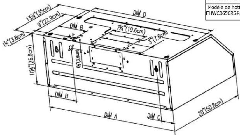
PRODUCT DIMENSIONS
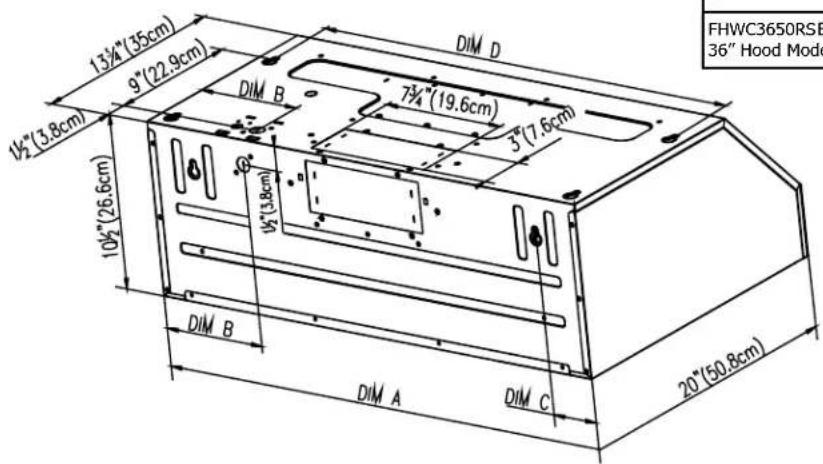
| hood model | Dim A | Dim B | Dim C | Dim D |
| FHWC3050RS 30" Hood Model | 29 7/8" (75.8 cm) | 6 1/2" (16.7 cm) | 3" (7.6cm) | 27 3/4" (70.5 cm) |
| FHWC3650RSB 36" Hood Model | 35 7/8"(91.1 cm) | 9 9/16" (24.3 cm) | 6'(15.2 cm) | 33 15/16" (86.2 cm) |
- Do not terminate the vent system into an attic or other enclosed area.
- Do not use a 4" (10.2 cm) laundry-type wall cap.
- Use metal vent only. Rigid metal vent is recommended. Plastic or metal foil vent is not recommended.
- The length of vent system and number of elbows should be kept to a minimum to provide efficient performance.
For the most efficient and quiet operation:
- Use no more than three 90^ elbows.
- Make sure there is a minimum of 24" (61 cm) of straight vent between the elbows if more than 1 elbow is used.
- Do not install 2 elbows together.
- Use clamps or duct tape to seal all joints in the vent system.
- The vent system at exit must have a cold air damper.
- Use caulking to seal exterior wall or roof opening around the cap.
- Best performances are reached with straight piping, without elbows and using smooth pipe.
Cold Weather Installations
An additional back draft damper should be installed to minimize backward cold air flow and a thermal break should be installed to minimize conduction of outside temperatures as part of the vent system. The damper should be on the cold air side of the thermal break.
The break should be as close as possible to where the vent system enters the heated portion of the house.
Makeup Air
Local building codes may require the use of makeup air systems when using ventilation systems greater than specified CFM of air movement. The specified CFM varies from locale to locale. Consult your HVAC professional for specific requirements in your area.
Venting Methods
Vent system can terminate either through the roof or wall. Use 314 " x 10" (8.3 x 25.4 cm) rectangular with a maximum vent length of 35 ft (10.7 m) for vent system.

NOTE
Flexible vent is not recommended. Flexible vent creates both back pressure and air turbulence that greatly reduce performance.
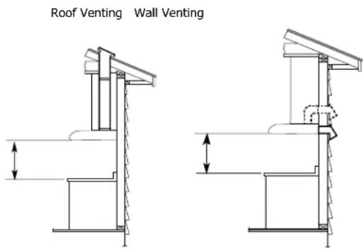
Calculating Vent System Length
To calculate the length of the system you need, add the equivalent feet (meters) for each vent piece used in the system.
These directions are for rectangular vent installation only. If you choose to use round rigid metal venting the minimum diameter to use is 8".
3 ^1/4 " x 10" (8.3 cm x 25.4 cm) rectangular Vent System
Vent Piece
3^1/4 x 10'' (8.3 cm x 25.4 cm) 5.0 ft 90^ elbow (1.5 m)

3¼" x 10" (8.3 cm x 25.4 cm) 12.0 ft flat elbow (3.7 m)
3¼" x 10" (8.3 cm x 25.4 cm) 0.0 ft wall cap (0.0 m)

Example Vent System
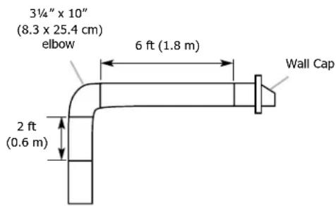
Maximum Recommended Length = 35 ft (10.7 m)
1 - 90° elbow = 5.0 ft (1.5 m) 8 ft (2.4 m) straight = 8.0 ft (2.4 m) 1 - wall cap = 0.0 ft (0.0 m)
Length of 314 " x 10" = 13.0 ft (3.9 m) (8.3 cm x 25.4 cm) system
VENTING REQUIREMENTS
PREPARE THE LOCATION

NOTE
Before making cutouts, make sure there is proper clearance within the ceiling, wall or cabinet. Fitting material is provided to secure the hood to most types of walls and cabinets. However, a qualified technician must verify suitability of the materials in accordance with the type of wall and cabinet.
- Disconnect power.
- Select a flat surface for assembling the range hood. Place covering over that surface.
- Lift the range hood and set it upside down onto covered surface.
- If cabinet has recessed bottom, add "two - 2" (5.1 cm) wide filler strips. Length and thickness determined by recess dimensions. Four flat head wood screws or machine screws with washers and nuts to attach filler strips in locations shown.
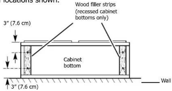
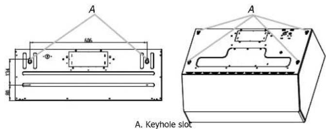
- Lift the range hood up under cabinet and determine final location by centering beneath cabinet. Mark on the underside of cabinet the location of the 4 keyhole mounting slots on the range hood (See slot dimensions on page 6). Mark rear mounting screw hole locations. Set range hood aside on a covered surface.
- Use 5/64" drill bit and drill 4 pilot holes as shown for top range hood support.
NOTE: Make the drill holes on the thin area of the slot.
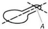
A. Drill pilot hole
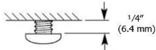
- Install the 4 - 0.50 cm x 1.9 cm mounting screws in pilot holes. Leave about 14 " (6.4 mm) space between screw heads and cabinet to slide range hood into place.
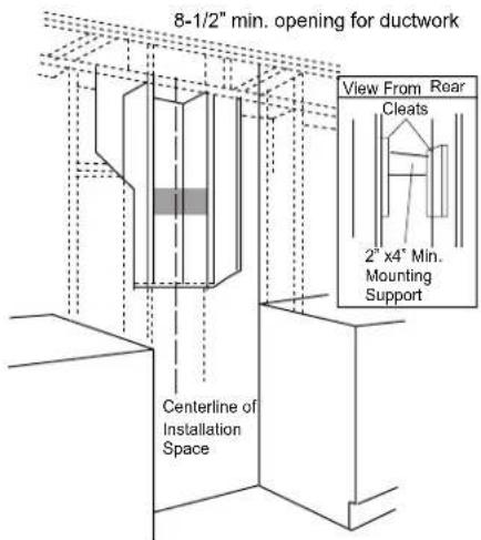
- Install framing for hood rear support If drywall is present, using the rear mounting screw hole locations marked in the previous step cut away enough drywall to expose 2 vertical studs at the rear mounting screw holes locations. Install horizontal support at least 2" X 4" between two wall studs at the rear mounting screw holes location. The horizontal support must be flush with the room side of the studs. Use cleats behind both sides of the support to secure to wall studs. Reinstall drywall and refinish. IMPORTANT – Framing must be capable of supporting 100 lbs.
PREPARE THE LOCATION
Determine Wiring Hole Location
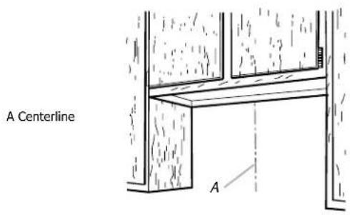
- Determine and clearly mark a vertical centerline on the wall and cabinet bottom.
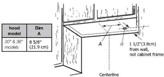
To wire through top:
- Mark a line distance (A) from the right of the centerline on the underside of the cabinet. Mark the point on this line that is 1 1/2"(3.8cm) from back wall. Drill a 1¼" (3.2 cm) diameter hole (B) through the cabinet at this point.
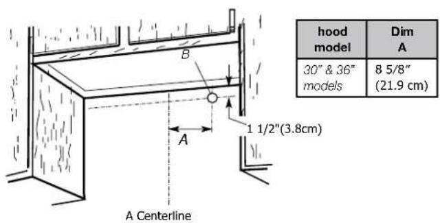
To wire through wall:
- Mark a line distance (A) from the right of the centerline on the underside of the wall. Mark the point on this line that is from 2th (3rd side of the cabinet. Drill a 1 14 (3.2 cm) diameter hole (B) through the rear wall at this point.
Roof Venting
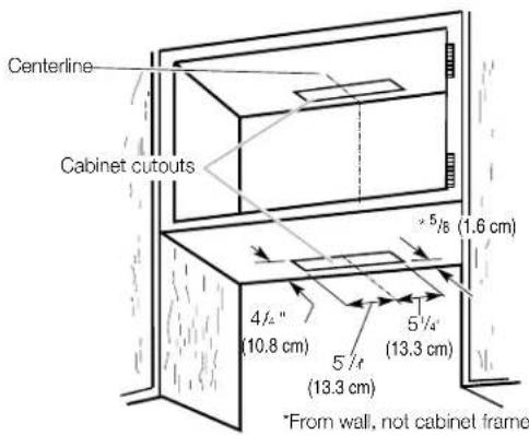
To make a 4¼" x 10½" (10.8 cm x 26.7 cm) rectangular cutout on the underside of cabinet top and bottom:
-
Mark lines 5(1.6 cm) and 4 " (10.8 cm) from the back wall on the centerline of the underside of cabinet.
-
Mark lines 5¼" (13.3 cm) to the right and left of the centerline on the underside of cabinet.
-
Use saber or keyhole saw to cut a rectangular opening for vent.
-
Repeat steps 1-3 for the underside of the top of the cabinet.
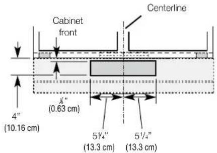
Wall Venting
To make a 414 " x 1012 " (10.8 cm x 26.7 cm) rectangle in the wall:
-
Make 2 lines by measuring 14'' (0.63 cm) and 4 (10.16 cm) down from underside of cabinet and mark on the centerline on the back wall.
-
Mark lines 5¼" (13.3 cm) to the right and left of the centerline on the wall.
-
Use saber or keyhole saw to cut a rectangular opening in the wall for the vent.
PREPARE THE LOCATION
Install Vent System
- Install vent through the vent opening in upper cabinet or wall. Complete venting system according to the selected venting method. See "Venting Requirements" section.
- Use caulking to seal exterior wall or roof opening around the cap.
INSTALL RANGE HOOD (Ducted version)
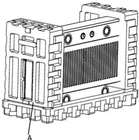
- Detach the 314 " x 10" (8.3 x 25.4 cm) rectangular vent damper from the package.
natural_image
Technical line drawing of a heat exchanger or cooling unit with labeled component A (no text or symbols beyond label)A. 3½" x 10" (8.3 x 25.4 cm) rectangular vent damper
For roof installations, remove the top rectangular vent knockout A. For wall installations, remove the rear rectangular vent knockout B.
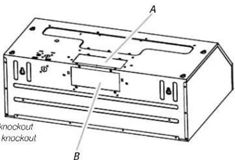
A. Top rectangular knockout B. Rear rectangular knockout
Vent Damper Installation
Install 3¼" x 10" (8.3 x 25.4 cm) vent damper. Attach to range hood using the indicated screws provided in hardware kit.
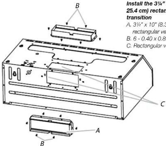
Install the 3 ^1/4 " x 10" (8.3 x 25.4 cm) rectangular vent transition
A. 3¼" x 10" (8.3 x 25.4 cm) rectangular vent transition
B. 6 - 0.40 x 0.80 cm screws
C. Rectangular vent knockouts
- If a vent damper is installed with a wall cap with damper, check that they do not interfere with each other. Remove the vent damper flap if they interfere.
Power Supply Cable Installation
- For direct wire installations, run the home power supply cable according to the National Electric Code or CSA standards and local codes and ordinances.
NOTE
Do not reconnect power until the installation is complete. Before starting the installation, remove the vent grill and grease filters.
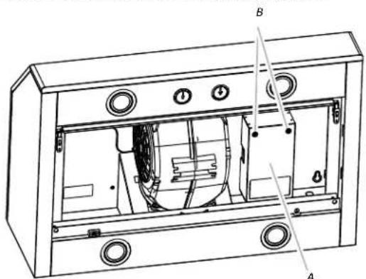
- Remove the screws from the terminal box cover. Remove terminal box cover and set aside.
natural_image
Technical line drawing of an open electrical enclosure with labeled components (A, B), showing internal wiring and mounting holes (no text or symbols beyond labels)A. Terminal box cover
B. Screw
INSTALLING THE HOOD
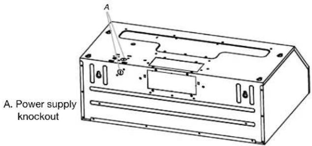
- Remove the power supply knockout from the top or rear of the vent hood (depending on the incoming location of your home power supply cable) and install a UL listed or CSA approved 12 " strain relief.
- Lift the hood into final position.
Feed enough electrical wire through the 1/2" UL listed or CSA approved strain relief to make connections in the terminal box. Tighten the strain relief screws.
- Position the range hood so that the large end of the keyhole slots are over the mounting screws.
Then push the hood toward the wall so that the screws are in the neck of the slots. Tighten the mounting screws, making sure the screws are in the narrow neck of slots.
-
Add the 2 rear 0.49 * 5.0 cm rear mounting screws into the narrow neck of the rear keyhole slots. These should screw into the horizontal support that was placed between the two wall studs in section PREPARE THE LOCATION on page 8.
-
Connect ventwork to hood. Seal joints with vent clamps or duct tape to make secure and airtight.
-
Check that back draft dampers work properly.
MAKE ELECTRICAL CONNECTION

WARNING
Electrical Shock Hazard
Disconnect power before servicing.
Replace all parts and panels before operating.
Failure to do so can result in death or electrical shock.
- Disconnect power.
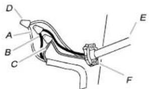
A. White wires
B. Black wires
C. Green ground wire
D. UL listed wire connector
E. Home power supply cable
F. UL listed or CSA approved
1/2 strain relief
-
Use UL listed wire connectors and connect white wires (A) together.
-
Use UL listed wire connectors and connect black wires (B) together.

WARNING
Fire Hazard
Electrically ground the blower. Use copper wire. Connect ground wire to green wire in terminal box. Failure to do so can result in death, fire, or electrical shock.
-
Connect green (or bare) ground wire from power supply to green wire in terminal box.
-
Install terminal box cover.

natural_image
Technical line drawing showing three sequential assembly steps of a mechanical housing or enclosure (no text or symbols present)- Reconnect power.
Complete Installation
-
Install grease filters. See the "Range Hood Use" section.
-
Check the operation of the range hood fan and light. See "Range Hood Use" section.
If range hood does not operate, check to see whether a circuit breaker has tripped or a household fuse has blown. Disconnect power and check wiring connections.

NOTE
To get the most efficient use from your new range hood, read the "Range Hood Use" section.
RANGE HOOD USE
RANGE HOOD USE
The range hood is designed to remove smoke and cooking vapors from the cooktop area. For best results, start the hood before cooking and allow it to operate several minutes after the cooking is complete to clear all smoke from the kitchen.
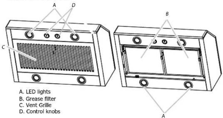
Range Hood Controls
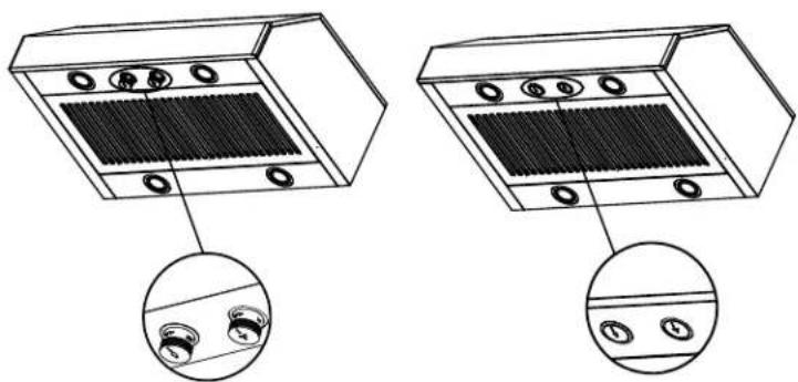
The hood controls are located at the bottom front section of the unit.

Operating the Light
Push in on knob to release and then rotate it counter clockwise for light On/Front/Rear/Off.
Operating the Fan
Push in on knob to release and then rotate it counter clockwise for fan speeds Hi/Med/Lo/Off.
natural_image
Technical line drawing of two identical electrical enclosure units with labeled buttons and internal components (no text or symbols)Cleaning

WARNING
To Reduce The Risk Of Fire Or Electrical shock disconnect from power supply before cleaning.

IMPORTANT
Clean the hood and grease filters frequently according to the following instructions. Replace grease filter before operating hood.

IMPORTANT
Exterior Surfaces
Do not use soap-filled scouring pads, abrasive cleaners, Cooktop Polishing Creme, steel wool, gritty washcloths or paper towels.
To avoid damage to the stainless steel, do not use cleaners that contain chlorine.
Cleaning Method:
SMUDGE-PROOF™ STAINLESS STEEL
Your range hood has Smudge-Proof ^TM Stainless Steel finish. Clean the stainless with warm soapy water using a clean sponge or cloth. Rinse with clean water and dry with a soft clean cloth. DO NOT USE any cleaners like Stainless Steel cleaners or any other types of cleaners containing any abrasive, chlorides, chlorines or ammonia. It is recommended to use mild dish soap and water or a 50/50 solution of water and vinegar.
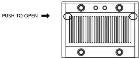
To clean or replace grease filter:
- Push in at the indicated area to open the vent grille. The vent grille will hinge down for access to the grease filters.
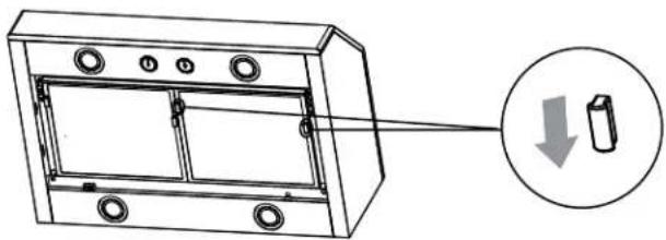
- To remove or install the grease filters push tab towards the back of the unit.
natural_image
Technical line drawing of a mechanical housing with a circular inset showing a downward arrow and a separate 3D component (no text or symbols)- To clean grease filter, soak the filters in hot water using a mild detergent. Rinse well and shake to dry.

NOTE
Do not use ammonia. The aluminum on the grease filter will corrode and darken.

NOTE
The grease filter is dishwasher safe. To avoid grease filter damage while cleaning, place filter into the dishwasher top rack for cleaning.

WARNING
Electrical Shock Hazard Disconnect power before servicing. Replace all parts and panels before operating. Failure to do so can result in death or electrical shock.
Replacing the Front LED lights
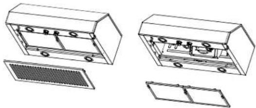
- Remove the vent grille and grease filters.
natural_image
Technical line drawings of a device showing internal components and structural sections (no text or symbols)- Remove the screws at the front support and slide the panel back.
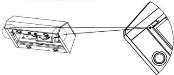
natural_image
Technical line drawing of a device with internal components and an external housing (no text or symbols)- Disconnect the front LED lights wiring
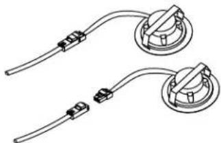
natural_image
Pure electrical circuit lines without any symbols- Squeeze LED lamp mounting clips and push down the LED lights as shown below
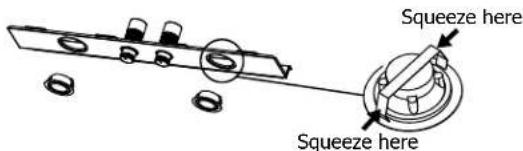
- Replace with new LED lights art number 5304503879 and re-install the front support
RANGE HOOD CARE

WARNING
Electrical Shock Hazard Disconnect power before servicing. Replace all parts and panels before operating. Failure to do so can result in death or electrical shock.
Replacing the Rear LED lights
- Remove the vent grille and grease filters.
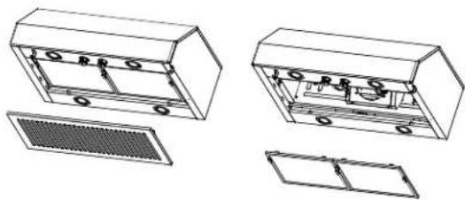
natural_image
Technical line drawings of a multi-case electrical enclosure with internal components and mounting brackets (no text or symbols)- Disconnect the rear LED lamp wiring
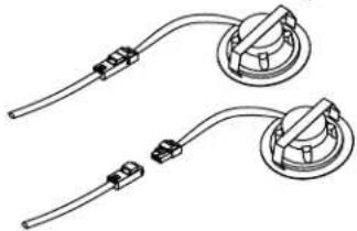
natural_image
Pure electrical circuit lines without any symbols- Squeeze LED lamp mounting clips and push down the LED lights as shown below.
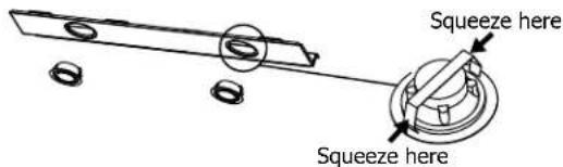
- Replace with new LED lights. art number 5304503879
TROUBLESHOOTING
Problem Possible Causes Solutions
| After installation, the unit doesn't work. | 1. The power line and the cable connector is not connected properly. | 1. Check the power connections. |
| 2. The wires from the switches are disconnected or loose. | 2. Make sure the wires on the switches are connected properly. | |
| Light works, but motor is not turning. | 1. The motor is defective, possible seized. | 1. Change the motor. |
| 2. Make sure the motor wire is plugged into the2. The motor terminal box connector. | ||
| The unit is vibrating. | 1. The motor is not secure in place. | 1. Tighten the motor in place. |
| 2. Damaged blower wheel. | 2. Change the blower. | |
| 3. The hood is not secured in place. | 3. Check the installation of the hood. | |
| The motor is working, but the lights are not. | 1. Defective lamp. | 1. Change the lamp. |
| 2. The lamp is loose. | Make sure the lamp is seated properly. | |
| 3. The wires on the light switch are loose. | Make sure the wires on light switch are connected properly. | |
| The hood is not venting out properly. | 1. The hood might be hanging to high from the cook top. | Check installation instructions. |
| 2. The wind from the opened windows or opened doors in the surrounding area are affecting the ventilation of the hood. | 2. Close all the windows and doors to eliminate the outside wind flow. | |
| 3. Blockage in the duct opening or duct work. | Remove all the blocking from the duct work or duct opening. | |
| 4. The direction of duct opening is against the wind. | Adjust the duct opening direction. | |
| 5. Using the wrong size of ducting. | 5. Change the ducting to correct size. | |
| Vent grill or grease filter is vibrating. | . Vent grill or grease filter is loose. | Make sure vent grill or grease filter is installed correctly. |
Warranty
Your appliance is covered by a one year limited warranty. For one year from your original date of purchase, Electrolux will pay all costs for repairing or replacing any parts of this appliance that prove to be defective in materials or workmanship when such appliance is installed, used and maintained in accordance with the provided instructions.
Exclusions
This warranty does not cover the following:
- Products with original serial numbers that have been removed, altered or cannot be readily determined.
- Product that has been transferred from its original owner to another party or removed outside the USA or Canada.
- Rust on the interior or exterior of the unit.
- Products purchased "as-is" are not covered by this warranty.
- Food loss due to any refrigerator or freezer failures.
- Products used in a commercial setting.
- Service calls which do not involve malfunction or defects in materials or workmanship, or for appliances not in ordinary household use or used other than in accordance with the provided instructions.
- Service calls to correct the installation of your appliance or to instruct you how to use your appliance.
- Expenses for making the appliance accessible for servicing, such as removal of trim, cupboards, shelves, etc., which are not a part of the appliance when it is shipped from the factory.
- Service calls to repair or replace appliance light bulbs, air filters, water filters, other consumables, or knobs, handles, or other cosmetic parts.
- Surcharges including, but not limited to, any after hour, weekend, or holiday service calls, tolls, ferry trip charges, or mileage expense for service calls to remote areas, including the state of Alaska.
- Damages to the finish of appliance or home incurred during installation, including but not limited to floors, cabinets, walls, etc.
- Damages caused by: services performed by unauthorized service companies; use of parts other than genuine Electrolux parts or parts obtained from persons other than authorized service companies; or external causes such as abuse, misuse, inadequate power supply, accidents, fires, or acts of God.
DISCLAIMER OF IMPLIED WARRANTIES; LIMITATION OF REMEDIES
CUSTOMER'S SOLE AND EXCLUSIVE REMEDY UNDER THIS LIMITED WARRANTY SHALL BE PRODUCT REPAIR OR REPLACEMENT AS PROVIDED HEREIN. CLAIMS BASED ON IMPLIED WARRANTIES, INCLUDING WARRANTIES OF MERCHANTABILITY OR FITNESS FOR A PARTICULAR PURPOSE, ARE LIMITED TO ONE YEAR OR THE SHORTEST PERIOD ALLOWED BY LAW, BUT NOT LESS THAN ONE YEAR. ELECTROLUX SHALL NOT BE LIABLE FOR CONSEQUENTIAL OR INCIDENTAL DAMAGES SUCH AS PROPERTY DAMAGE AND INCIDENTAL EXPENSES RESULTING FROM ANY BREACH OF THIS WRITTEN LIMITED WARRANTY OR ANY IMPLIED WARRANTY. SOME STATES AND PROVINCES DO NOT ALLOW THE EXCLUSION OR LIMITATION OF INCIDENTAL OR CONSEQUENTIAL DAMAGES, OR LIMITATIONS ON THE DURATION OF IMPLIED WARRANTIES, SO THESE LIMITATIONS OR EXCLUSIONS MAY NOT APPLY TO YOU. THIS WRITTEN WARRANTY GIVES YOU SPECIFIC LEGAL RIGHTS. YOU MAY ALSO HAVE OTHER RIGHTS THAT VARY FROM STATE TO STATE.
If You Need Service
Keep your receipt, delivery slip, or some other appropriate payment record to establish the warranty period should service be required. If service is performed, it is in your best interest to obtain and keep all receipts. Service under this warranty must be obtained by contacting Electrolux at the addresses or phone numbers below.
This warranty only applies in the USA and Canada. In the USA, your appliance is warranted by Electrolux Major Appliances North America, a division of Electrolux Home Products, Inc. In Canada, your appliance is warranted by Electrolux Canada Corp. Electrolux authorizes no person to change or add to any obligations under this warranty. Obligations for service and parts under this warranty must be performed by Electrolux or an authorized service company. Product features or specifications as described or illustrated are subject to change without notice.
USA
1.800.944.9044
Electrolux Home Products, Inc.
10200 David Taylor Drive
Charlotte, NC 28262

Electrolux
Canada
1.800.265.8352
Electrolux Canada Corp.
5855 Terry Fox Way
Mississauga, Ontario, Canada
L5V 3E4
FRIGIDAIRE
Tout sur
l'Installation,
natural_image
Line drawing of various household appliances including washing machines, refrigerators, and a refrigerator (no text or symbols)Please attach sales receipt here for future reference.
natural_image
Technical line drawing of a device casing with internal components and mounting holes (no text or symbols)National Fire Protection Association
One Batterymarch Park
Quincy, MA 02269
CSA International
8501 East Pleasant Valley Road Cleveland, OH 44131-5575
DIMENSIONS DU PRODUIT
| Modèle de hotte | Dim A Dim B | Dim C | Dim D | |
| Modèle de hotteFHWC3050RS 30" | 29 7/8" (75.8 cm) | 3" (7.6cm)6 1(16.7 cm) (16.7 cm) | 1/2" 27 3/4"(70.5 cm) | |
| Modèle de hotteFHWC3650RSB 36" | 35 7/8" (91.1cm) | 9 9/16"(24.3 cm) | 6'(15.2 cm) | 33 15/16"(86.2 cm) |
natural_image
Technical line drawing of two mechanical assembly configurations with dimension arrows (no text or symbols)natural_image
Technical line drawing of a heat exchanger or cooling unit with labeled component A (no text or symbols beyond label)natural_image
Technical line drawing of an open electrical enclosure with internal components and mounting holes (no text or symbols)natural_image
Technical line drawing showing three sequential assembly steps of a mechanical housing or enclosure (no text or symbols)natural_image
Technical line drawing of two household appliances with labeled buttons and internal components (no text or symbols)Nettoyage
AVERTISSEMENT
natural_image
Technical line drawing of a mechanical housing with a magnified inset showing a downward arrow and a cylindrical component (no text or symbols)natural_image
Technical line drawings of a multi-case electrical enclosure with internal components and ventilation grilles (no text or labels)natural_image
Technical line drawing of a device with a close-up view showing internal components (no text or symbols)natural_image
Pure electrical circuit lines without any symbolsnatural_image
Technical line drawing of a mechanical housing with internal components and a meshed base (no text or symbols)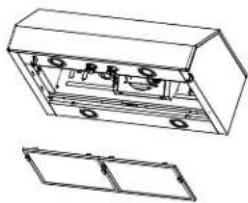
natural_image
Technical line drawing of a mechanical housing with internal components and a separate open panel (no text or symbols)natural_image
Technical line drawing of two mechanical or electrical components with coiled wires and connectors (no text or symbols)natural_image
Line drawing of various household appliances including washing machines, refrigerators, and a refrigerator (no text or symbols)Please attach sales receipt here for future reference.
natural_image
Technical line drawing of a device casing with internal components and mounting holes (no text or symbols)National Fire Protection Association
One Batterymarch Park
Quincy, MA 02269
CSA International
8501 East Pleasant Valley Road
Cleveland, OH 44131-5575
A. 24" (61.0 cm) mín. para superficies de cocinas eléctricas 27" (68,6 cm) mín. para superficies de cocinas a gas 30" (76.2 cm) máx. sugeridas
DIMENSIONES DEL PRODUCTO
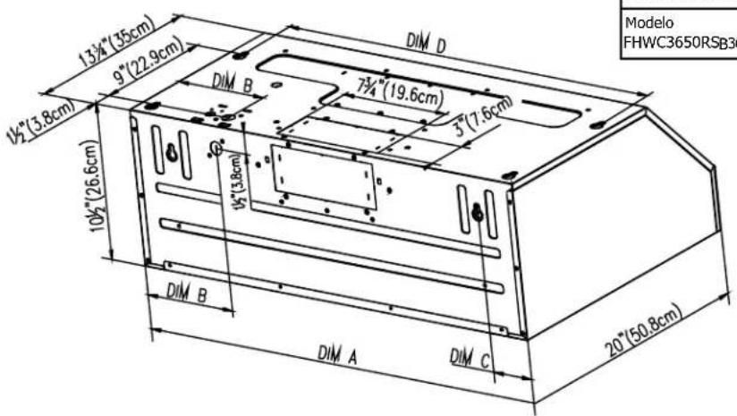
| Modelo de campana | Dim A | Dim B | Dim C | Dim D |
| ModeloFHWC3050RS 30" | 29 7/8"(75.8 cm) | (16.7 cm) (16.7 cm) | 3"(7.6cm)6 1/2"(70.5 cm) | 27 3/4"(70.5 cm) |
| ModeloFHWC3650RSB36" | 35 7/8"(91.1 cm) | 9 9/16"(24.3 cm) | 6'(15.2 cm) | 33 15/16"(86.2 cm) |
natural_image
Technical line drawing of two mechanical assembly configurations with dimension arrows (no text or symbols)natural_image
3D diagram of a mechanical part with labeled point A and internal features (no text or symbols)natural_image
Technical line drawing of a heat exchanger or cooling unit with labeled component A (no text or symbols beyond label)A. Amortiguador de ventilación rectangular de 3 ^1/4 " x 10" (8,3 x 25,4 cm)
natural_image
Technical line drawing of an open industrial enclosure with labeled components (A, B), showing internal wiring and mounting holes (no text or symbols beyond labels)natural_image
Technical line drawing of a rectangular electronic device casing with internal compartments and mounting holes (no text or symbols)A. Cables blancos
B. Cables negros
natural_image
Technical line drawing showing three sequential assembly steps of a mechanical housing or enclosure (no text or symbols)natural_image
Technical line drawing of two household appliances with labeled buttons and internal components (no text or symbols)Cleaning

ADVERTENCIA
natural_image
Technical diagram of a heat exchanger or radiator component with mounting holes and internal ribs (no text or symbols)natural_image
Technical line drawing of a mechanical housing with a magnified inset showing a downward arrow and a cylindrical component (no text or symbols)natural_image
Technical line drawings of a multi-case electrical enclosure with internal components and ventilation grilles (no text or labels)natural_image
Technical line drawing of a device with an optical lens and internal components (no text or symbols)natural_image
Pure electrical circuit lines without any symbolsnatural_image
Technical line drawing of a cabinet with internal components and a mesh cover (no text or symbols)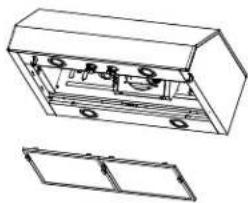
natural_image
Technical line drawing of a mechanical housing with internal components and a separate open panel (no text or symbols)natural_image
Pure electrical circuit lines without any symbols
- Installation, Use & Care
- WELCOME & CONGRATULATIONS
- PLEASE CAREFULLY READ AND SAVE THESE INSTRUCTIONS
- NEED HELP?
- Visit the Frigidaire Web Site at: http://www.frigidaire.com
- Read this manual.
- Save time and money.
- Serial Plate Location
- IMPORTANT SAFETY INSTRUCTIONS
- Read all instructions before using this appliance.
- WARNING
- CAUTION
- IMPORTANT
- TO REDUCE THE RISK OF FIRE, ELECTRIC SHOCK, OR INJURY TO PERSONS, OBSERVE THE FOLLOWING:
- TO REDUCE THE RISK OF FIRE, USE ONLY METAL DUCT WORK.
- TO REDUCE THE RISK OF A RANGE TOP GREASE FIRE.
- TO REDUCE THE RISK OF INJURY TO PERSONS, IN THE EVENT OF A RANGE TOP GREASE FIRE, OBSERVE THE FOLLOWING:
- OPERATION
- LIST OF MATERIALS
- Parts included in your hood
- Tools/Materials required
- For cabinets with recessed bottoms:
- NOTE
- ELECTRICAL REQUIREMENTS
- National Fire Protection Association
- CSA International
- LOCATION REQUIREMENTS
- Observe all governing codes and ordinances.
- For Mobile Home Installations
- Cold Weather Installations
- Makeup Air
- Venting Methods
- Calculating Vent System Length
- VENTING REQUIREMENTS
- PREPARE THE LOCATION
- Determine Wiring Hole Location
- To wire through top:
- To wire through wall:
- Roof Venting
- Wall Venting
- Install Vent System
- INSTALL RANGE HOOD (Ducted version)
- Vent Damper Installation
- Power Supply Cable Installation
- INSTALLING THE HOOD
- MAKE ELECTRICAL CONNECTION
- Fire Hazard
- Complete Installation
- RANGE HOOD USE
- Range Hood Controls
- Operating the Light
- Operating the Fan
- Cleaning
- Exterior Surfaces
- Cleaning Method:
- To clean or replace grease filter:
- Replacing the Front LED lights
- RANGE HOOD CARE
- Replacing the Rear LED lights
- TROUBLESHOOTING
- Warranty
- Exclusions
- This warranty does not cover the following:
- DISCLAIMER OF IMPLIED WARRANTIES; LIMITATION OF REMEDIES
- If You Need Service
- USA
- 1.800.944.9044
- Electrolux
- Canada
- 1.800.265.8352
- FRIGIDAIRE
- Tout sur
- l'Installation,
- DIMENSIONS DU PRODUIT
- Nettoyage
- AVERTISSEMENT
- DIMENSIONES DEL PRODUCTO
- ADVERTENCIA
Brand : FRIGIDAIRE
Model : FHWC3650SS
Category : Range hood