
DET3650RIDR - Refrigerator Sub-Zero - Free user manual and instructions
Find the device manual for free DET3650RIDR Sub-Zero in PDF.

| Product Type | Refrigerator |
| Brand | Sub-Zero |
| Model | DET3650RIDR |
| Category | Designer Series |
| Opening Dimensions (W x H x D) | 36 in x 84 in x 24 in (914 x 2134 x 610 mm) |
| Electrical Supply | 115 V AC, 60 Hz |
| Electrical Circuit | 15 A dedicated |
| Plug | Three-prong grounded |
| Water Supply | 1/4 in (6 mm) copper or PEX tubing, 35-120 psi (2.4-8.3 bar) |
| Cooling Type | Dual Refrigeration (two-circuit system) |
| Ice Maker | Yes, built-in |
| Water Dispenser | Yes (depending on finish) |
| Water Filtration System | Replaceable water filter |
| Interior Lighting | LED |
| Shelves | Adjustable, glass |
| Crisper Drawers | Yes, with humidity control |
| Anti-Tip Bracket | Included, mandatory |
| Custom Panels | Yes, min thickness 5/8 in (16 mm), max weight 75 lb (34 kg) for 36 in |
| Toe Kick | Removable |
| Door Stop | 90° or 105° adjustable |
| Customer Service | 800-222-7820 / subzero.com |
Frequently Asked Questions - DET3650RIDR Sub-Zero
User questions about DET3650RIDR Sub-Zero
0 question about this device. Answer the ones you know or ask your own.
Ask a new question about this device
Download the instructions for your Refrigerator in PDF format for free! Find your manual DET3650RIDR - Sub-Zero and take your electronic device back in hand. On this page are published all the documents necessary for the use of your device. DET3650RIDR by Sub-Zero.
USER MANUAL DET3650RIDR Sub-Zero
Designer Series Refrigeration
Installation Guide
SPECIFICATIONS, INSTALLATION, AND MORE

Contents
3 Designer Series Refrigeration
4 Opening Dimensions
5 Electrical Requirements
6 Plumbing Requirements
7 Preparation
8 Anti-Tip Bracket
10 Placement
10 Alignment
11 Water Line
12 Panels
14 Panel Installation
16 Completion
Features and specifications are subject to change at any time without notice. Visit subzero.com/specs for the most up-to-date information.
Important Note
To ensure this product is installed and operated as safely and efficiently as possible, take note of the following types of highlighted information throughout this guide:
IMPORTANT NOTE highlights information that is especially important.
CAUTION
Indicates a situation where minor injury or product damage may occur if instructions are not followed.
WARNING
States a hazard that may cause serious injury or death if precautions are not followed.
IMPORTANT NOTE: Throughout this guide, dimensions in parentheses are millimeters unless otherwise specified
IMPORTANT NOTE: Save these instructions for the local electrical inspector.
Product Information
Important product information, including the model and serial number, are listed on the product rating plate. For column models, the rating plate is located inside the middle drawer near the drawer guide opposite the hinge. For tall and drawer models, the rating plate is located inside the cabinet, to the left of the upper drawer. Refer to the illustrations below.
If service is necessary, contact Sub-Zero Factory Certified Service with the model and serial number. For the name of the nearest Sub-Zero Factory Certified Service or for questions regarding the installation, visit the Product Support section of our website, subzero.com, or call Sub-Zero Customer Care at 800-222-7820.
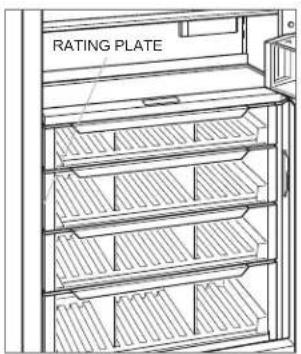
Column models
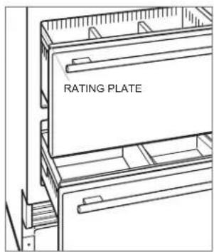
Tall and drawer models
Opening Dimensions
DESIGNER MODELS
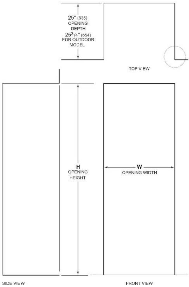
NOTE: 3 ^1/2 (89) finished returns will be visible and should be finished to match cabinetry—4 ^1/2 (114) for outdoor model.
OPENING DIMENSIONS
COLUMN / TALL WH
18" Column 18" (457) 84" (2134)
24" Column 24" (610) 84" (2134)
30" Column / Tall 30" (762) 84" (2134)
36" Column / Tall 36" (914) 84" (2134)
DRAWER WH
24" Drawer 24" (610) 34 ^1/2 " (876)
27" Drawer 27" (686) 34 ^1/2 " (876)
30" Drawer 30" (762) 34 ^1/2 " (876)
36" Drawer 36" (914) 34½" (876)
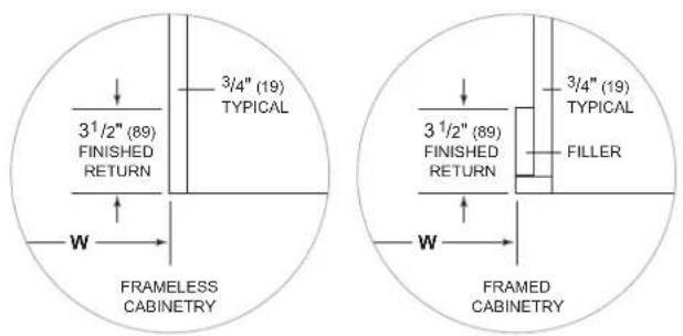
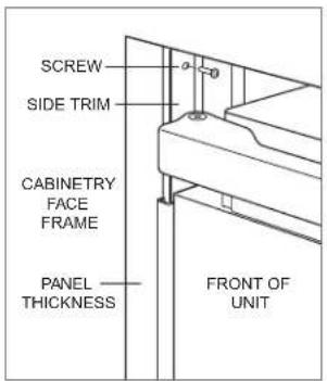
The depth of each designer model is 24" (610). Allow for panel thickness when planning the finished opening depth. A minimum 3½" (89) finished return is required on all sides of the opening—4½" (114) for the outdoor model. Framed cabinets require additional finished filler material behind the face frame for a proper installation. Refer to the illustration.
DUAL INSTALLATION
When installing two units side by side in a dual installation, the opening width is the width of the two units added together. A dual installation kit is required for this installation. If a dual installation kit is not specified, a minimum 2" (51) filler strip is required between the units.
Dual installation kits are available through an authorized Sub-Zero dealer. For questions regarding the installation, call Sub-Zero Customer Care at 800-222-7820.
Electrical Requirements
Installation must comply with all applicable electrical codes.
The electrical supply must be located within the shaded area shown in the illustration and chart below. A separate circuit servicing only this appliance is required.
IMPORTANT NOTE: For indoor models, a ground fault circuit interrupter (GFCI) is not recommended and may cause interruption of operation.
For the outdoor model, a ground fault circuit interrupter (GFCI) is required to reduce the risk of electrical shock.
The electrical outlet must be positioned with the grounding prong to the right of the thinner blades.
ELECTRICAL SUPPLY LOCATION A
| 18" Model 6" (152) |
| 24" Model 9 12 " (241) |
| 27" Model 11" (279) |
| 30" Model 12 12 " (318) |
| 36" Model 15 12 " (394) |
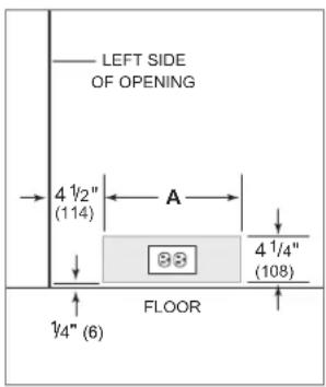
Electrical supply location
CAUTION
The outlet must be checked by a qualified electrician to be sure it is wired with the correct polarity. Verify the outlet is properly grounded.
WARNING
If the supply cord is damaged, it must be replaced by the manufacturer, its service agent or similarly qualified persons in order to avoid a hazard.
WARNING
Do not use an extension cord, two-prong adapter, or remove the power cord ground prong.
ELECTRICAL REQUIREMENTS
| Electrical Supply 115 VAC, 60 Hz |
| Service 15 amp dedicated circuit |
| Receptacle 3-prong grounding-type |
Plumbing Requirements
Installation must comply with all applicable plumbing codes.
Locate the water supply line within the shaded area shown in the illustration below. Connect the water supply line to the house supply with an easily accessible shut-off valve.
Do not use self-piercing valves. The water supply line must be flush with the floor and cannot interfere with the installation of the anti-tip bracket.
Column and tall models with an ice maker or water dispenser feature a water filtration system. An in-line filter is required for drawer models with an ice maker when water conditions have a high sediment content.
A reverse osmosis system can be used provided there is constant water pressure of 35–120 psi (2.4–8.3 bar) supplied to the unit at all times. In this application, the water filtration system must be bypassed. Refer to Water Filter Bypass on page 18. A copper line is not recommended for this application.
WATER SUPPLY LOCATION A
| 18" Model 3" (76) |
| 24" Model 5 12 " (140) |
| 30" Model 6" (152) |
| 36" Model 9" (229) |
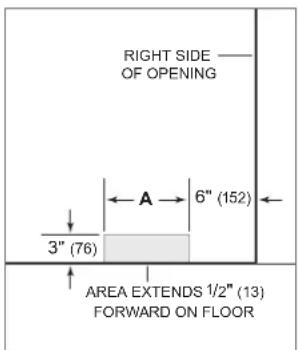
Water supply location
PLUMBING REQUIREMENTS
| Water Supply Line 1/4" OD copper, braided stainless steel, or PEX tubing |
Water Pressure 35–120 psi (2.4–8.3 bar)
Excess Water Line for Connection 36" (914)
Preparation
Uncrate the unit and inspect for damage. Remove the wood base and discard the shipping bolts and brackets. Remove and recycle packing materials. Do not discard the kickplate, anti-tip bracket, and hardware.
Remove the kickplate by extracting the two mounting screws. Refer to the illustration below.

Kickplate removal
Anti-Tip Bracket
WARNING
To prevent the unit from tipping forward, the anti-tip bracket must be installed.
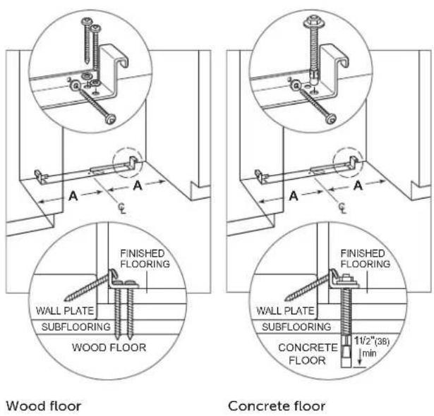
The back of the anti-tip bracket must be installed 24" (610) from the front of the unit (without panels). Use all the anti-tip bracket hardware as instructed for wood or concrete floors.
IMPORTANT NOTE: For wood or concrete floor applications, if the #12 screws do not hit a wall stud or wall plate, use the #8 screws and #12 washers with the wall anchors.
IMPORTANT NOTE: In some installations, the subflooring or finished floor may necessitate angling the screws used to fasten the anti-tip bracket to the back wall.
ANTI-TIP HARDWARE
| 1 Anti-tip bracket |
| 12 #12 x 2 12 " pan head screws |
| 4 38 "–16 x 3 34 " wedge anchors |
| 12 #12 flat washers |
| 4 #8–18 x 1 14 " truss head screws |
| 4 Nylon Zip-it® wall anchors |
WOOD FLOOR APPLICATION
After properly locating the anti-tip bracket in the opening, drill pilot holes 316 " (5) diameter maximum in the wall studs or wall plate. Use the #12 screws and washers to secure the brackets. Verify the screws penetrate through the flooring material and into the wall studs or wall plate a minimum of 34 " (19). Refer to the illustration and chart below.
CONCRETE FLOOR APPLICATION
After properly locating the anti-tip bracket in the opening, drill pilot holes 316 " (5) diameter maximum in the wall studs or wall plate. Drill 38 " (10) diameter holes into the concrete a minimum of 112 " (38) deep. Use the #12 screws and washers to secure the brackets to the wall, and use the 38 " wedge anchors to secure the brackets to the floor. Verify the screws penetrate the wall studs or wall plate a minimum of 34 " (19). Refer to the illustration and chart below.
ANTI-TIP BRACKET PLACEMENT A
| 18" Model 9" (229) |
| 24" Model 12" (305) |
| 27" Model 13 12 " (343) |
| 30" Model 15" (381) |
| 36" Model 18" (457) |
Anti-Tip Bracket
CONCRETE WEDGE ANCHOR INSTALLATION
1 Drill a 38 " (10) diameter hole any depth exceeding the minimum embedment. Clean the hole or drill additional depth to accommodate the drill fines.
2 Assemble the washer and nut flush with the end of anchor to protect threads. Drive the anchor through the material to be fastened until the washer is flush with the surface material.
3 Expand the anchor by tightening the nut 3–5 turns past hand-tight position or to 25 foot-pounds of torque.
WARNING
Verify there are no electrical wires or plumbing in the area which the screws could penetrate.
CAUTION
Always wear safety glasses and use other necessary protective devices or apparel when installing or working with anchors.
Anchors are not recommended for use in lightweight masonry material such as block or brick, or for use in new concrete which has not had sufficient time to cure. The use of core drills is not recommended to drill holes for the anchors.
Placement
CAUTION
Before moving the unit into position, secure the door/drawers closed and protect any finished flooring.
Use an appliance dolly to move the unit near the opening. The front leveling legs are extended below the front rollers to improve stability during placement. Once the unit is placed in front of the opening, completely retract the front leveling legs to allow the unit to be rolled into position. The front and rear leveling legs can be adjusted from the front once the unit is positioned.
If the unit has been on its back or side, it must stand upright for a minimum of 24 hours before connecting power.
Plug the power cord into the grounded outlet and roll the unit into position. Verify the anti-tip bracket is properly engaged.
WARNING
When positioning the appliance, ensure the supply cord is not trapped or damaged.
Alignment
LEVELING
Once the unit is in position, the height adjustment can be made from the front. Using a Phillips drive, turn clockwise to raise the unit or counterclockwise to lower. Use the lowest torque setting when using a power drill. Do not turn the leveling legs by hand. Refer to the illustration below.
When the unit is properly leveled, door/drawer adjustments are less likely to be necessary.
IMPORTANT NOTE: Level the unit to the floor, not the surrounding cabinetry. This could affect the operation of the unit, such as door closing.
WARNING
To reduce the possibility of the unit tipping forward, the front leveling legs must be in contact with the floor.
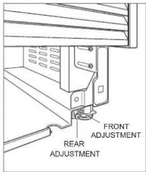
Leveling
Alignment
ANCHORING
Adjust the depth of the unit to fit flush with the surrounding cabinetry. Once aligned, verify the door/drawers open properly, then install the #8 x 1/2" flat-decorative head screws in each side trim.
WARNING
To avoid a hazard due to instability of the appliance, it must be fixed in accordance with the instructions.
Anchoring
Water Line
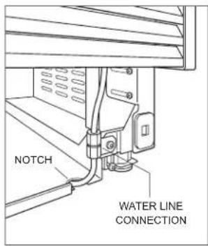
Approximately 3' (9 m) of 1/4" plastic tubing is connected to the unit with a preassembled 1/4" compression connection under the unit. The water line fitting connection kit, provided with the unit, contains a 1/4" compression union fitting for connection to the household water line.
Purge the water line prior to final connection to the unit. This will remove any debris that may be present in the tubing from installing the new water line. Connect the plastic tubing from the unit to the house water supply line with the fitting connection kit provided. Check all water line fittings for leaks.
Locate the water line in the notch as shown in the illustration below.
IMPORTANT NOTE: If a reverse osmosis system is used, it is recommended the water filtration system be bypassed by removing the filter.
IMPORTANT NOTE: Water lines cannot be exposed to freezing temperatures.
WARNING
Connect to potable water supply only.
Water line
Stainless Steel Panels
The outdoor model requires the use of Sub-Zero stainless steel outdoor accessory panels.
The thickness of indoor stainless steel panels is 34 " (19) and outdoor stainless steel panels is 112 " (38). The depth of each designer model is 24" (610). Allow for panel thickness when planning the finished opening depth.
Reveals of 18 " (3) are typical, however, the reveal between the upper and lower outdoor stainless steel panels is 14 " (6) to accommodate the lock.
Custom Panels
For designer models, custom door/drawer panels and handle hardware must be installed.
The thickness of the custom panel can vary. A minimum 58 " (16) thick panel is required, but the thickness can be increased provided it does not exceed the maximum panel weight indicated in the chart below. The depth of each designer model is 24" (610). Allow for panel thickness when planning the finished opening depth.
PANEL REQUIREMENTS
| WEIGHT PER PANEL MAX18" Column 45 lb (20 kg)24" Column 60 lb (27 kg)30" Column 75 lb (34 kg)36" Column 75 lb (34 kg) |
| WEIGHT PER PANEL MAX30" Tall (door) 50 lb (22 kg)36" Tall (door) 60 lb (27 kg)Drawer 15 lb (7 kg) |
| PANEL THICKNESS MINAll Panels 58 " (16) |
Reveals between panels can vary, 18 " (3) reveals are typical.
CAUTION
When installing a panel thicker than 1" (25), the 90° door stop may be required to prevent damage to the unit and adjacent cabinetry.
CAUTION
As reveals between cabinetry and the unit decrease, severe finger pinching can occur while the door is closing.
Finish all sides of the custom panels. They will be visible when the door/drawer is open.
D-style handles are recommended. Locate the door handle near the edge of the panel opposite the hinge and centered top to bottom. Locate the drawer handles near the top edge of each panel. Stainless steel tubular and pro handles are available through an authorized Sub-Zero dealer.
Custom Panels
DOOR PANEL HEIGHT
The height of the custom door panel can extend beyond the typical panel height, provided it does not exceed the weight limit. Refer to the illustration below.
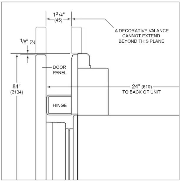
Upper valance (side view)
TOE KICK CLEARANCE (EXCLUDES OUTDOOR MODEL)
The height of the toe kick area can extend beyond the typical toe kick height, provided it does not exceed the dimensions in the illustration below. Toe kick heights from 2" (51) to 37/8" (98) require a reduced toe kick accessory available through an authorized Sub-Zero dealer. For questions regarding the installation, call Sub-Zero Customer Care at 800-222-7820.
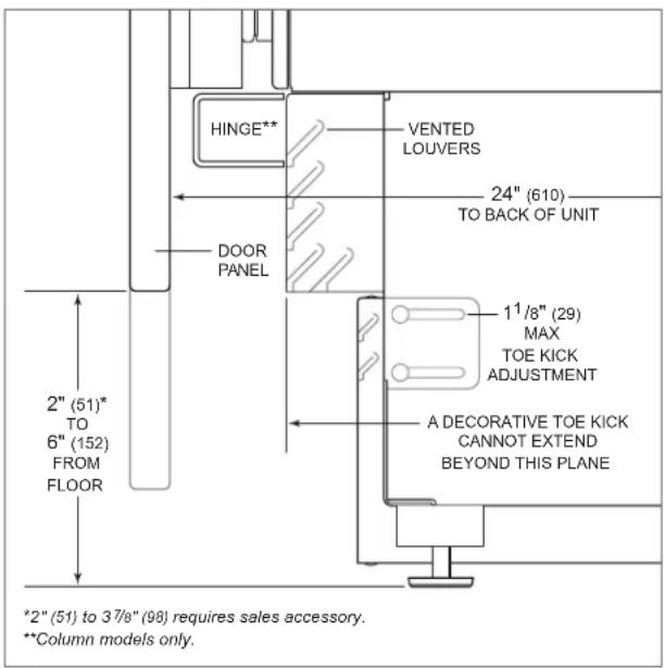
Toe kick (side view)
Panel Installation
DOOR PANEL INSTALLATION
Typical panel dimensions are based on an 84" (2134) finished height with 18 " (3) reveals. Placement of the template must be adjusted for panels exceeding the typical dimensions.
For tall models, the door panel should be installed first, followed by the upper, then lower drawer panel.
Place the panel face down on a protected work surface. Position the template flush with the top and sides of the panel. Verify the correct side of the template is being used, then mark and drill holes. Refer to the illustration below.
For tall models, align the notch in the template with the bottom of the door panel, then mark and drill holes. Refer to the illustration below.
Use a Torx drive to partially insert a #8 x 1/2" screw into the second hole from the top on each side of the panel. The screws should be approximately 3/16" (4) proud of the panel and will support the weight of the panel during installation.
Align the support screws on the back of the panel with the slotted holes on both door mounting brackets. Refer to the illustration below. Opening the door slightly may help with alignment. Once the panel is supported by the screws, partially insert a #8 x 1/2" screw into the second hole from the bottom on each side of the panel, but do not tighten.
CAUTION
As reveals between cabinetry and the unit decrease, severe finger pinching can occur while the door is closing.
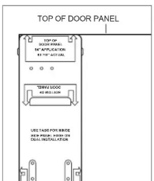
Door panel template—top
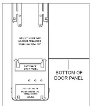
Door panel template—bottom (tall models only)
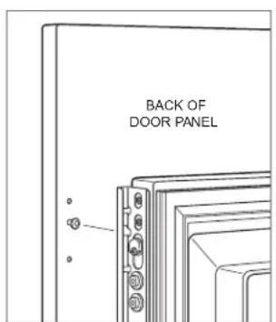
Door panel mounting
Panel Installation
DRAWER PANEL INSTALLATION
Place the panel face down on a protected work surface. Position the template flush with the top and sides of the panel. Verify the correct side of the template is being used, then mark and drill holes. Refer to the illustration below.
Use a Torx drive to partially insert a #8 x 1/2" screw into the second hole from the top on each side of the panel. The screws should be approximately 3/16" (4) proud of the panel and will support the weight of the panel during installation.
Align the support screws on the back of the panel with the slotted holes on both drawer mounting brackets. Refer to the illustration below. Opening the drawer slightly may help with alignment. Once the panel is supported by the screws, partially insert a #8 x 1/2" screw into the second hole from the bottom on each side of the panel, but do not tighten.
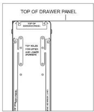
Drawer panel template—top
Drawer panel mounting
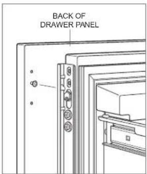
PANEL ADJUSTMENT
Close the door/drawers. Now, adjustments can be made to align the panels and reveals.
For side-to-side adjustment, move the panel side to side, then install and tighten all mounting screws.
For up-and-down and in-and-out adjustments, slightly loosen the bracket screws. Depending on the level of adjustment required, it may be helpful to loosen all of the bracket screws which will allow for maximum adjustment. Once the bracket screws are loosened, use a wrench to rotate the cams to make adjustments. After the adjustments have been made, tighten all bracket screws. Refer to the illustrations below.
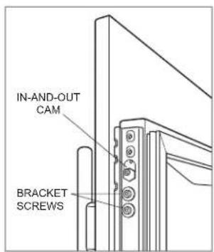
In-and-out adjustment
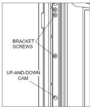
Up-and-down adjustment
Completion
DOOR TRIM INSTALLATION
After the panels have been adjusted, install the decorative side trim to the door/drawers. To install, start at the top and align the trim with the front and rear flanges on the bracket, then snap into place by pushing the trim toward the back of the panel. Once the top is secure, continue the installation downward until the remaining trim is completely secure. Refer to the illustrations below.
Door side trim
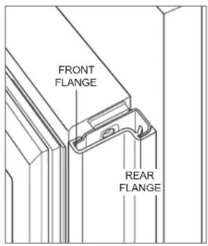
Bracket flanges
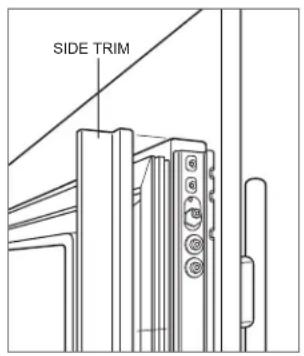
SIDE TRIM INSTALLATION
Install the decorative trim strip to the handle side of tall and column models. The side trim snaps over the bracket attached to the handle side of the unit. Refer to the illustration below.
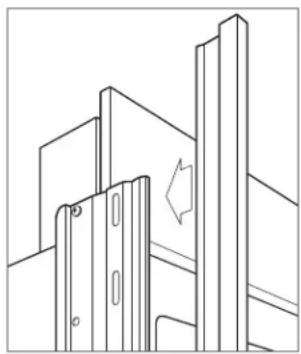
natural_image
Pure technical line drawing of a mechanical assembly without any text, numbers, or symbolsSide trim
Completion
KICKPLATE INSTALLATION
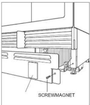
Position the kickplate and install using the two mounting screws. Refer to the illustration below. The kickplate must be removable for service. The floor cannot interfere with removal.
For indoor models, a maximum 6" (152) decorative kickplate can be attached to the factory-installed kickplate. The two rows of vented louvers can be covered if the door panel is a minimum 4" (102) from the finished floor. A decorative kickplate cannot be attached to the outdoor model.
To install a decorative kickplate, remove the paper backing from the magnets and attach the decorative kickplate to the magnets. The magnets allow the decorative kickplate to be removed if necessary.
Turn power on by touching "power" on the control panel.
Kickplate installation
Completion
90° DOOR STOP
A 105° door stop is built into the hinges of tall and column models. To limit the door swing to 90°, open the door slightly less than 90°, then use a standard screwdriver blade to remove the existing clips from each hinge. Locate the 90° clips from inside the plastic bag containing the product literature, then insert the 90° clips onto each hinge. Refer to the illustration below.
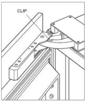
90° door stop
WATER FILTER BYPASS
If the water filtration system will not be used, it can be placed in water filter bypass mode by removing the water filter. Follow these steps to remove the water filter:
1 Pull out on the bottom edge of the access door and tilt upward.
2 To remove the filter, rotate counterclockwise one-quarter turn, then pull out. Refer to the illustration below.
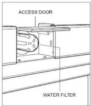
Water filter
Completion
WARNING
Follow all city and state laws when storing, recycling, or discarding unused refrigerators and freezers.
Sub-Zero, Sub-Zero & Design, Sub-Zero & Snowflake Design, Dual Refrigeration, The Living Kitchen, Great American Kitchens The Fine Art of Kitchen Design, Wolf, Wolf & Design, Wolf Gourmet, W & Design, red colored knobs, Cove, and Cove & Design are registered trademarks and service marks of Sub-Zero Group, Inc. and its subsidiaries. All other trademarks are property of their respective owners in the United States and other countries.
Contenido
natural_image
Pure architectural line drawing of a building facade with vertical supports and a window (no text or symbols)Ribete lateral
Finalización
natural_image
Pure technical line drawing of a mechanical bracket assembly without any text, numbers, or symbolsGarniture latérale
Achèvement
INSTALLATION DE LA PLAQUE DE PROTECTION
Installation de la plaque de protection
Achèvement
BUTÉE DE PORTE DE 90°
- Designer Series Refrigeration
- Installation Guide
- Contents
- Important Note
- CAUTION
- WARNING
- Product Information
- Opening Dimensions
- COLUMN / TALL WH
- DRAWER WH
- DUAL INSTALLATION
- Electrical Requirements
- Plumbing Requirements
- Preparation
- Anti-Tip Bracket
- WOOD FLOOR APPLICATION
- CONCRETE FLOOR APPLICATION
- CONCRETE WEDGE ANCHOR INSTALLATION
- Placement
- Alignment
- LEVELING
- ANCHORING
- Water Line
- Stainless Steel Panels
- Custom Panels
- DOOR PANEL HEIGHT
- TOE KICK CLEARANCE (EXCLUDES OUTDOOR MODEL)
- Panel Installation
- DOOR PANEL INSTALLATION
- DRAWER PANEL INSTALLATION
- PANEL ADJUSTMENT
- Completion
- DOOR TRIM INSTALLATION
- SIDE TRIM INSTALLATION
- KICKPLATE INSTALLATION
- 90° DOOR STOP
- WATER FILTER BYPASS
- Contenido
- Finalización
- Achèvement
- INSTALLATION DE LA PLAQUE DE PROTECTION
- BUTÉE DE PORTE DE 90°
Brand : Sub-Zero
Model : DET3650RIDR
Category : Refrigerator