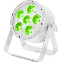
BAC803 - Effect machine BeamZ - Free user manual and instructions
Find the device manual for free BAC803 BeamZ in PDF.


User questions about BAC803 BeamZ
0 question about this device. Answer the ones you know or ask your own.
Ask a new question about this device
Download the instructions for your Effect machine in PDF format for free! Find your manual BAC803 - BeamZ and take your electronic device back in hand. On this page are published all the documents necessary for the use of your device. BAC803 by BeamZ.
USER MANUAL BAC803 BeamZ
150.802_150.803_150.822 V1.1
BAC322 & 332
USER MANUAL
INDEX
ENGLISH
SAFETY INSTRUCTIONS....3
UNPACKING INSTRUCTION 4
POWERSUPPLY 4
RIGGING 4
DMX512 CONTROL 5
RDM CONTROL....5
REMOTE CONTROLLER....5
MAINTENANCE 6
TROUBLE SHOOTING 7
NEDERLANDS
VEILIGHEIDSINSTRUCTIES 8
UITPAKKEN....9
AANSLUITSPANNING 9
RIGGING....9
DMX BEDIENING....10
RDM BEDIENING....10
AFSTANDSBEDIENING....10
ONDERHOUD....11
PROBLEMEN OPLOSSEN 12
DEUTSCH
WARNING! Before carrying out any operations with the unit, carefully read this instruction manual and keep it with care for future reference. It contains important information about the installation, usage and maintenance of the unit.
• Unpack and check carefully that there is no transportation damage before using the unit
- Please read these instructions carefully and follow the instructions.
- Observe all safety warnings. Never remove safety warnings or other information from the equipment.
- Be sure that no ventilation slots are blocked; otherwise the unit will overheated.

WARNING! Before connecting the equipment to the power outlet, first verify that the mains voltage and frequency match the values specified on the equipment. If the equipment has a voltage selection switch, connect the equipment to the power outlet only if the equipment values and the mains power values match. If the included power cord or power adapter does not fit in your wall outlet, contact your electrician.
• After connecting the unit, check all cables in order to prevent damage or accidents, e.g., due to tripping hazards.
• Make sure that the power cord is never crimped or damaged. Check the unit and the power cord from time to time.
- Always disconnect power from the mains, when unit is not used or before cleaning! Only handle the power cord by the plug. Never pull out the plug by tugging the power cord.
• Unplug the power cord and power adapter from the power outlet if there is a risk of a lightning strike or before extended periods of disuse.
- Do not switch the unit on and off in short intervals.
- Do not connect the unit to a dimmerpack.
• Install the unit in a well ventilated place.
- Never place any material over the lens.
- Never let the sunlight lights directly to the front lens, even when the unit is not working.
• Always allow free air space of at least 50 cm around the unit for ventilation.
• Make sure that the area below the installation place is blocked when rigging, derigging or servicing the unit.
- For mounting height >100 cm, always fix the unit with an appropriate safety-rope. Fix the safety-rope at the correct fixation points only. The safety-rope must never be fixed at the transport handles!
- Never look directly at the light beam. Please note that fast changes in lighting, e.g. flashing light, may trigger epileptic seizures in photosensitive persons or persons with epilepsy.
- This unit is not designed for permanent operation. Consistent operation breaks will ensure that the unit will serve you for a long time without defects.

WARNING! If the power cord of the unit is equipped with an earthing contact, then it must be connected to an outlet with a protective ground. Never deactivate the protective ground of a power cord.
• Make sure that the unit is not exposed to extreme heat, moisture or dust.
- Clean the unit using a dry cloth.
- Do not touch the unit bare-handed during its operation (housing becomes very hot). Allow the unit to cool for at least 5 minutes before handling.
- This unit is designed exclusively for indoor use, do not use this equipment in the immediate vicinity of fluid (does not apply to special outdoor equipment - in this case, observe the special instructions noted below). Do not expose this unit to flammable materials, fluids or gases.
- If the unit has been exposed to drastic temperature fluctuation (e.g. after transportation), do not switch it on immediately. The arising condensation water might damage your unit. Leave the unit switched off until it has reached room temperature.
- Never attempt to bypass the thermostatic switch or fuses.
- Do not dismantle or modify the unit.
- For replacement use fuses/bulb of same type and rating only.
• Repairs, servicing and electric connection must be carried out by a qualified technician.
- The ambient temperature must always be between -5^ and +45^ .
- If this unit is operated in any other way, than the one described in this manual, the product may suffer damages and the warranty becomes void.
- Plastic bags must be kept out of reach of children.
- Unit must be installed out of the reach of children. Never leave the unit running unattended.

This symbol on the product or on its packaging indicates that this product shall not be treated as household waste. Instead it shall be handed over to the applicable collection point for the recycling of electrical and electronic equipment.
By ensuring this product is disposed of correctly, you will help prevent potential negative consequences for the environment and human health, which could otherwise be caused by inappropriate waste handling of this product. The recycling of materials will help to conserve natural resources. For more detailed information about recycling of this product, please contact your local Civic Office, your household waste disposal service or the shop where you purchased the product.
UNPACKING INSTRUCTION

CAUTION! Immediately upon receiving the product, carefully unpack the carton, check the contents to ensure that all parts are present, and have been received in good condition. Notify the shipper immediately and retain packing material for inspection if any parts appear damage from or the package itself shows signs of mishandling. Save the package and all packing materials. In the event that the product must be returned to ry, it is important that the product be returned in the original factory box and packing.
If the unit has been exposed to drastic temperature fluctuation (e.g. after transportation), do not switch it on immediately. The arising condensation water might damage your unit. Leave the unit switched off until it has reached room temperature.
POWERSUPPLY
On the label on the backside of the unit is indicated on this type of power supply must be connected. Check that the mains voltage corresponds to this, all other voltages than specified, the light effect can be irreparably damaged. The product must also be directly connected to the mains and may be used. No dimmer or adjustable power supply.

WARNING! Always connect the unit to a protected circuit (circuit breaker or fuse). Make sure the unit has an appropriate electrical ground to avoid the risk of electrocution or fire.
RIGGING
The unit may be set up on a stable and even surface. By means of the fixing facilities of the baseplate, the unit can also be mounted upside down to a truss, see below picture. For fixing, certified clamps with correct save working load are required. According to the figure, the quick lock bolts of the omega brackets are placed into the openings provided in the base plate and turned clockwise until they lock (to the stop). The mounting place must be of sufficient stability and be able to support a weight of 10 times of the unit's weight. Secure the unit with a safety cable so that it cannot fall down.
When carrying out any installation, always comply European and national guidelines concerning rigging, truss and all other safety issues. Always let the installation checked out by an authorized dealer!

natural_image
Technical line drawing of four different types of spotlights mounted on a vertical structure (no text or symbols present)DMX512 CONTROL
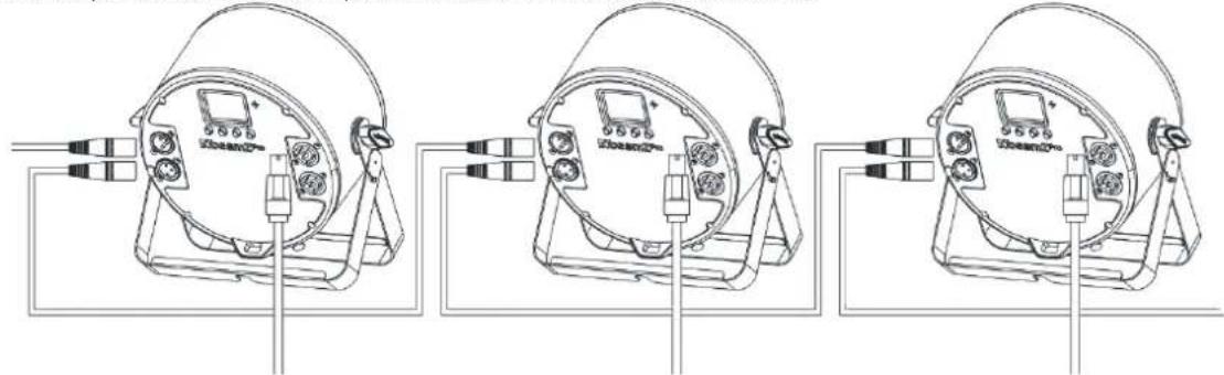
If you are using a standard DMX controller, you can connect the DMX output of the controller directly to the DMX input of the first unit in a DMX chain. Always connect the output of one unit with the input of the next unit until all units are connected.
natural_image
Three identical line drawings of a dual-camera display unit with connectors and wiring, no text or symbols present.
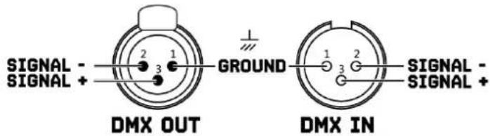
CAUTION! At the last unit, you must close the DMX line with a terminating resistor. Take an XLR connector and solder a 120 Ohm resistor between signal (-) and signal (+) and connect it to the DMX output of the last unit in the line.
text_image
SIGNAL - SIGNAL + DMX OUT GROUND 1 2 3 DMX IN 1 2 3 SIGNAL - SIGNAL + -
text_image
1 2 3 120 OHM TERMINATORRDM CONTROL
This unit can communicate using RDM (Remote Device Management) via DMX512. RDM is a bi-directional communication protocol for use in DMX512 control systems, it is the open standard for DMX512 configuration and status monitoring.
The RDM protocol allows data packets to be inserted into a DMX512 line without affecting the existing non-RDM equipment. The system allows a controller or special RDM controller to send and receive commands from specific fixtures.
The RDM function allows you, for example to remotely set the DMX start address of your fixtures. This is especially useful when the fixture is installed in an inaccessible location. Each unit has an RDM UID (unique identification number).
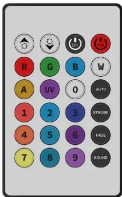
REMOTE CONTROLLER
POWER
Press <OFF existing modes. Press for power on.
AUTO MODE
Automatic mode will enable you to run the automatic programs on the product.
To turn on Automatic mode:
-
Press
emote controller. -
Press (AUTO) off auto mode.
STROBE MODE
To adjust the strobe speed of the automatic program and the sound active program.
-
Press
mote controller. -
Press
stop this function.
FADE/UNIT MODE
To adjust the FADE speed of the automatic program, the sound active program and the manual mode.
-
Press (FADE) remote controller.
-
Press
stop this function.
SOUND MODE
To enable /disable the sound mode.
-
Press SOUND remote controller.
-
Press against stop this function.
MANUAL MODE
-
Press one of the colours on the remote controller.
-
Press again to close your colour.
-
Press UP to either DOWN or decrease the percentage of each colour.
text_image
R G B W A UV 0 AUTO 1 2 3 STROBE 4 5 6 FADE 7 8 9 SOUND
CAUTION! The remote control is supplied with a battery inserted. An insulating foil between the battery and the battery contacts prevents the battery from being discharged during storage. Prior to the first operation remove the foil from the battery support on the rear side of the remote control. Otherwise operation of the remote control is not possible.
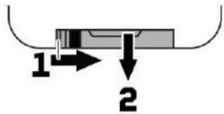
If the range of the remote control decreases, replace the battery. For this purpose, on the rear side of the remote control press the small bar with the groove to the right (1) and at the same time remove the battery support (2). For operation, one 3 V button cell type CR 2025 is required. When inserting, pay attention that the positive pole of the button cell shows upwards in the support.
text_image
1 2MAINTENANCE
This unit is virtually maintenance-free, but you should check the unit regularly for mechanical and electrical aspects.
Assess the operating environment and establish an inspection and cleaning schedule that follows the guidelines below:
- Disconnect the unit from the power supply and allow it to cool completely before inspecting and cleaning.
- Check that the screws and bolts used to install the unit are securely tightened and free from corrosion.
- Check the housing, fixing points and installation points, they must not show any signs of deformation, wear or fatigue.
- Check the mechanically moving parts, these must not show any signs of wear or fatigue.
- Check the electrical power and signal cables, they must not show any damage or fatigue.
- Do not use solvents, abrasives or other aggressive products to clean the unit.
- Wipe the unit and clean the glass plate with a soft, clean, lint-free cloth moistened with a weak cleaning solution. Place the solution on the cloth and not on the surface to be cleaned. Avoid rubbing glass surfaces.
- Dry the unit, connectors and contacts with a soft, clean, lint-free cloth or low-pressure compressed air before re-powering the unit.
TROUBLE SHOOTING
The checklist below may help you troubleshoot in the unlikely event that a problem occurs while using the product:
| SYMPTOM | POSSIBLE CAUSE | SUGGESTED ACTION |
| No response from unit. | No power to unit. | Check that power is turned on.Check cables and connections.Contact Beamz support or Beamz authorized service partner. Do not remove base or yoke covers. Do not attempt to replace a fuse or carry out any repairs or service that are not described in this User Manual unless you have both authorization from Beamz support or Beamz authorized service partner. |
| Internal fault. | ||
| Unit resets correctly but does not respond (or does not respond correctly) to the controller. | The controller is not connected. | Connect controller. |
| Bad DMX-line. | Inspect connections and cables. Correct poor connections. Repair or replace damaged cables. | |
| DMX-line has no end resistance. | Insert DMX terminator plug in DMX output socket of last unit on DMX-line. | |
| Incorrect unit addressing. | Check unit address and DMX mode settings. | |
| A unit is defective and is disturbing data transmission on the DMX-line. | Unplug DMX IN and OUT connectors and connect them directly together to bypass one unit at a time until normal operation is regained. Have defective unit serviced by an authorized technician. | |
| Pin 2 and 3 are reversed in XLR connection. | Inspect connections and cables. Install a phase-reversing cable between the units or swap pin 2 and 3 in the unit, that behaves erratically. | |
| Error after unit reset. | Effect requires mechanical adjustment. | Check unit's software version and error messages for more information. Contact Beamz support or Beamz authorized service partner. |
| Light output cuts out intermittently. | Unit too hot. | Allow unit to cool. Reduce ambient temperature. Ensure free airflow around unit. Clean unit if necessary. |
| LEDs damaged. | Disconnect unit and contact Beamz support or Beamz authorized service partner. | |
| The power supply settings do not match local AC voltage and frequency. | Disconnect unit. Check settings and correct if necessary. |
VEILIGHEIDSINSTRUCTIES

natural_image
Technical line drawing of four different types of spotlights mounted on a vertical structure (no text or symbols present)DMX BEDIENING
natural_image
Three identical line drawings of a dual-camera display unit with connectors and wiring, no text or symbols present.
natural_image
Technical line drawing of four different types of spotlights mounted on a vertical structure (no text or symbols present)DMX BEDIENUNG
natural_image
Three identical line drawings of a spherical lamp with attached connectors and indicator lights (no text or symbols)
natural_image
Technical line drawing of four different types of spotlights mounted on a vertical structure (no text or symbols present)CONTROL DMX512
natural_image
Three identical line drawings of a spherical lamp with attached connectors and indicator lights (no text or symbols)
natural_image
Technical line drawing of four different types of spotlights mounted on a metal frame structure (no text or symbols present)ESTION DMX512
natural_image
Three identical line drawings of a dual-camera projector with attached cable, shown from different angles (no text or symbols)
natural_image
Technical line drawing of four different types of spotlights mounted on a vertical ladder, with no visible text or symbols.KONTROLA DMX512
natural_image
Three identical line drawings of a dual-camera projector with labeled ports and wiring (no text or symbols)
| MENU | DESCRIPTION | ||
| ADDRESS | 001-512 | DMX address setting | |
| CHANNEL | 6 channels | DMX channel mode | |
| 8 channels | |||
| 10 channels | |||
| 11 channels | |||
| DIM CURVE | Dim curve 1 | Select dimmer curve | |
| Dim curve 2 | |||
| Dim curve 3 | |||
| Dim curve 4 | |||
| DMX STATE | Blackout/Hold | Select DMX status when signal lost. | |
| STATIC COLOUR | 1-32 | Static colour | |
| JUMP MODE | 1-9 | Speed from slow to fast | |
| FADE MODE | 1-9 | Speed from slow to fast | |
| PULSE MODE | 1-9 | Speed from slow to fast | |
| SOUND MODE | Sub Mode | 1-4 | Sound mode 1-4 |
| Sensitivity | 1-9 | Adjust sensitivity | |
| MANUAL MODE | Red | 000-255 | Dimmer Red |
| Green | 000-255 | Dimmer Green | |
| Blue | 000-255 | Dimmer Blue | |
| Amber | 000-255 | Dimmer Amber | |
| Lime | 000-255 | Dimmer Lime | |
| Cyan | 000-255 | Dimmer Cyan | |
| Strobe | 000-009 | Speed from slow to fast | |
| SET UP | Key Lock | OFF/ON | Enable/disable button lock function |
| Remote | OFF/ON | Enable/disable infrared remote function | |
| Display | 10s/20s/30S/Always ON | Display standby time | |
| Reset | YES/NO | Reset system | |
| INFORMATION | Model | BAC series | Product model |
| Colour | RGBXXX | LED mix colour | |
| Software | Vxxx | Software version | |
| Hardware | QY-XXX | Hardware version | |
| Work Time | xxxxxH | Current running time | |
| Total Time | xxxxxH | Total running time | |
DMX CHANNELS
6 CHANNELS
| CHANNEL | FUNCTION | VALUE | DESCRIPTION |
| 1 | RED | 000-255 | Dimmer Red 0-100% |
| 2 | GREEN | 000-255 | Dimmer Green 0-100% |
| 3 | BLUE | 000-255 | Dimmer Blue 0-100% |
| 4 | AMBER | 000-255 | Dimmer Amber 0-100% |
| 5 | LIME | 000-255 | Dimmer Lime 0-100% |
| 6 | CYAN | 000-255 | Dimmer Cyan 0-100% |
8 CHANNELS
| CHANNEL | FUNCTION | VALUE | DESCRIPTION |
| 1 | DIMMER | 000-255 | Master Dimmer 0-100% |
| 2 | RED | 000-255 | Dimmer Red 0-100% |
| 3 | GREEN | 000-255 | Dimmer Green 0-100% |
| 4 | BLUE | 000-255 | Dimmer Blue 0-100% |
| 5 | AMBER | 000-255 | Dimmer Amber 0-100% |
| 6 | LIME | 000-255 | Dimmer Lime 0-100% |
| 7 | CYAN | 000-255 | Dimmer Cyan 0-100% |
| 8 | STROBE | 000-009 | No function |
| 010-255 | Strobe from slow to fast |
10 CHANNELS
| CHANNEL | FUNCTION | VALUE | DESCRIPTION |
| 1 | DIMMER | 000-255 | Master Dimmer 0-100% |
| 2 | RED | 000-255 | Dimmer Red 0-100% |
| 3 | GREEN | 000-255 | Dimmer Green 0-100% |
| 4 | BLUE | 000-255 | Dimmer Blue 0-100% |
| 5 | AMBER | 000-255 | Dimmer Amber 0-100% |
| 6 | LIME | 000-255 | Dimmer Lime 0-100% |
| 7 | CYAN | 000-255 | Dimmer Cyan 0-100% |
| 8 | STROBE | 000-009 | No function |
| 010-255 | Strobe from slow to fast | ||
| 9 | MODE | 000-020 | No function |
| 021-050 | Static colour (colour is controlled by CH10, please refer to below table) | ||
| 051-080 | Jump mode (Speed controlled by CH10) | ||
| 081-110 | Fade mode (Speed controlled by CH10) | ||
| 111-140 | Pulse mode (Speed controlled by CH10) | ||
| 141-170 | Sound mode 1 (Sensitivity controlled by CH10) | ||
| 171-200 | Sound mode 2 (Sensitivity controlled by CH10) | ||
| 201-230 | Sound mode 3 (Sensitivity controlled by CH10) | ||
| 231-255 | Sound mode 4 (Sensitivity controlled by CH10) | ||
| 10 | CONTROL MODE | 000-255 | Speed from slow to fast (CH9=051-140) |
| 000-255 | Static colour (CH9=021-050, please refer to below table for details) | ||
| 000-255 | Sensitivity (CH9=141-255) |
11 CHANNELS
| CHANNEL | FUNCTION | VALUE | DESCRIPTION |
| 1 | DIMMER | 000-255 | Master Dimmer 0-100% |
| 2 | RED | 000-255 | Dimmer Red 0-100% |
| 3 | GREEN | 000-255 | Dimmer Green 0-100% |
| 4 | BLUE | 000-255 | Dimmer Blue 0-100% |
| 5 | AMBER | 000-255 | Dimmer Amber 0-100% |
| 6 | LIME | 000-255 | Dimmer Lime 0-100% |
| 7 | CYAN | 000-255 | Dimmer Cyan 0-100% |
| 8 | STROBE | 000-009 | No function |
| 010-255 | Strobe from slow to fast | ||
| 9 | MODE | 000-020 | No function |
| 021-050 | Static colour (colour is controlled by CH10, please refer to below table) | ||
| 051-080 | Jump mode (Speed controlled by CH10) | ||
| 081-110 | Fade mode (Speed controlled by CH10) | ||
| 111-140 | Pulse mode (Speed controlled by CH10) | ||
| 141-170 | Sound mode 1 (Sensitivity controlled by CH10) | ||
| 171-200 | Sound mode 2 (Sensitivity controlled by CH10) | ||
| 201-230 | Sound mode 3 (Sensitivity controlled by CH10) | ||
| 231-255 | Sound mode 4 (Sensitivity controlled by CH10) | ||
| 10 | CONTROL MODE | 000-255 | Speed from slow to fast (CH9=051-140) |
| 000-255 | Static colour (CH9=021-050, please refer to below table for details) | ||
| 000-255 | Sensitivity (CH9=141-255) | ||
| 11 | DIMMING CURVE | 000-063 | Dimmer curve 1 |
| 064-127 | Dimmer curve 2 | ||
| 128-191 | Dimmer curve 3 | ||
| 192-255 | Dimmer curve 4 |
STATIC COLOR TABLE:
| VALUE | DESCRIPTION | VALUE | DESCRIPTION |
| 000-007 | Static colour 1 | 128-135 | Static colour 17 |
| 008-015 | Static colour 2 | 136-143 | Static colour 18 |
| 016-023 | Static colour 3 | 144-151 | Static colour 19 |
| 024-031 | Static colour 4 | 152-159 | Static colour 20 |
| 032-039 | Static colour 5 | 160-167 | Static colour 21 |
| 040-047 | Static colour 6 | 168-175 | Static colour 22 |
| 048-055 | Static colour 7 | 176-183 | Static colour 23 |
| 056-063 | Static colour 8 | 184-191 | Static colour 24 |
| 064-071 | Static colour 9 | 192-199 | Static colour 25 |
| 072-079 | Static colour 10 | 200-207 | Static colour 26 |
| 080-087 | Static colour 11 | 208-215 | Static colour 27 |
| 088-095 | Static colour 12 | 216-223 | Static colour 28 |
| 096-103 | Static colour 13 | 224-231 | Static colour 29 |
| 104-111 | Static colour 14 | 232-239 | Static colour 30 |
| 112-119 | Static colour 15 | 240-247 | Static colour 31 |
| 120-127 | Static colour 16 | 248-255 | Static colour 32 |


The products referred to in this manual conform to the European Community Directives to which they are subject:
European Union
Tronios B.V.,
7602KR Almelo, The Netherlands
2014/35/EU
2014/30/EU
2011/65/EC

United Kingdom
Tronios Ltd.,
130 Harley Street,
London W1G 7JU, United Kingdom
S.I. 2016:1101
S.I. 2016:1091
S.I. 2012:3032

BEAMZ
offers a wide range of high performance lighting equipment and related accessories for the rental, entertainment and architectural lighting markets. BeamZ Pro stands for performance, innovation and value pricing!


