
WSTT20V - Electric lawn mower WESTINGHOUSE - Free user manual and instructions
Find the device manual for free WSTT20V WESTINGHOUSE in PDF.


| Product Type | Cordless String Trimmer (Electric Lawn Mower) |
| Brand | Westinghouse |
| Model | WSTT20V |
| Power Source | 20V DC Lithium-Ion Battery |
| Compatible Battery | W20V2AH, W20V4AH, W20V5AH |
| Compatible Charger | W20V2AMP, W20V2DP |
| No Load Speed | 8000 RPM |
| Cutting Diameter | 12 in (300 mm) |
| Line Diameter | 0.065 in or 0.080 in (round or twisted) |
| Line Advance | Automatic (by stop/start) and Manual |
| Edging Function | Yes (180° pivoting tube) |
| Auxiliary Handle | Yes, adjustable |
| Safety Switch | Lock button + trigger |
| Blade Guard | Yes |
| Operating Temperature | -10°C to 40°C (14°F to 104°F) |
| Weight (approx.) | 2.5 kg (5.5 lb) |
| Warranty | See manual (registration required) |
| Maintenance | Clean after use, check for loose parts |
| Replacement Parts | Spool, line, guard, auxiliary handle |
Frequently Asked Questions - WSTT20V WESTINGHOUSE
User questions about WSTT20V WESTINGHOUSE
0 question about this device. Answer the ones you know or ask your own.
Ask a new question about this device
Download the instructions for your Electric lawn mower in PDF format for free! Find your manual WSTT20V - WESTINGHOUSE and take your electronic device back in hand. On this page are published all the documents necessary for the use of your device. WSTT20V by WESTINGHOUSE.
USER MANUAL WSTT20V WESTINGHOUSE
natural_image
Blue circular icon with a white crown symbol (no text or numbers)User Manual
WST 20V / WSTT 20V
12 in. Cordless String Trimmer
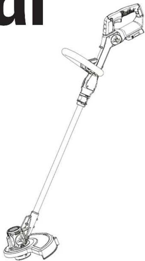
natural_image
Line drawing of a handheld device with lever and base mount (no text or symbols)Introduction 2-3
Safety 4-6
Components....7
Assembly 8-9
Operation 10-11
Maintenance....12
Troubleshooting....13
Parts Page....14
Service Hot Line/Company Address......Back Page
INTRODUCTION

WARNING
Operating, servicing, and maintaining this equipment may expose you to chemicals which are known to the State of California to cause cancer and birth defects or other reproductive harm. To minimize exposure, wear gloves or wash your hands frequently when servicing this equipment. For more information go to www.P65warnings.ca.gov.
DISCLAIMERS
All information, illustrations, and specifications in this manual were in effect at the time of publishing. The illustrations used in this manual are intended as representative reference views only. We reserve the right to make any specification or design change without notice.
ALL RIGHTS RESERVED
All rights reserved. No reproduction allowed in any form without written permission from Westinghouse Outdoor Power Equipment.


DANGER
Read this manual before using or performing maintenance on this product. Failure to follow the instructions and safety precautions in this manual can result in serious injury or death.
UPDATES
The latest User Manual for your Westinghouse products can be found under our support tab: westinghouse.com/pages/manuals
Or scan the following QR code with your smartphone camera to be directed to the link.
PRODUCT REGISTRATION
For trouble-free warranty coverage, it is important to register your Westinghouse product.
Register by:
- Completing and mailing the product registration card included in the carton.
- Registering your product online at: westinghouse.com/register
- Scanning the above QR code with your smartphone camera to be directed to the mobile registration link.
For Your Records
Date of Purchase: ____
Model Number:
Serial Number: ____
Place of Purchase: ____


- Sending the following product information to:
Westinghouse Outdoor Power
Warranty registration
777 Manor Park Drive
Columbus, OH 43228
IMPORTANT: Keep your purchase receipt for trouble-free warranty coverage.
SPECIFICATIONS
DC Voltage 20 V
No Load Speed....8000 RPM
Cutting Diameter 12 in. (300 mm)
NOTICE This product is designed for optimal compatibility with the Westinghouse batteries and chargers listed below. Use with any other batteries or chargers not listed below may result in serious personal injury or death.
| Model Motor Westinghouse Battery | Pack Westinghouse Charger | ||
| WST 20V / WSTT 20V 20V DC | W20V2AHW20V4AHW20V5AH | W20V2AMPW20V2DP | |
NOTICE This product is designed and rated for continuous operation at ambient temperatures above 14irc F ( -10irc C). If needed, this product can be operated in extremely cold temperatures for short periods. If the product is exposed to temperatures, greater than or equal to 104irc F ( 40irc C) or less than or equal to 32irc F ( 0irc C) during storage, it should be brought back within the optimal temperature range 32-104irc F ( 0-40irc C) before operation.
NOTICE Thank you for choosing Westinghouse! PLEASE READ THIS MANUAL BEFORE RETURNING THIS PRODUCT FOR ANY REASON.
If you have a question or experience a problem with your Westinghouse purchase, call us at 1-855-944-3571 to speak with an agent.
RETAIN THIS MANUAL FOR FUTURE REFERENCE.
HAVE QUESTIONS? Email us at service@wpowereq.com or call 1-855-944-3571
SAFETY DEFINITIONS
The words DANGER, WARNING, CAUTION, and NOTICE are used throughout this manual to highlight important information. Be sure that the meanings of this safety information is known to all who operate, perform maintenance on, or are near the string trimmer.

This safety alert symbol appears with most safety statements. It means attention, become alert, safety is involved. Please read and abide by the message that follows the safety alerts symbol.
DANGER Indicates a hazardous situation which, if not avoided, will result in death or serious injury.
WARNING Indicates a hazardous situation which, if not avoided, could result in death or serious injury.
CAUTION Indicates a hazardous situation which, if not avoided, could result in minor or moderate injury.
NOTICE Indicates a situation which can cause damage to the string trimmer, personal property, and/or the environment, or cause the equipment to operate improperly.
NOTE: Indicates a procedure, practice or condition that should be followed for the string trimmer to function in the manner intended.
SAFETY SYMBOLS
Follow all safety information contained in this user manual as well as the information on the product labeling.
| SYMBOL | DESCRIPTION |
 | Safety Alert Symbol. Indicates a potential personal injury hazard. |
 | Read User Manual. To reduce the risk of injury, user must read and understand user manual before using this product. |
 | Keep all bystanders 50 ft. away. |
 | Always wear eye protection. Protective equipment such as a dust mask, non-skid safety shoes, hard hat or hearing protection used for appropriate conditions will reduce personal injuries. |
| [2WSZ] | Thrown objects can ricochet and result in personal injury or property damage. |
 | Wet Conditions Alert. Do not expose the battery pack, battery compartment, or electronic components to water or rain. |
 | WARNING - Disconnect battery before maintenance. |
General power tool safety warnings
The term “power tool” in the warnings refers to a mains-operated (corded) power tool or battery-operated (cordless) power tool.
WARNING
READ AND UNDERSTAND ALL IN-
STRUCTIONS. Failure to follow all instructions listed below and on the machine may result in electric shock, fire, and/or serious personal injury.
Save all warnings and instructions for future reference.
For safe operation, read and understand all instructions before using this product. Follow all safety instructions. Failure to follow all safety instructions listed can result in serious personal injury.
Work area safety
- Keep work area clean and well lit. Cluttered or dark areas invite accidents.
- Do not operate power tools in explosive atmospheres, such as in the presence of flammable liquids, gases or dust. Power tools create sparks which may ignite the dust or fumes.
- Keep children and bystanders away while operating a power tool. Distractions can cause you to lose control.
Electrical safety
- Power tool plugs must match the outlet. Never modify the plug in any way. Do not use any adapter plugs with earthed (grounded) power tools. Unmodified plugs and matching outlets will reduce risk of electric shock.
- Avoid body contact with earthed or grounded surfaces, such as pipes, radiators, ranges and refrigerators. There is an increased risk of electric shock if your body is earthed or grounded.
- Do not expose power tools to rain or wet conditions. Water entering a power tool will increase the risk of electric shock.
- Do not abuse the cord. Never use the cord for carrying, pulling or unplugging the power tool. Keep cord away from heat, oil, sharp edges or moving parts. Damaged or entangled cords increase the risk of electric shock.
- When operating a power tool outdoors, use an extension cord suitable for outdoor use. Use of a cord suitable for outdoor use reduces the risk of electric shock.
- If operating a power tool in a damp location is unavoidable, use a residual current device (RCD) protected supply. Use of an RCD reduces the risk of electric shock.
Personal safety
- Stay alert, watch what you are doing and use common sense when operating a power tool. Do not use a power tool while you are tired or under the influence of drugs, alcohol or medication. A moment of inattention while operating power tools may result in serious personal injury.
- Use personal protective equipment. Always wear eye protection. Protective equipment such as a dust mask, non-skid safety shoes, hard hat or hearing protection used for appropriate conditions will reduce personal injuries.
- Prevent unintentional starting. Ensure the switch is in the off-position before connecting to power source and/or battery
pack, picking up or carrying the tool. Carrying power tools with your finger on the switch or energising power tools that have the switch on invites accidents.
- Remove any adjusting key or wrench before turning the power tool on. A wrench or a key left attached to a rotating part of the power tool may result in personal injury.
- Do not overreach. Keep proper footing and balance at all times. This enables better control of the power tool in unexpected situations.
- Dress properly. Do not wear loose clothing or jewellery. Keep your hair and clothing away from moving parts. Loose clothes, jewellery or long hair can be caught in moving parts.
- If devices are provided for the connection of dust extraction and collection facilities, ensure these are connected and properly used. Use of dust collection can reduce dust-related hazards.
- Do not let familiarity gained from frequent use of tools allow you to become complacent and ignore tool safety principles. A careless action can cause severe injury within a fraction of a second.
Power tool use and care
- Do not force the power tool. Use the correct power tool for your application. The correct power tool will do the job better and safer at the rate for which it was designed.
- Do not use the power tool if the switch does not turn it on and off. Any power tool that cannot be controlled with the switch is dangerous and must be repaired.
- Disconnect the plug from the power source and/or remove the battery pack, if detachable, from the power tool before making any adjustments, changing accessories, or storing power tools. Such preventive safety measures reduce the risk of starting the power tool accidentally.
- Store idle power tools out of the reach of children and do not allow persons unfamiliar with the power tool or these instructions to operate the power tool. Power tools are dangerous in the hands of untrained users.
- Maintain power tools and accessories. Check for misalignment or binding of moving parts, breakage of parts and any other condition that may affect the power tool's operation. If damaged, have the power tool repaired before use. Many accidents are caused by poorly maintained power tools.
- Keep cutting tools sharp and clean. Properly maintained cutting tools with sharp cutting edges are less likely to bind and are easier to control.
- Use the power tool, accessories and tool bits etc. in accordance with these instructions, taking into account the working conditions and the work to be performed. Use of the power tool for operations different from those intended could result in a hazardous situation.
- Keep handles and grasping surfaces dry, clean and free from oil and grease. Slippery handles and grasping surfaces do not allow for safe handling and control of the tool in unexpected situations.
Battery tool use and care
- Recharge only with the charger specified by the manufacturer. A charger that is suitable for one type of battery pack may create a risk of fire when used with another battery pack.
- Use power tools only with specifically designated battery packs. Use of any other battery packs may create a risk of injury and fire.
- When battery pack is not in use, keep it away from other metal objects, like paper clips, coins, keys, nails, screws or other small metal objects, that can make a connection from one terminal to another. Shorting the battery terminals together may cause burns or a fire.
- Under abusive conditions, liquid may be ejected from the battery; avoid contact. If contact accidentally occurs, flush with water. If liquid contacts eyes, additionally seek medical help. Liquid ejected from the battery may cause irritation or burns.
- Do not use a battery pack or tool that is damaged or modified. Damaged or modified batteries may exhibit unpredictable behaviour resulting in fire, explosion or risk of injury.
- Do not expose a battery pack or tool to fire or excessive temperature. Exposure to fire or temperature above 130 °C may cause explosion.
- Follow all charging instructions and do not charge the battery pack or tool outside the temperature range specified in the instructions. Charging improperly or at temperatures outside the specified range may damage the battery and increase the risk of fire.
Service
- Have your power tool serviced by a qualified repair person using only identical replacement parts. This will ensure that the safety of the power tool is maintained.
- Never service damaged battery packs. Service of battery packs should only be performed by the manufacturer or authorized service providers.
Lawn trimmer and lawn edge trimmer safety warnings
- Do not use the machine in bad weather conditions, especially when there is a risk of lightning. This decreases the risk of being struck by lightning.
- Thoroughly inspect the area for wildlife where the machine is to be used. Wildlife may be injured by the machine during operation.
- Thoroughly inspect the area where the machine is to be used and remove all stones, sticks, wires, bones, and other foreign objects. Thrown objects can cause personal injury.
- Before using the machine, always visually inspect to see that the cutter and the cutter assembly are not damaged. Damaged parts increase the risk of injury.
- Keep guards in place. Guards must be in working order and be properly mounted. A guard that is loose, damaged, or is not functioning correctly may result in personal injury.
-
Keep all cooling air inlets clear of debris. Blocked air inlets and debris may result in overheating or risk of fire.
-
Wear eye protection and ear protection. Adequate protective equipment will reduce personal injury.
- While operating the machine, always wear non-slip and protective footwear. Do not operate the machine when barefoot or wearing open sandals. This reduces the chance of injury to the feet from contact with the moving cutter.
- Always wear clothing such as trousers that covers the operator's legs while operating the machine. Contact with the moving cutter or line may cause injury.
- Keep bystanders away while operating the machine. Thrown debris can result in serious personal injury.
- Do not operate the machine above waist height. This helps prevent unintended cutter contact and enables better control of the machine in unexpected situations.
- Exercise caution when operating the machine in wet grass. Walk, never run. This reduces the risk of slipping and falling which may result in personal injury.
- Do not operate the machine on excessively steep slopes. This reduces the risk of loss of control, slipping and falling which may result in personal injury.
- When working on slopes, always be sure of your footing, always work across the face of slopes, never up or down and exercise extreme caution when changing direction. This reduces the risk of loss of control, slipping and falling which may result in personal injury.
- Keep all power cords and cables away from cutting area. Power cords or cables may be hidden in hedges or bushes and can be accidentally cut or damaged by the line or cutter.
- Keep all parts of the body away from the moving trimmer cutter or line. Do not clear material from the machine until it has been disconnected from the power source. The moving trimmer cutter or line may result in serious personal injury.
- Carry the machine with the machine switched off and away from your body. Proper handling of the machine will reduce the likelihood of accidental contact with a moving trimmer cutter or line.
- Only use replacement cutting heads and trimmer cutters or lines specified by the manufacturer. Do not replace the trimmer cutters or lines with metal wires or blades. Incorrect replacement parts may cause loss of control, breakage and injury.
Figure 1
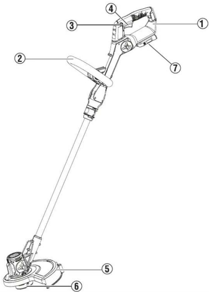
UNDERSTANDING THE STRING TRIMMER
See Figure 1 and the Component Table.
To reduce the risk of personal injury and product failure, read and understand the information in this user manual and the information on the product labeling.
| COMPONENT TABLE | ||
| INDEX NUMBER C | COMPONENT DESCRIPTION | |
| 1 Top handle Prov | des directional control and stability during use. | |
| 2 Auxiliary handle | Provides additional comfort and stability during use. | |
| 3 Lock-out button | Prevents the string trimmer from initiating operation accidentally. | |
| 4 Switch trigger In | Initiates operation when squeezed in conjunction with holding the lock-out button. The switch trigger must be held throughout use or the string trimmer will not operate. | |
| 5 Guard Provides | protection from debris and contact with the trimming wire. | |
| 6 Spool housing St | storage for the wire used during operation. | |
| 7 Battery pack hou | sing Location of the battery pack for connection and disconnection to the unit. | |
REMOVING CARTON CONTENTS

WARNING
This product requires assembly. Do not attempt to operate this product if any items in the INCLUDED LIST
are already assembled when you remove the carton contents. These items are not assembled by the manufacturer and should require customer assembly. Using an improperly assembled product can be hazardous and could result in serious personal injury.
- Carefully open the carton.
- Remove and inspect the carton contents. Verify that all the items in the INCLUDED LIST are present and undamaged.
- Recycle or dispose of the packaging materials properly.
| INCLUDED LIST | |
| ITEM QUANTITY | |
| Auxiliary handle 1 | |
| Guard 1 | |
| Top handle 1 | |
| Spool housing 1 | |
If any parts are missing, contact our service team at service@wpowereq.com or call 1-855-944-3571.

WARNING
Do not alter or modify this product unless instructed otherwise in this manual or by the manufacturer. Do accessories that are not recommended for use with this product. Making unauthorized modifications and essories can damage the unit and may void your warranty.

WARNING
Do not connect the string trimmer to the battery pack until assembly is complete. Failure to comply could ting and possible serious personal injury.
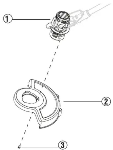
ATTACHING THE GUARD TO THE SPOOL HOUSING
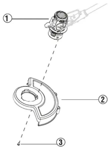
- See Figure 2. Remove the screw (1) from the spool housing. Keep the screw for use later.
- See Figure 3. Attach the guard to the spool housing.
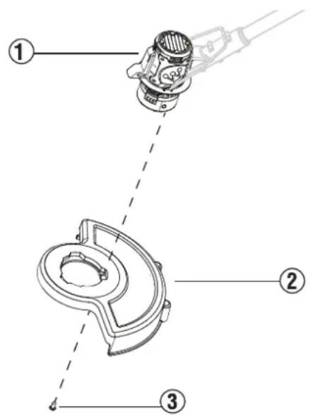
- Align the markers on the guard (2) with the markers on the spool housing (1). Rotate the guard until the markers on the guard are secured into place.
- See Figure 4. With the guard (2) attached to the spool housing (1), secure the guard to the spool housing with the screw (3).
Figure 2
(a) underneath view of the spool housing
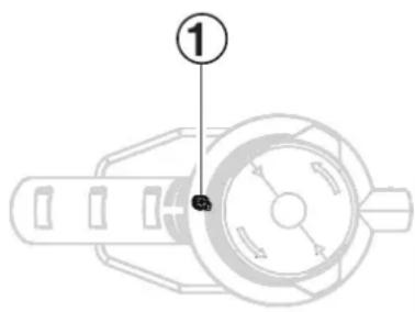
Figure 3
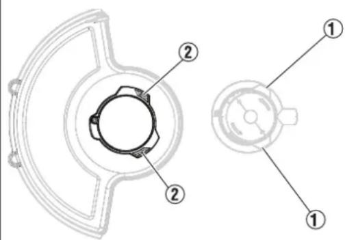
Figure 4
ATTACHING THE AUXILIARY HANDLE TO THE STRING TRIMMER ASSEMBLY
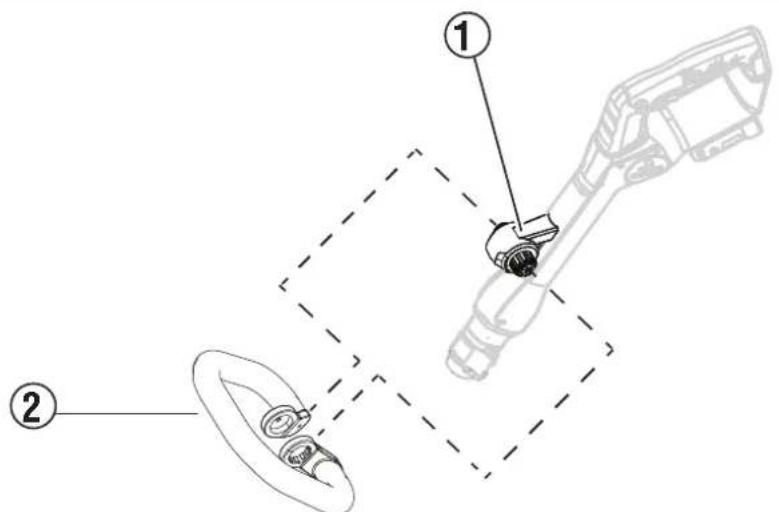
- See Figure 5. Press the auxiliary handle (2) on the attachment body (1) on the string trimmer. The auxiliary handle will click and lock in place.
Figure 5
USING THE TELESCOPIC FUNCTION
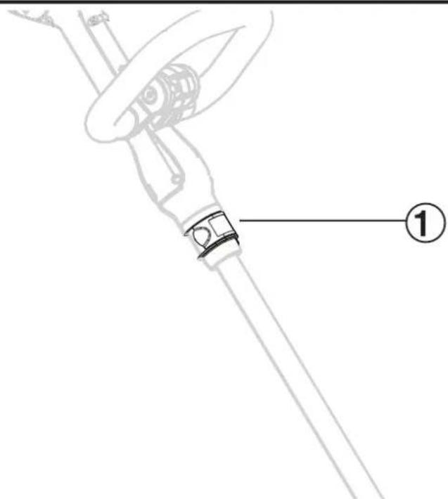
- See Figure 6. Raise the latch (1) from the body of the string trimmer.
- Extend the tube as needed to the desired length.
- Close the latch to lock the tube in place.
Figure 6
WARNING Always disconnect the battery pack from the string trimmer when assembling parts, making adjustments, cleaning, or when not in use.
ATTACHING THE BATTERY PACK
- Insert the battery pack into the battery housing.
- Be sure that the latches on each side of the battery pack lock into place.
WARNING
Remove the battery pack and keep hands clear of the lockout button when carrying or transporting the

WARNING
Always wear eye protection with side shields marked to comply with ANSI Z87.1. Failure to do so could thrown into your eyes resulting in possible serious injury.

WARNING
Do not use any attachments or accessories not recommended by the manufacturer of this product. The accessories not recommended can result in serious personal injury.
NOTICE
Before each use, inspect the entire product for damaged, missing, or loose parts such as screws, nuts, bolts,
and caps. Tighten securely all fasteners and caps and do not operate this product until all missing or damaged parts are replaced. Please contact customer service.

WARNING
To avoid serious personal injury, always remove the battery pack and keep hands clear of the lock-out
button when carrying or transporting the tool.
STARTING THE STRING TRIMMER
- Install the battery pack.
- Press and hold the lockout button. While holding the lockout button, squeeze the switch trigger.
- To stop the string trimmer, release the switch trigger.
OPERATING TIPS
- Keep a firm grip with both hands while in operation.
- The string trimmer should be held at a comfortable position with the top handle about hip height.
- Cut tall grass from the top down. This will prevent grass from wrapping around the boom housing and string head which may cause damage from overheating.
- If grass becomes wrapped around the string head:
- Remove the battery pack.
- Remove the grass.
- Keep the trimmer tilted toward the area being cut; this is the best cutting area.
- The string trimmer cuts when passing the unit from side to side. This will avoid throwing debris at the operator. Avoid cutting in the dangerous area shown.
- Use the tip of the line to do the cutting; do not force string head into uncut grass.
• Wire and picket fences cause extra line wear, even breakage. Stone and brick walls, curbs, and wood may wear line rapidly. - Avoid trees and shrubs. Tree bark, wood moldings, siding, and fence posts can easily be damaged by the line.

WARNING
Always hold the string trimmer away from the body. Keep clearance between the body and the string trim-
mer. Any contact with the string trimmer cutting head while operating can result in serious personal injury.
ADVANCING THE TRIMMER LINE
NOTICE
The trimmer is equipped with an auto-feed head. Bumping the head to try to advance the line will damage the
trimmer and void the warranty.
- With the trimmer running, release the switch trigger.
- Wait two seconds, and press the switch trigger.
NOTICE
The line will extend approximately 1/4 in. with each stop and start of the switch trigger until the line reaches the
length of the grass deflector cut-off blade.
- Resume trimming.
ADVANCING THE LINE MANUALLY
- Remove the battery pack.
- Push the button located on the string head while pulling on line to manually advance the line.
EDGE TRIMMING
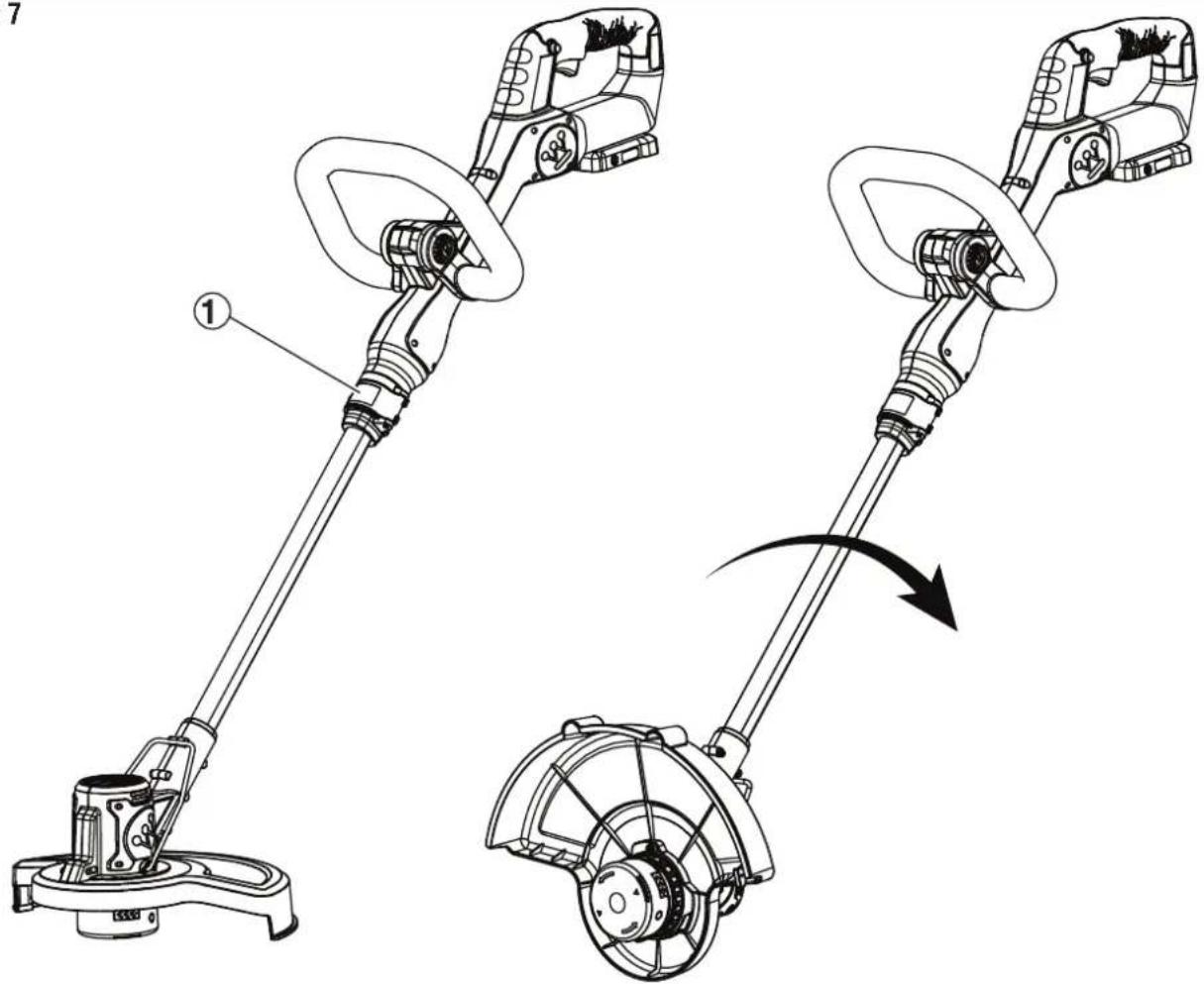
- See Figure 7. Raise the latch (1) from the string trimmer body.
- Rotate the aluminum tube by 180°.
- Close the latch to lock the tube in position.
Figure 7
WARNING Before inspecting, cleaning or servicing the unit, stop the motor, wait for all moving parts to stop, and disconnect the battery pack from the string trimmer. Failure to follow these instructions can result in serious personal injury or property damage.
WARNING Always wear eye protection with side shields marked to comply with ANSI Z87.1. Failure to do so could result in objects being thrown into your eyes resulting in possible serious injury.
NOTICE Periodically inspect the entire product for damaged, missing, or loose parts such as screws, nuts, and caps. Secure all fasteners and caps. Do not operate this product if parts are missing or damaged. Please contact customer service.
GENERAL MAINTENANCE
Avoid using solvents when cleaning plastic parts. Most plastics are susceptible to damage from various types of commercial solvents and may be damaged by their use. Use clean cloths to remove dirt, dust, oil, and grease.
WARNING Do not let brake fluids, gasoline, petroleum-based products, or penetrating oils come in contact with plastic parts. Chemicals can damage, weaken, or destroy plastic which can result in serious personal injury.
SPOOL REPLACEMENT
Use only 0.065 in. diameter round or twisted or 0.080 in. diameter twisted line. Use original manufacturer's replacement line for best performance.
- Remove the battery pack.
- Push in tabs on side of spool retainer.
- Pull spool retainer up to remove.
- Remove the old spool.
- To install the new spool, be sure the line is captured in the slot on the new spool. Be sure the end of the line is extended approximately 6 in. beyond the slot.
- Install the new spool so that the line and slot align with the eyelet in the string head. Thread the line into the eyelet.
- Pull the line extending from the string head so the line releases from the slot in the spool.
- Reinstall the spool retainer by depressing tabs into slots and pushing down until spool retainer clicks into place.
LINE REPLACEMENT
- Remove the battery pack.
- Remove the spool retainer.
- Remove the spool from the string head.
NOTE: Remove any old line remaining on the spool. - Cut a piece of line approximately 9 ft. long.
- Use only 0.065 in. diameter round or twisted or 0.080 in. diameter twisted line.
- Insert the line into the anchor hole in the upper part of the spool. Wind the line around the upper part of the spool clockwise, as shown by the arrows on the spool. Place line in the slot on upper spool flange, leaving about 6 in. extended beyond the slot. Do not overfill. After winding the line, there should be at least 1/4 in. between the wound line and the outside edge of the spool.
- Replace the spool retainer, spool, and the spool retainer.
STORING THE STRING TRIMMER
- Remove the battery pack.
- Clean all foreign material from the trimmer.
- Store it in a place that is inaccessible to children.
- Keep away from corrosive agents.
| PROBLEM POSSIBLE | CAUSE CORRECTION | |
| Trimmer runs slowly | Check that the spool housing can rotate freely Carefully clean it if necessary | |
| Check that the cutting line does not protrude more than approximately 5-3/8 inches (136mm) from the spool. | If it does, cut it off so that it just reaches the line trimming blade. | |
| Trimmer will not start | Battery pack not installed properly Check battery pack installation | |
| Battery pack not charged Check battery pack charging requirements | ||
| Battery pack will not charge | Surrounding air temperature too hot or too cold | Move charger and tool to a surrounding air temperature of above 40 degree F (4.5°C) or below 105 degree F (+40.5°C). |
| Charger not plugged in | Plug charger into a working outlet.Check current at receptacle by plugging in a lamp or other appliance.Check to see if receptacle is connected to a light switch which turns power off when you turn out the lights. | |
| Battery pack not inserted into charger Insert battery | pack into charger until red LED appears | |
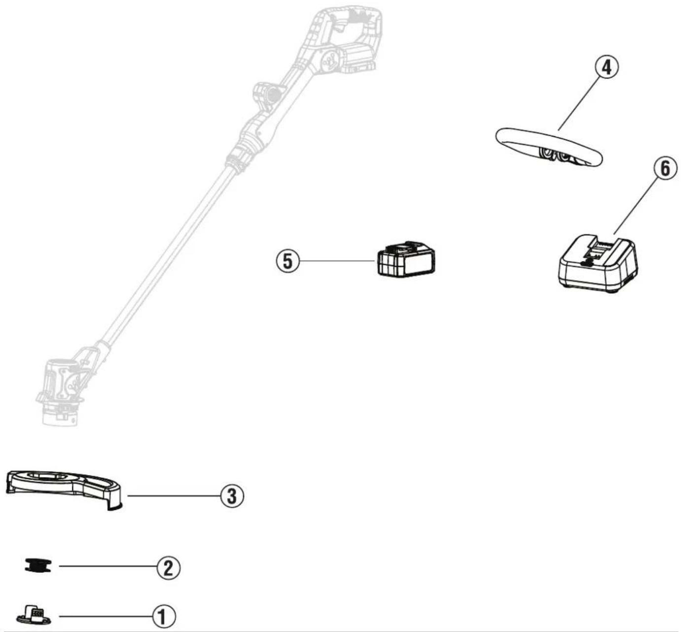
| Index Number Description Part Number | ||
| 1 Spool retainer | WST 20VSC | |
| 2 Spool (1-pack) | WST 20VSpool1 | |
| 3 Guard 120160001 | ||
| 4 Auxiliary handle | 120170002 | |
| 5 Battery pack W20V2AH | ||
| 6 Charger W20V2AMP | ||
| * Spool (3-pack) | WST 20VSpool3 | |
PRESUPUESTO
Figura 3
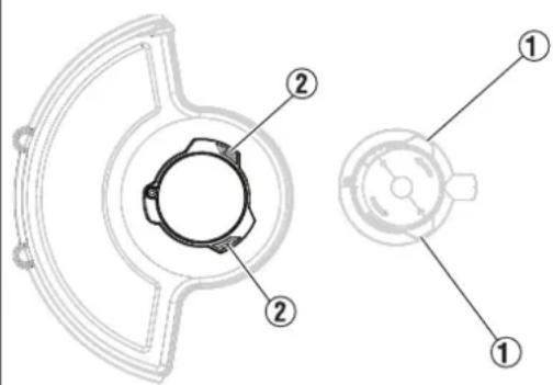
Figura 4
CÓMO CONECTAR EL MANGO AUXILIAR AL CONJUNTO DE LA RECORTADORA DE HILO
REEMPLAZO DE CARRETE
CARACTÉRISTIQUES
Tension continue 20 V
AVEZ-VOUS DES QUESTIONS?
COMPRENDRE LE COUPE-BORDURES
Figure 3
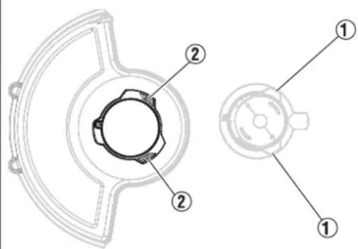
Figure 4
FIXATION DE LA POIGNÉE AUXILIAIRE À L'ENSEMBLE COUPE-BORDURES
UTILISATION DE LA FONCTION TÉLESCOPIQUE
natural_image
Blue square icon with a white crown and rounded rectangle (no text or symbols)www.westinghouse.com
Service Hotline (855) 944-3571
777 Manor Park Drive, Columbus, OH 43228
and Westinghouse are trademarks of Westinghouse Electric Corporation.
Used under license by Westinghouse Outdoor Power Equipment.
© 2025 Westinghouse Outdoor Power Equipment, All Rights Reserved.

- User Manual
- INTRODUCTION
- WARNING
- DISCLAIMERS
- ALL RIGHTS RESERVED
- DANGER
- UPDATES
- PRODUCT REGISTRATION
- For Your Records
- SPECIFICATIONS
- SAFETY DEFINITIONS
- SAFETY SYMBOLS
- General power tool safety warnings
- READ AND UNDERSTAND ALL IN-
- Save all warnings and instructions for future reference.
- Work area safety
- Electrical safety
- Personal safety
- Power tool use and care
- Battery tool use and care
- Service
- Lawn trimmer and lawn edge trimmer safety warnings
- UNDERSTANDING THE STRING TRIMMER
- REMOVING CARTON CONTENTS
- ATTACHING THE GUARD TO THE SPOOL HOUSING
- ATTACHING THE AUXILIARY HANDLE TO THE STRING TRIMMER ASSEMBLY
- USING THE TELESCOPIC FUNCTION
- ATTACHING THE BATTERY PACK
- NOTICE
- STARTING THE STRING TRIMMER
- OPERATING TIPS
- ADVANCING THE TRIMMER LINE
- ADVANCING THE LINE MANUALLY
- EDGE TRIMMING
- GENERAL MAINTENANCE
- SPOOL REPLACEMENT
- LINE REPLACEMENT
- STORING THE STRING TRIMMER
- PRESUPUESTO
- CÓMO CONECTAR EL MANGO AUXILIAR AL CONJUNTO DE LA RECORTADORA DE HILO
- REEMPLAZO DE CARRETE
- CARACTÉRISTIQUES
- AVEZ-VOUS DES QUESTIONS?
- COMPRENDRE LE COUPE-BORDURES
- FIXATION DE LA POIGNÉE AUXILIAIRE À L'ENSEMBLE COUPE-BORDURES
- UTILISATION DE LA FONCTION TÉLESCOPIQUE
Brand : WESTINGHOUSE
Model : WSTT20V
Category : Electric lawn mower