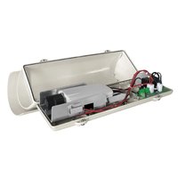
VERSO POLAR - Camera case Videotec - Free user manual and instructions
Find the device manual for free VERSO POLAR Videotec in PDF.


| Product type | Outdoor camera housing with integrated heater |
| Brand | Videotec |
| Model | VERSO POLAR |
| Material | High-strength polycarbonate, double ABS roof |
| Color | RAL9002 |
| Usable interior dimensions (LxH) | 270 x 70 x 70 mm |
| Optical window | 105 x 64 mm in polycarbonate |
| Net weight | 1.5 kg |
| Power supply (heater version) | 12-24 Vdc 5 A max / 12-24 Vac 5 A max / 120-230 Vac 700 mA max |
| Camera power supply | 100-240 Vac → 12 Vdc 1.25 A or 230 Vac → 24 Vac 400 mA |
| Temperature range | -55°C to +60°C (with heater) |
| IP protection rating | IP66 (with cable glands or internal support with seals) |
| IK impact resistance | IK10 |
| Certifications | CE (EN60950-1, EN62368-1), cULus Type 4X, EAC, FCC Class B |
| Cable glands | 3xM16 nickel-plated brass |
| Opening | Side with hinges, secured by 2 screws |
| Main features | Efficient heating, 70x70 mm interior space, stainless steel screws, internal slide |
| Maintenance and cleaning | Soft cloth and diluted neutral soap; avoid solvents, alcohol, strong acids |
| Safety | Installation by qualified personnel; disconnect power before intervention; use bipolar switch |
| Spare parts and repairability | Use only original parts (heater kits, power supply, fan, etc.) |
| Warranty | Warranty void if unauthorized modification is made |
| General information | Anti-vandal housing, suitable for most cameras and lenses on the market |
Frequently Asked Questions - VERSO POLAR Videotec
User questions about VERSO POLAR Videotec
0 question about this device. Answer the ones you know or ask your own.
Ask a new question about this device
Download the instructions for your Camera case in PDF format for free! Find your manual VERSO POLAR - Videotec and take your electronic device back in hand. On this page are published all the documents necessary for the use of your device. VERSO POLAR by Videotec.
USER MANUAL VERSO POLAR Videotec
VERSO, VERSO COMPACT, VERSO POLAR
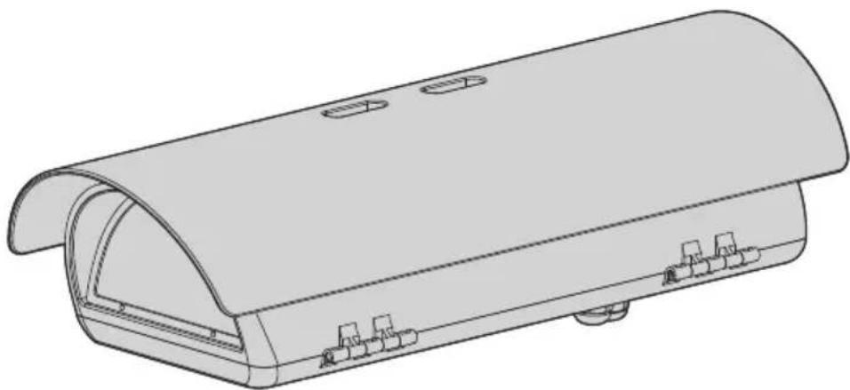
Side-opening polycarbonate camera housing
natural_image
Technical line drawing of a mechanical component with arched top and internal slots (no text or symbols)EN English - Instruction manual
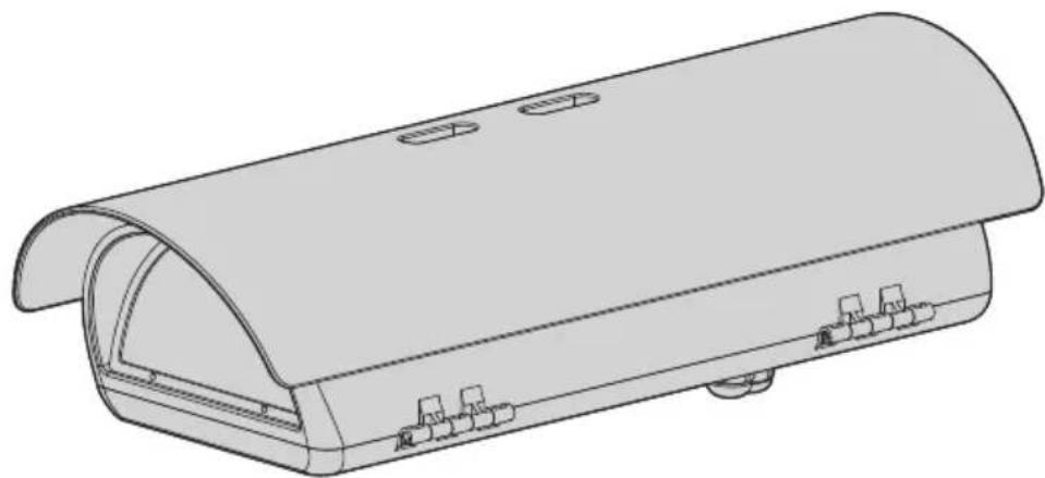
Side-opening polycarbonate camera housing
natural_image
Technical line drawing of a mechanical enclosure or housing component (no text or symbols)Contents
1 About this manual....5
1.1 Typographical conventions .... 5
2 Notes on copyright and information on trademarks....5
3 Safety rules ....5
4 Identification ....7
4.1 Product description and type designation....7
4.1.1 VERSO 7
4.1.2 VERSO COMPACT 7
4.1.3 VERSO POLAR....7
4.2 Product marking label....7
5 Preparing the product for use....8
5.1 Unpacking....8
5.2 Contents 8
5.3 Safely disposing of packaging material....8
5.4 Preparatory work before installation....8
5.4.1 Mounting the bracket....8
6 Installation....9
6.1 Housing opening....9
6.2 How to install the camera....9
6.3 Board description....10
6.4 Connecting the power supply 12
6.4.1 Type of cable 12
6.5 Installation of the version with double filter for air renewal 12
6.6 Desiccant bag....12
7 Accessories....13
7.1 Heater....13
7.1.1 Heater installation....13
7.2 Camera power supply....13
7.2.1 Camera power supply installation 13
7.3 Blower 14
7.3.1 Blower installation....14
8 Cleaning 14
8.1 Cleaning the window and plastic parts 14
9 Information on disposal and recycling 14
10 Technical data.... 15
10.1 VERSO 15
10.1.1 General 15
10.1.2 Mechanical....15
10.1.3 Electrical 15
10.1.4 Environment....15
10.1.5 Certifications....15
10.2 VERSO COMPACT 16
10.2.1 General....16
10.2.2 Mechanical 16
10.2.3 Electrical....16
10.2.4 Environment....16
10.2.5 Certifications 16
10.3 VERSO POLAR.... 17
10.3.1 General....17
10.3.2 Mechanical 17
10.3.3 Electrical....17
10.3.4 Environment 17
10.3.5 Certifications 17
11 Technical drawings....18
1 About this manual
Read all the documentation supplied carefully before installing and using this product. Keep the manual in a convenient place for future reference.
1.1 Typographical conventions

DANGER!
High level hazard.
Risk of electric shock. Disconnect the power supply before proceeding with any operation, unless indicated otherwise.

CAUTION!
Medium level hazard.
This operation is very important for the system to function properly. Please read the procedure described very carefully and carry it out as instructed.

INFO
Description of system specifications.
We recommend reading this part carefully in order to understand the subsequent stages.
2 Notes on copyright and information on trademarks
The mentioned names of products or companies are trademarks or registered trademarks.
3 Safety rules

CAUTION! Device installation and maintaining must be performed by specialist technical staff only.
- CAUTION! The electrical system to which the unit is connected must be equipped with an automatic bipolar circuit breaker. The circuit breaker for main supply voltage phase units must have a level of intervention of 20A max. The circuit breaker for low voltage units must have a level of intervention of 6A max. This circuit breaker must be of the Listed type. The minimum distance between the circuit breaker contacts must be 3mm (0.1in). The circuit breaker must be provided with protection against the fault current towards the ground (differential) and the overcurrent (magnetothermal).
- The manufacturer declines all responsibility for any damage caused by an improper use of the appliances mentioned in this manual. Furthermore, the manufacturer reserves the right to modify its contents without any prior notice. The documentation contained in this manual has been collected and verified with great care. The manufacturer, however, cannot take any liability for its use. The same thing can be said for any person or company involved in the creation and production of this manual.
- Before starting any operation, make sure the power supply is disconnected.
- Be careful not to use cables that seem worn or old.
- Never, under any circumstances, make any changes or connections that are not shown in this handbook. Improper use of the appliance can cause serious hazards, risking the safety of personnel and of the installation.
-
Use only original spare parts. Non-original spare parts could cause fire, electrical discharge or other hazards.
-
Comply with all the national standards during the device installation.
- This device was designed to be permanently secured and connected on a building or on a suitable structure. The device must be permanently secured and connected before any operation.
- Before proceeding with installation, check the supplied material to make sure it corresponds to the order specification by examining the identification labels (4.2 Product marking label, page 7).
- Any device which could be installed inside the product must comply with the current safety rules.
- If the installation is NEMA TYPE 4X, the installer must replace the cable glands of the product with NEMA TYPE 4X cable glands.
- For all connections, use cables that are able to withstand temperatures of at least 75^ (167°F).
- The product is designed to house only cameras that are properly certified according to IEC/UL 60950-1 or IEC/UL 62368-1 (7W max).
- A power disconnect device must be included in the electrical installation, and it must be very quickly recognizable and operated if needed.
-
To connect the power supply line use the appropriate junction-box (UPTJBUL). For further information, refer to the product use and installation manual.
-
Use Listed tube crimping lugs for the connection of the network conductors to the terminals. The copper tube crimping lugs must be suitable for the type of installation (from -20^ (-4^) a +80^ (+176^) min., V-0). Copper tube crimping lugs examples: RP, BP o YP (Cembre).
- Installation category (also called Overvoltage Category) specifies the level of mains voltage surges that the equipment will be subjected to. The category depends upon the location of the equipment, and on any surge voltage protection provided. Equipment in an industrial environment, directly connected to major feeders/short branch circuits, is subjected to Installation Category III. If this is the case, a reduction to Installation Category II is required. This can be achieved by use of an insulating transformer with an earthed screen between primary and secondary windings, or by fitting UL listed Surge Protective Devices (SPDs) from live to neutral and from neutral to earth. Listed SPDs shall be designed for repeated limiting of transient voltage surges and the following rated operation conditions: Type 2 (SPDs permanently connected to the power network and intended for installation on the load side of the service equipment); Nominal Discharge Current (In) 20kA min. For example: FERRAZ SHAWMUT, STT2240SPG-CN, STT2BL240SPG-CN rated 120Vac/240Vac, (In=20kA). Maximum distance between installation and reduction is 5m.
4 Identification
4.1 Product description and type designation
4.1.1 VERSO
Sturdy, tamper-proof housing designed to simplify installation and service and guarantee total protection against all environmental conditions.
Its dimensions make it suitable for a variety of combinations of cameras and lenses.
Entirely constructed from technopolymer, it guarantees high impact resistance and perfect weather protection from external agents and UV rays.
Very easy to install thanks to the side-opening system that allows the full access to the camera, lenses and all internal connections.
The housing proposes various mounting options, wall or ceiling brackets, feedthrough and non-feedthrough, or Pan & Tilt head.
4.1.2 VERSO COMPACT
Entirely constructed from technopolymer, it guarantees high impact resistance and perfect weather protection from external agents and UV rays.
4.1.3 VERSO POLAR
This housing is provided with a high performance heating system which it will continue working at even the most severe temperatures, right down to-55°C (-67°F).
4.2 Product marking label
See the label attached to the product.
5 Preparing the product for use

Any change that is not expressly approved by the manufacturer will invalidate the warranty.
5.1 Unpacking
When the product is delivered, make sure that the package is intact and that there are no signs that it has been dropped or scratched.
If there are obvious signs of damage, contact the supplier immediately.
When returning a faulty product we recommend using the original packaging for shipping.
Keep the packaging in case you need to send the product for repairs.
5.2 Contents
Check the contents to make sure they correspond with the list of materials as below:
- Housing
• Housing equipment: - Allen wrench
- Spacers
- Cable glands gaskets
- Cable glands (x3)
- Bolts and screws
- Screws for camera
- Instruction manual
5.3 Safely disposing of packaging material
The packaging material can all be recycled. The installer technician will be responsible for separating the material for disposal, and in any case for compliance with the legislation in force where the device is to be used.
5.4 Preparatory work before installation
5.4.1 Mounting the bracket

The product must be fastened with suitable equipment. The fastening means must guarantee mechanical sealing when a force equal to at least 4 times the weight of the device is applied.
6 Installation
6.1 Housing opening
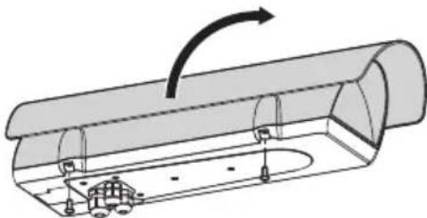
Loosen the 2 screws on the side, turn the cover and the upper half of the body about the opening hinge axis.
natural_image
Diagram of a mechanical component with a curved arrow indicating rotation or force direction (no text or symbols present)Fig. 1

After installation and wiring, close the product.
6.2 How to install the camera
Open the housing as described in the relative chapter (6.1 Housing opening, page 9).
Partially loosening the fastening screws (01).
Remove the internal slide (02) by sliding it until the holes coincide with the slide fastening screws.
Fasten the camera with the 1/4" screw (03). To position the camera and lens correctly, if necessary, use the supplied spacers. (04).
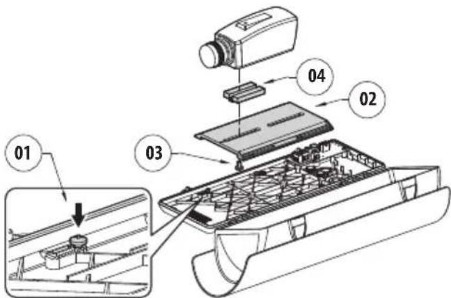
Fig. 2
Reposition the internal slide and tighten the screws that had been loosened previously.
Remove the conductors protective sheathing and connect them to terminal (camera power supply, 6.3 Board description, page 10).
The camera's power supply cable conductors must be tied up with a cable tie next to the terminal. Keep the signalling and power supply cables separated from each other.
6.3 Board description

Connect the safety earth to the relative terminal of the power supply connector.

The board may appear different to that illustrated.

Depending on the product version, the board may not be equipped with all functions.
| BOARD DESCRIPTION (VERSO, VERSO COMPACT) | ||
| Connector | Function Notes | |
| J1 Camera power supply ( V_OUT ) | Depending on the power supply model the two connectors have different use.If powered in 12vdc connector A corresponds to polarity +, while connector B corresponds to polarity -.If powered in 24vac connectors A and B are equivalent and correspond to the voltage Vac. | |
| J2 Heater power supply | ||
| J3 Power supply for the board ( V_IN ) | ||
| J4 Auxiliary output ( V_OUT ) | Same voltage applied on J3 | |
| J5 Power supply connector/jumper | Jumper present only in ventilated models | |
| J6 Fan power supply | ||
| SW1 Tamper switch Only some models | ||
Tab. 1
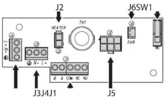
Fig. 3 VERSO.
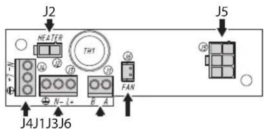
Fig. 4 VERSO COMPACT.
| BOARD DESCRIPTION (VERSO, VERSION WITH DOUBLE FILTER FOR AIR RENEWAL) | ||
| Connector | Function Notes | |
| J1 Power supply for the board ( V_IN ) | ||
| J2 Auxiliary output ( V_OUT ) | Same voltage applied on J1 | |
| J3 Heater power supply | ||
| J4 Tamper switch contacts | Only some models | |
| J5 Camera power supply ( V_OUT ) | Depending on the power supply model the two connectors have different use.If powered in 12vdc connector A corresponds to polarity +, while connector B corresponds to polarity -.If powered in 24vac connectors A and B are equivalent and correspond to the voltage Vac. | |
| J7 Power supply connector/jumper | Jumper present only in ventilated models | |
| J8 Fan power supply | ||
| SW1 Tamper switch Only some models | ||
Tab. 2
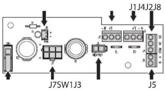
Fig. 5 VERSO (version with double filter for air renewal).
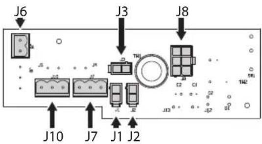
| BOARD DESCRIPTION (VERSO POLAR) | ||
| Connector | Function | Notes |
| J1, J2, J3 | Heater power supply | |
| J6 | Camera power supply ( V_OUT ) | |
| J7 | Power supply for the board ( V_IN ) | Depending on the power supply model the two connectors have different use.If powered in 12vdc connector A corresponds to polarity +, while connector B corresponds to polarity -.If powered in 24vac connectors A and B are equivalent and correspond to the voltage Vac. |
| J8 | Power supply connector /jumper | Only available in 12V Dc / 24 Vac versions |
| J10 | Auxiliary output ( V_OUT ) | Same voltage applied on J7 |
Tab. 1
6.4 Connecting the power supply

Earth cable should be about 10mm longer than the other two, so that it will not be disconnected accidentally if pulled.
Insert the cables inside the housing using the cable glands. The cable glands are suitable for conductors with diameters of between 5mm and 10mm. The section of the cable inside the housing must be sufficiently long to allow connection. Suitably lock the cable glands.
Remove the conductors protective sheathing and connect them to terminal (Power supply for the board, 6.3 Board description, page 10).
6.4.1 Type of cable
The cable used for the connection to the power supply line must be suitable for the intended use. Comply with the current national standards on electrical installations.
6.5 Installation of the version with double filter for air renewal

During installation pay attention to the orientation of the air inlet filter fins.
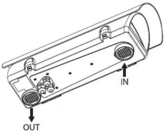
Fig. 7
Depending on the angle of inclination of the housing, the orientation of the filter fins must prevent water penetrating in case of rain:
To guarantee weatherproof protection, install the housing on the support following the inclination limits as shown in the picture.
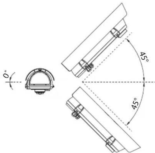
Fig. 8 Maximum tilt of the transversal axis: 0°. Maximum tilt of the longitudinal axis: ±45°.
6.6 Desiccant bag
Take the dessicant salt bag out of its pack and insert it into the product.
7 Accessories

For further details on configuration and use, refer to the relative manual.
7.1 Heater
7.1.1 Heater installation
Open the housing as described in the relative chapter (6.1 Housing opening, page 9).
Fix the heater kit to the prearranged points on the body of the housing.
The pre-wired heating element (01) should be positioned between the 2 dissipators (02) before attachment to ensure contact and hence guarantee correct heat transmission.
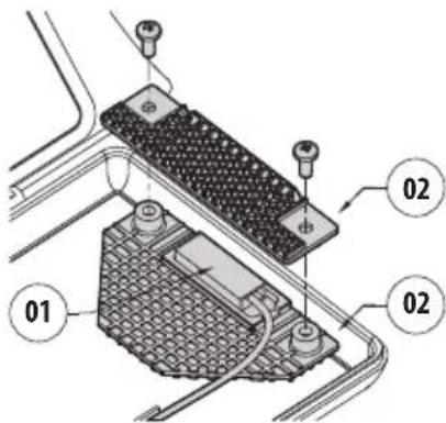
Fig. 9
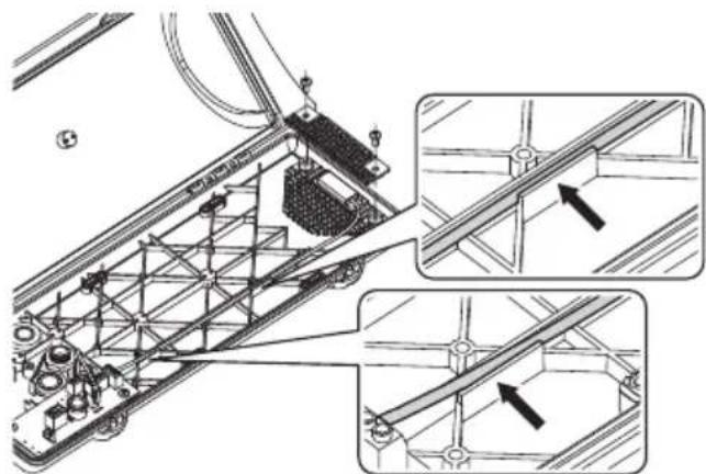
Pass the heating wiring into the provided seatings.
natural_image
Technical line drawing of a mechanical assembly with structural supports and mounting brackets (no text or symbols)Fig. 10 Reposition the internal slide and tighten the screws that had been loosened previously.
7.2 Camera power supply
7.2.1 Camera power supply installation

Pay attention to the voltage used to power the circuit. Depending on requirements use the correct power supply kit.
Usable power supplies:
• IN from 100Vac up to 240Vac, 50/60Hz - OUT 12Vdc, 1.25A
• IN 230Vac, 50Hz - OUT 24Vac, 50Hz, 400mA
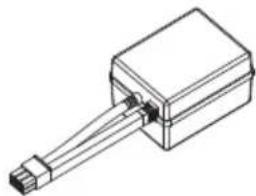
natural_image
Technical line drawing of a rectangular electronic component with a protruding shaft (no text or symbols)Fig. 11 Camera power supply.
Open the housing as described in the relative chapter (6.1 Housing opening, page 9).
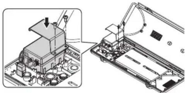
Position the camera power supply in the provided seating, parallel to the support ribs. Fix the power supply to the body of the housing using the corner bracket and screws supplied in the camera power supply kit.
natural_image
Technical illustration of a mechanical assembly with a disassembled base and a crane lifting a component (no text or symbols present)Fig. 12
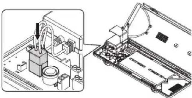
At the end of installation, connect the wiring to the terminal (power supply connector, 6.3 Board description, page 10).
natural_image
Technical illustration of an electronic device with a 3D printer assembly (no text or symbols visible)Fig. 13
7.3 Blower
7.3.1 Blower installation

Not usable in versions with double filter for air renewal.

Pay attention to the voltage used to power the circuit. Depending on requirements use the correct power supply kit.

The blower kit should be assembled according to the instructions to ensure a correct air circulation inside the housing.
Open the housing as described in the relative chapter (6.1 Housing opening, page 9).
Fix the blower using the corner bracket and screws.
The VERSO housing is provided with a single installation location for the blower (01). In VERSO COMPACT housing you can choose between two different installation locations (02).
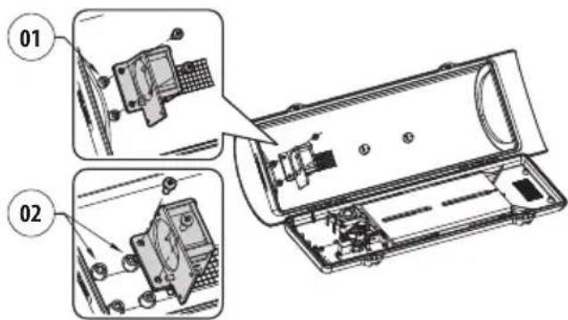
Fig. 14
8 Cleaning
8.1 Cleaning the window and plastic parts

Avoid ethyl alcohol, solvents, hydrogenated hydrocarbide, strong acid and alkali. Such products may irreparably damage the surface.
We recommend using a soft cloth with neutral soap diluted with water or specific products to clean the lenses.
9 Information on disposal and recycling
The European Directive 2012/19/EU on Waste Electrical and Electronic Equipment (WEEE) mandates that these devices should not be disposed of in the normal flow of municipal solid waste, but they should be collected separately in order to optimize the recovery stream and recycling of the materials that they contain and to reduce the impact on human health and the environment due to the presence of potentially hazardous substances.
The symbol of the crossed out bin is marked on all products to remember this.
The waste may be delivered to appropriate collection centers, or may be delivered free of charge to the distributor where you purchased the equipment at the time of purchase of a new equivalent or without obligation to a new purchase for equipment with size smaller than 25cm (9.8in).
For more information on proper disposal of these devices, you can contact the responsible public service.
10 Technical data
10.1 VERSO
10.1.1 General
Made of strong technopolymer (polycarbonate)
Sunshield in ABS
RAL9002 Colour
Stainless steel external screws
10.1.2 Mechanical
Internal usable dimensions (WxH): 70x70mm (2.7x2.7in)
Internal usable length (with or without accessories): 270mm (10.6in)
Cable glands: 3xM16
Polycarbonate window (WxH): 105x64mm (4.1x2.5in)
Unit weight: 1.5kg (3.3lb)
10.1.3 Electrical
Supply voltage/Current consumption (empty version):
• From 12Vdc up to 24Vdc, 1A max
• From 12Vac up to 24Vac, 1A max, 50/60Hz
• From 120Vac up to 230Vac, 400mA max, 50/60Hz
Supply voltage/Current consumption (version with heater, Ton 15°C±3°C (59°F ±5°F), Toff 22°C±3°C (72°F±5°F)):
• From 12Vdc up to 24Vdc, 5A max
• From 12Vac up to 24Vac, 5A max, 50/60Hz
• From 120Vac up to 230Vac, 700mA max, 50/60Hz
Supply voltage/Current consumption (version with heater fan assistant, continuous duty):
- 12Vdc, 400mA max
• 24Vac, 200mA max, 50/60Hz - From 100Vac up to 240Vac, 40mA max, 50/60Hz (with wide-range power supply)
Supply voltage/Current consumption (version with blower and thermostat for models with double filter for air renewal, Ton 35^ C±3°C ( 95^ F±5°F), Toff 20^ C±3°C ( 71^ F±5°F)):
- 12Vdc, 400mA max
• 24Vac, 200mA max, 50/60Hz
Camera power supply:
- IN from 100Vac up to 240Vac, 50/60Hz - OUT 12Vdc, 1.25A
• IN 230Vac, 50Hz - OUT 24Vac, 50Hz, 400mA
10.1.4 Environment
For indoors and outdoors installation
Operating temperature (with heater): From -20^ (-4°F) up to +60^ (140°F)
Chemical agents resistance
• High resistance: basics, alcohols, gas, hydrocarbon
• Good resistance: Organic acids, inorganic acids, oils
- Low resistance: Solvents
10.1.5 Certifications
Electrical safety (CE): EN60950-1, IEC60950-1, EN62368-1, IEC62368-1
Electromagnetic compatibility (CE): EN50130-4, EN61000-6-3, EN55032 Class B, FCC Part. 15 Class B, ICES-003 Class B
Outdoor installation (CE): EN60950-22, IEC 60950-22
IP protection degree (EN60529):
- IP66/IP67 (with cable glands)
- IP66/IP67 (with bracket with internal cable channel, with sealing rings)
• IP55 (with bracket with internal cable channel) - IP44 (for models with a double filter for air renewal)
IK protection degree (EN62262): IK10
UL certification:
- cULus Listed, TYPE 4X (except for versions with double filter for the air exchange)
• UL94, V1 (fire-self extinguish)
EAC certification
10.2 VERSO COMPACT
10.2.1 General
Made of strong technopolymer (polycarbonate)
Sunshield in ABS
RAL9002 Colour
Stainless steel external screws
10.2.2 Mechanical
Internal usable dimensions (WxH): 63x63mm (2.5x2.5in)
Internal usable length (with or without accessories): 210mm (8.3in)
Cable glands: 2xM16
Polycarbonate window (WxH): 98x55mm (3.9x2.2in)
Unit weight: 1.1kg (2.2lb)
10.2.3 Electrical
Supply voltage/Current consumption (empty version):
• From 12Vdc up to 24Vdc, 1A max
• From 12Vac up to 24Vac, 1A max, 50/60Hz
• From 120Vac up to 230Vac, 400mA max, 50/60Hz
Supply voltage/Current consumption (version with heater, Ton 15°C±3°C (59°F ±5°F), Toff 22°C±3°C (72°F±5°F)):
• From 12Vdc up to 24Vdc, 5A max
• From 12Vac up to 24Vac, 5A max, 50/60Hz
• From 120Vac up to 230Vac, 700mA max, 50/60Hz
Supply voltage/Current consumption (version with heater fan assistant, continuous duty):
- 12Vdc, 400mA max
• 24Vac, 200mA max, 50/60Hz - From 100Vac up to 240Vac, 40mA max, 50/60Hz (with wide-range power supply)
Camera power supply:
- IN from 100Vac up to 240Vac, 50/60Hz - OUT 12Vdc, 1.25A
• IN 230Vac, 50Hz - OUT 24Vac, 50Hz, 400mA
10.2.4 Environment
For indoors and outdoors installation
Operating temperature (with heater): from -20^ (-4°F) up to +60^ (140°F)
Chemical agents resistance
• High resistance: basics, alcohols, gas, hydrocarbon
• Good resistance: Organic acids, inorganic acids, oils
- Low resistance: Solvents
10.2.5 Certifications
Electrical safety (CE): EN60950-1, IEC60950-1, EN62368-1, IEC62368-1
Electromagnetic compatibility (CE): EN50130-4, EN61000-6-3, EN55032 Class B, FCC Part. 15 Class B, ICES-003 Class B
Outdoor installation (CE): EN60950-22, IEC 60950-22
IP protection degree (EN60529):
• IP66 (with cable glands)
- IP66 (with bracket with internal cable channel, with sealing rings)
IK protection degree: EN62262, IK10
UL certification:
• cULus Listed, TYPE 4X
• UL94, V1 (fire-self extinguish)
EAC certification
10.3 VERSO POLAR
10.3.1 General
Made of strong technopolymer (polycarbonate)
Sunshield in ABS
RAL9002 Colour
Stainless steel external screws
10.3.2 Mechanical
Internal usable dimensions (WxH): 70x70mm (2.7x2.7in)
Internal usable length (with or without accessories): 270mm (10.6in)
Cable glands: 3xM16 (nickel-plated brass for external connections)
Polycarbonate window (WxH): 105x64mm (4.1x2.5in)
Unit weight: 1.5kg (3.3lb)
10.3.3 Electrical
Supply voltage/Current consumption (version with heater, Ton 15°C±3°C (59°F ±5°F), Toff 22°C±3°C (72°F±5°F)):
• From 12Vdc up to 24Vdc, 5A max
• From 12Vac up to 24Vac, 5A max, 50/60Hz
• From 120Vac up to 230Vac, 700mA max, 50/60Hz
Camera power supply:
• IN from 100Vac up to 240Vac, 50/60Hz - OUT 12Vdc, 1.25A
• IN 230Vac, 50Hz - OUT 24Vac, 50Hz, 400mA
10.3.4 Environment
For indoors and outdoors installation
Operating temperature (with heater): From -55°C (-67°F) up to +60°C (140°F)
Chemical agents resistance
- High resistance: basics, alcohols, gas, hydrocarbon
• Good resistance: Organic acids, inorganic acids, oils - Low resistance: Solvents
10.3.5 Certifications
Electrical safety (CE): EN60950-1, IEC60950-1, EN62368-1, IEC62368-1
Electromagnetic compatibility (CE): EN50130-4, EN61000-6-3, EN55032 Class B, FCC Part. 15 Class B, ICES-003 Class B
Outdoor installation (CE): EN60950-22, IEC 60950-22
IP protection degree (EN60529):
• IP66 (with cable glands)
- IP66 (with bracket with internal cable channel, with sealing rings)
• IP55 (with bracket with internal cable channel)
IK protection degree: EN62262, IK10
UL certification:
• cULus Listed, TYPE 4X
• UL94, V1 (fire-self extinguish)
EAC certification
11 Technical drawings

The indicated measurements are expressed in millimetres.
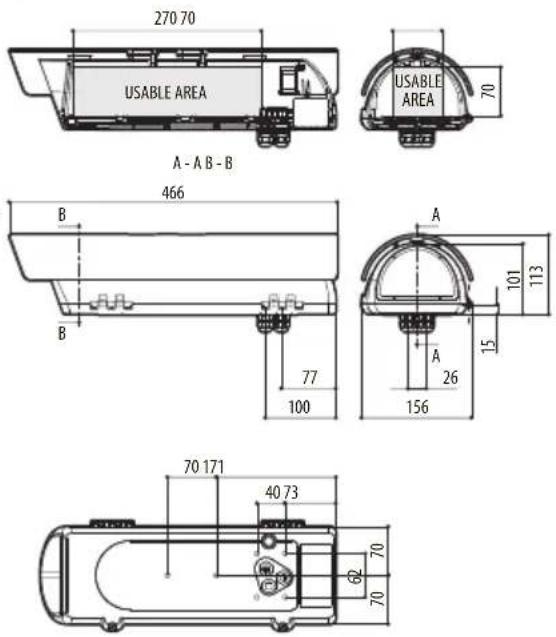
Fig. 15 VERSO.
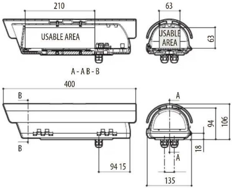
Fig. 16 VERSO COMPACT.
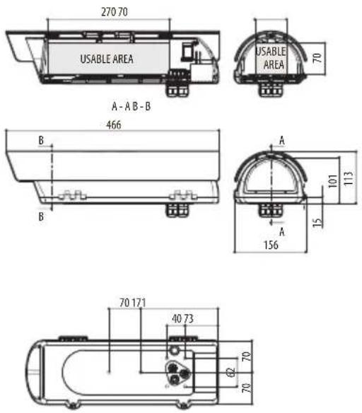
Fig. 17 VERSO POLAR.
VERSO, VERSO COMPACT, VERSO POLAR
natural_image
Technical line drawing of a mechanical enclosure or housing component (no text or symbols)Sommario
natural_image
Diagram of a mechanical component with a curved arrow indicating rotation or movement (no text or symbols present)Fig. 1

Fig. 2
Fig. 9
natural_image
Technical diagram of a mechanical assembly with structural supports and mounting brackets, showing two views of a bracket (no text or symbols present)Fig. 10
natural_image
Isometric line drawing of a rectangular electronic component with a connector and pin (no text or symbols)natural_image
Technical illustration of a mechanical assembly with a close-up view of a component being assembled (no text or symbols present)Fig. 12
natural_image
Technical illustration of an electronic device assembly showing internal components and a close-up view of the component (no text or symbols present)Fig. 13
7.3 Ventilatore
Fig. 14
8 Pulizia
natural_image
Technical line drawing of a mechanical enclosure or housing component (no text or symbols)Sommaire
4 Identification ....7
natural_image
Diagram of a mechanical component with a curved arrow indicating rotation or movement (no text or symbols present)Fig. 1

Fig. 2
Fig. 9
natural_image
Technical diagram of a mechanical assembly with structural supports and mounting brackets, showing two views of a beam or rail system (no text or symbols present)Fig. 10
natural_image
Isometric line drawing of a rectangular electronic component with a protruding rod (no text or symbols)natural_image
Technical illustration showing a mechanical assembly with a component being processed into a server chassis (no text or symbols visible)Fig. 12
natural_image
Technical illustration of an electronic device with a mounted sensor and wiring, showing internal components without any text or symbols.Fig. 13
7.3 Ventilateur
Fig. 14
8 Nettoyage
10.2.5 Certifications
10.3.5 Certifications
natural_image
Technical line drawing of a mechanical enclosure or housing component (no text or symbols)Inhaltsverzeichnis
1 Allgemeines 5
natural_image
Technical diagram of a mechanical component with an arrow indicating rotation or movement (no text or symbols present)Abb. 1

Abb. 2
Abb. 9
natural_image
Technical diagram of a mechanical assembly with structural supports and mounting brackets, showing two views of a bracket (no text or labels present)Abb. 10
natural_image
Isometric line drawing of a rectangular electronic component with a connector and pin (no text or symbols)natural_image
Technical illustration showing a mechanical assembly with a crane lifting a component, no visible text or symbolsAbb. 12
natural_image
Technical illustration of an electronic device with a close-up view showing internal components and wiring (no text or symbols)Abb. 13
73 Lüfter
Abb. 14
8 Reinigung
natural_image
Technical line drawing of a mechanical device with arched top and internal compartments (no text or symbols)natural_image
Diagram of a mechanical component with a curved arrow indicating rotation or movement (no text or symbols present)Рис. 1

Рис. 2
Рис. 9
natural_image
Technical diagram of a mechanical assembly with structural supports and mounting brackets, showing two views of a bracket (no text or labels present)Рис. 10
natural_image
Technical line drawing of a rectangular electronic component with a connector and leads (no text or symbols)natural_image
Technical illustration of a mechanical assembly with a close-up view of a device on a circuit board (no text or symbols visible)Рис. 12
natural_image
Technical illustration of an electronic device with a mounted sensor and wiring, showing internal components and wiring connections (no text or symbols)Рис. 13
7.3 Вентилятор
Рис. 14
8 Очистка

Headquarters Italy VIDEOTEC s.r.l.
Via Friuli, 6 - I-36015 Schio (VI) - Italy
Tel. +39 0445 697411 - Fax +39 0445 697414
Email: info@videotec.com
www.videotec.com
- VERSO, VERSO COMPACT, VERSO POLAR
- Contents
- About this manual....5
- Notes on copyright and information on trademarks....5
- Safety rules ....5
- Identification ....7
- Preparing the product for use....8
- Installation....9
- Accessories....13
- Cleaning 14
- Information on disposal and recycling 14
- Technical data.... 15
- VERSO COMPACT 16
- VERSO POLAR.... 17
- Technical drawings....18
- About this manual
- Typographical conventions
- DANGER!
- CAUTION!
- INFO
- Notes on copyright and information on trademarks
- Safety rules
- CAUTION! Device installation and maintaining must be performed by specialist technical staff only.
- Identification
- Product description and type designation
- VERSO
- VERSO COMPACT
- VERSO POLAR
- Product marking label
- Preparing the product for use
- Unpacking
- Contents
- Safely disposing of packaging material
- Preparatory work before installation
- Mounting the bracket
- Installation
- Housing opening
- How to install the camera
- Board description
- Connecting the power supply
- Type of cable
- Installation of the version with double filter for air renewal
- Desiccant bag
- Accessories
- Heater
- Heater installation
- Camera power supply
- Camera power supply installation
- Blower
- Blower installation
- Cleaning
- Cleaning the window and plastic parts
- Information on disposal and recycling
- Technical data
- VERSO
- General
- Mechanical
- Electrical
- Environment
- Certifications
- VERSO COMPACT
- General
- Mechanical
- Electrical
- Environment
- Certifications
- VERSO POLAR
- General
- Mechanical
- Electrical
- Environment
- Certifications
- Technical drawings
- Sommario
- Ventilatore
- Pulizia
- Sommaire
- Ventilateur
- Nettoyage
- Inhaltsverzeichnis
- Allgemeines 5
- Lüfter
- Reinigung
- Вентилятор
- Очистка
Brand : Videotec
Model : VERSO POLAR
Category : Camera case