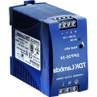
DPP30-24 - Power Supply TDK-Lambda - Free user manual and instructions
Find the device manual for free DPP30-24 TDK-Lambda in PDF.


| Product type | AC-DC switching power supply, DIN rail mount |
| Model | DPP30-24 |
| Brand | TDK-Lambda |
| Rated power | 30 W |
| Output voltage | 24 VDC |
| Output current | 1.25 A |
| Input voltage | 85 – 264 VAC, 47 – 63 Hz |
| Typical efficiency | 85 % |
| Dimensions (L x H x D) | 22.5 x 90 x 100 mm |
| Weight | 200 g |
| Protections | Short circuit, overvoltage, over temperature |
| Operating temperature | -25 °C to +71 °C |
| Protection rating | IP20 (IPX0 according to manual) |
| Safety standards | CE, UL 60950, EN 60950 |
| Ground connection | Mandatory, floating outputs possible |
| Internal fuse | Yes, not user-replaceable |
| Repairability | Not repairable by customer, mandatory return to factory |
| Maintenance and cleaning | No cleaning with liquids or solvents |
| LED indicator | Not specified in the manual, generally present |
| Voltage regulation | Typical load and line regulation < 1 % |
Frequently Asked Questions - DPP30-24 TDK-Lambda
User questions about DPP30-24 TDK-Lambda
0 question about this device. Answer the ones you know or ask your own.
Ask a new question about this device
Download the instructions for your Power Supply in PDF format for free! Find your manual DPP30-24 - TDK-Lambda and take your electronic device back in hand. On this page are published all the documents necessary for the use of your device. DPP30-24 by TDK-Lambda.
USER MANUAL DPP30-24 TDK-Lambda
General Safety Instructions:
ENGLISH

READ SAFETY INSTRUCTIONS
Servicing:
These products are not customer serviceable. TDK-Lambda UK LTD. and their authorised agents only are permitted to carry out repairs.
Critical Components:
These products are not authorised for use as critical components in nuclear control systems, life support systems or equipment for use in hazardous environments without the express written approval of the Managing Director of TDK-Lambda EMEA.
Product Usage:
These products are designed for use within a host equipment which restricts access to authorised competent personnel.
Environmental:
These products are IPX0, and therefore chemicals/solvents, cleaning agents and other liquids must not be used.
Environment:
This power supply is a switch mode power supply for use in applications within a Pollution Degree 2, overvoltage category II environment. Material Group IIIb PCB's are used within it.
Output Loading:
The output power taken from the power supply must not exceed the rating stated on the power supply label, except as stated in the product limitations in this handbook.
Input Parameters:
This product must be operated within the input parameters stated in the product limitations in this handbook.
End of Life Disposal:
The unit contains components that require special disposal. Make sure that the unit is properly disposed of at the end of its service life and in accordance with local regulations.

RISK OF ELECTRIC SHOCK
High Voltage Warning:
Dangerous voltages are present within the power supply. The professional installer must protect service personnel from inadvertent contact with these dangerous voltages in the end equipment.
This product must be reliably earthed and professionally installed in accordance with the prevailing local electrical wiring regulations and safety standards.
The (+) or (-) output(s) can be earthed or left floating.
An internal fuse protects the unit and must not be replaced by the user. In case of internal defect, the unit must be returned to TDK-Lambda UK LTD or one of their authorised agents.
HOT SURFACE
External Hot Surfaces:
In accordance with local regulations for Health and Safety at work, manufacturers have an obligation to protect service engineers as well as users. In order to comply with this, a label must be fitted to these products which is clearly visible to service personnel accessing the overall equipment, and which legibly warns that surfaces of these products may be hot and must not be touched when the products are in operation.
The ventilation openings on these products must not be impeded. Ensure that there is at least 25mm spacing between any obstruction and the ventilation openings.
The unit cover/chassis is designed to protect skilled personnel from hazards. They must not be used as part of the external covers of any equipment where they may be accessible to operators, since under full load conditions, part or parts of the unit chassis may reach temperatures in excess of those considered safe for operator access.
Attention-Danger haute tension:
SOLO PER I PRODOTTI A CA-CC

RISCHIO DI SCOSSA ELETTRICA
APENAS PRODUTOS CA-CC

RISCO DE CHOQUE ELÉCTRICO
Special Safety Instructions
Standard Specific Safety Instructions:
Whilst all individual outputs are classed as SELV outputs in accordance with the standard IEC/EN/UL/CSA60950-1 (<60Vdc or 42.4V peak), seriesed combinations of these outputs may exceed these values and become hazardous output voltages.
If the equipment is used in a manner not specified by the manufacturer, the protection provided by the equipment may be impaired.
Environmental Specifications:
| Description Operation Storage | ||
| Use Indoor -Temperature -25°C - +71°C (derating at 2.5%/°C from 61°C) -25°C - +85°C | ||
| Humidity 20 - 95% RH, non-condensing 20 - 95% RH, non- | condensing | |
| Altitude 2000M | 4850m (IEC60068-2-13) | |
| Orientation | See Fig 1 | ALL |
| Material Group | IIIb | |
| Pollution Degree | 2 | |
| Class | I | |
Level of Insulation:
Dielectric Strength testing is carried out as follows:
Primary mains circuit to earth: - 1500KVAC, 2121VDC
Primary mains circuits to secondary: 3kVAC, 4142VDC*
*This test is not possible with Y capacitors fitted to the unit as damage to these capacitors will occur. It is also necessary to short circuit the output together and to earth.
Safety Approvals:
UL508
UL/cUL60950-1 (2 ^nd Edition)
IEC / EN60950-1(2 ^nd Edition)
CE marking when applied to any DPP15 to100-xx product indicates compliance with the Low Voltage Directive (2006/95/EC) in that it complies with EN60950-1 ( 2^nd Edition).
Fusing: Internal fuses (F1): Single fuse in the L line, T3.15AH, 250V, 5x20mm.
Symbols:


AC
EARTH

N - Neutral

L - Live
If the earth terminal of the DPP15 to 100-XX-1 PSU is connected to the main incoming earth conductor of the end equipment, the installer must cover the earth symbol with a label bearing the earth symbol of IEC60417-5019.
Input Parameters:
| Decsription Operation | |
| Nominal input voltage 85 -264VAc | |
| Input frequency range 47 – 63Hz | |
| Maximum inrush current 55A* |
* see datasheet for specific models
Output Parameters:
| Model | Vout (V) | Adjustment | range (V) | Output current (A) |
| DPP15-24 | 24 | 22.5 – 28.5 | 0.63 | |
| DPP25-5 | 5 | 5 – 6 | 5 | |
| DPP30-12 | 12 | 9.9 – 12.1 | 2.5 | |
| DPP30-24 | 24 | 22.5 – 28.5 | 1.3 | |
| DPP50-15 | 15 | 11.9 – 15.1 | 3.4 | |
| DPP50-24 | 24 | 22.5 – 28.5 | 2.1 | |
| DPP50-48 | 48 | 48 – 56 | 1.05 | |
| DPP100-24 | 24 | 22.5 – 28.5 | 4.2 |
Adjusting output voltage beyond the stated range may cause overvoltage protection (OVP) to operate, whereby the output will latch off. To reset for normal operation simply adjust the potentiometer to reduce the output voltage to within its range and cycle the input off then on.
All outputs are SELV except under the following circumstance: Outputs connected in series are non-SELV if the total output voltage exceeds 60Vdc
If the total voltage of outputs connected in series exceed the 60Vdc SELV limit then all outputs must be considered non-SELV.
Non-SELV outputs are hazardous and must not be made user accessible. Consideration must be given to service engineers making inadvertent contact with the output terminals in the end equipment.
All outputs have functional spacing to earth, and due consideration must be given to this in the end product design.
Cooling for unit
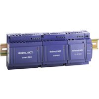
The unit must be mounted on a DIN rail and must not be inverted, the output connection uppermost.
Fig. 1
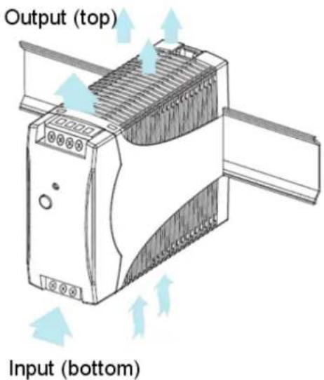
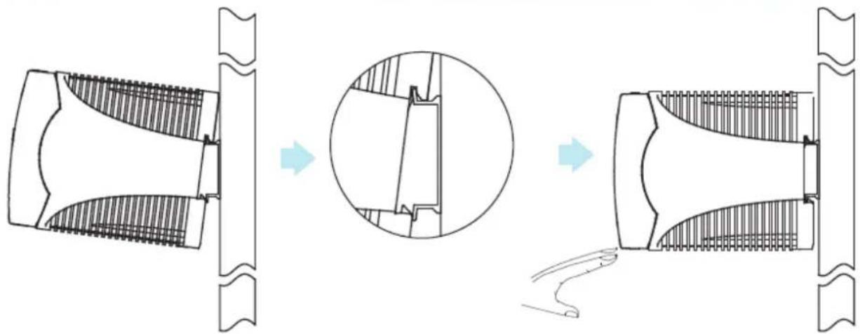
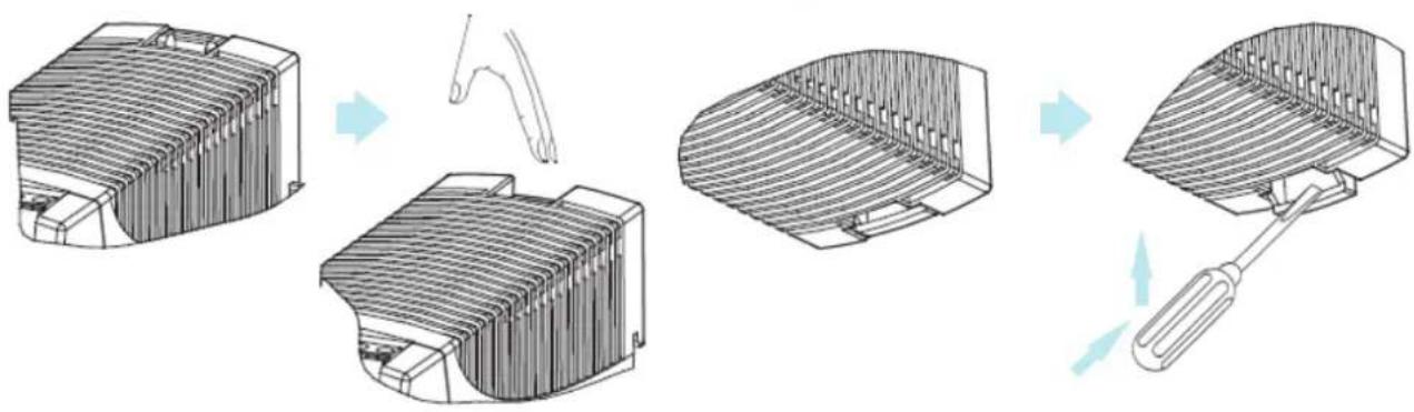
Fig. 2 Placement
natural_image
Technical diagram showing three stages of a mechanical component with cross-sectional views and internal details (no text or labels)Fig. 3 Removal
natural_image
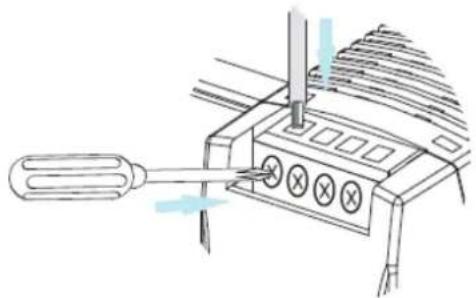
Diagram showing four steps of a mechanical device with a tool, no text or symbols presentStandard screw type connection: AWG26 to AWG12 can be used, maximum torque rating connector is 0.56Nm (5 Pound-inches).
natural_image
Line drawing of a mechanical device with a tool inserted, showing internal components and a blue arrow indicating motion (no text or symbols)Mechanical Outline Drawings:
Outline drawing DPP15 Series
![mm [inch] 22.8 [0.9] 2 1 + - 24 VDC / 0.63A DC ON Vout ADJ. TDK-Lambda 100-240VAC 0.4A 47-63Hz NL 3 4 5 96.7 [3.81]](/content/2026/04/719346/images/1bc86e7197e3a19c37c4d5b167540acbae34e4b505e3aefc63bb53447ecb2e08.jpg)
Outline drawing DPP25-DPP50 Series
![mm [inch] 45 [1.77] 4 3 2 1 75 [2.95] 91 [3.58] TDK·Lambda 100-240VAC 0/63A 47-63Hz ⊕ N L ⊕ ⊕ ⊕ ⊕ + + - - S VDC / SA DC ON Vout ADJ. 5 6 7](/content/2026/04/719346/images/67537104063b2f514dc61bbaabefec8447d770a33354c711484eec82562ebb68.jpg)
Outline drawing DPP100 Series
![mm [inch] 72.5 [2.86] 4 3 2 1 Single Parallel + + - 24 VDC / 4,2A DC ON Vout ADJ, 75 [2.95] TDK·Lambda 115/230VAC 2.2/1.2A 47-63Hz ⊕ N L 5 6 7 96.7 [3.81]](/content/2026/04/719346/images/28dda64e53e507d13cbbfa3dd699e12e2b68324cec756d5abce5be255965e553.jpg)
| Pin number DPP15 DPP25 - 50 DPP100 | |||
| 1 -DC Output -DC Output -DC Output | |||
| 2 +DC Output -DC Output -DC Output | |||
| 3 Earth Input +DC Output +DC Output | |||
| 4 Neutral AC Input +DC Output +DC Output | |||
| 5 | Live AC input | Earth Input | Earth Input |
| 6 | Not present | Neutral AC Input | Neutral AC Input |
| 7 | Not present | Live AC input | Live AC input |
| Potentiometer | Vout Adjust Vout Adjust | Vout Adjust | |
| Green Led (Lit) | DC ON | DC ON | DC ON |
TDK·Lambda
TDK-Lambda UK Ltd
Kingsley Avenue, Ilfracombe
Devon, EX34 8ES
Telephone - Sales and Service +44 (0)1271 856666
Head Office and Works +44 (0)1271 856600
Facsimile +44 (0)1271 864894
- General Safety Instructions:
- Servicing:
- Critical Components:
- Product Usage:
- Environmental:
- Environment:
- Output Loading:
- Input Parameters:
- End of Life Disposal:
- High Voltage Warning:
- HOT SURFACE
- External Hot Surfaces:
- Attention-Danger haute tension:
- SOLO PER I PRODOTTI A CA-CC
- APENAS PRODUTOS CA-CC
- Special Safety Instructions
- Standard Specific Safety Instructions:
- Environmental Specifications:
- Level of Insulation:
- Safety Approvals:
- Symbols:
- Output Parameters:
- Cooling for unit
- TDK·Lambda
Brand : TDK-Lambda
Model : DPP30-24
Category : Power Supply