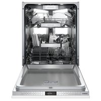
DF481701F - Washing machine GAGGENAU - Free user manual and instructions
Find the device manual for free DF481701F GAGGENAU in PDF.


| Product type | Built-in dishwasher |
| Brand | Gaggenau |
| Model | DF481701F |
| Voltage | 120 V |
| Frequency | 60 Hz |
| Current | 12 A |
| Maximum power | 1440 W |
| Water pressure | 15 - 145 psi (1 - 10 bars) |
| Water temperature | 120 °F (49 °C) recommended, max 140 °F (60 °C) |
| Minimum opening height | 34 1/8 in (867 mm) |
| Minimum opening width | 23 5/8 in (600 mm) |
| Maximum drain hose length | 92 in (2337 mm) without extension, 150 in (380 cm) with extension |
| Minimum drain loop height | 33 in (84 cm) from floor |
| Panel weight | 10 - 24 lb |
| Leak protection system | AquaStop® Plus with damage warranty |
| Mounting type | Top or side (Vario Hinge) |
| Panel material | Wood or other, drillable |
| Required tools | Drill, Phillips and flathead screwdrivers, Torx T-15/T-20, level, etc. |
| Included parts | Drilling template, flathead screwdriver, open-end wrench, adjustable wrench, emergency door handle, level, screws, hook-and-loop strips |
| Safety instructions | Cut water and power supply before installation; do not use extension cord; grounding mandatory |
| Protection rating | Compliant with NSF/ANSI 184 (household use) |
| Customer service | 1-877-442-4436 (USA) ; www.gaggenau.com |
Frequently Asked Questions - DF481701F GAGGENAU
User questions about DF481701F GAGGENAU
0 question about this device. Answer the ones you know or ask your own.
Ask a new question about this device
Download the instructions for your Washing machine in PDF format for free! Find your manual DF481701F - GAGGENAU and take your electronic device back in hand. On this page are published all the documents necessary for the use of your device. DF481701F by GAGGENAU.
USER MANUAL DF481701F GAGGENAU
en-us Installation Instructions
1.1 Safety definitions.... 3
1.2 General information...... 3
1.3 Safe Installation 4
1.4 Electrical safety...... 4
1.5 State of California Proposition 65 Warnings.... 6
2 Before you begin.... 7
2.1 Inspect the Dishwasher...... 7
2.2 Parts Included.... 7
2.3 Tools and Parts Needed 8
2.4 Pre-install Checklist.... 9
2.5 Electrical Requirements ...... 9
2.6 Cabinet Requirements ...... 10
3 Installation Preparation ...... 10
4 Installation Procedure ...... 11
4.1 Attach Steam Fender 11
4.2 Pre-level the Dishwasher ..... 11
4.3 Attach Power Cord.... 12
4.4 Mounting Brackets Vario
Hinge 12
4.5 Attaching the Apron.... 13
4.6 Prepare the Panel 14
4.7 Attach Panel Mounting
Brackets.... 15
4.8 Attach the Panel and Deco Strips 16
4.9 Install Dishwasher in Cabinet Space.... 17
4.10 Level the Dishwasher...... 18
4.11 Secure Top and Side Mount.... 19
4.12 Opening the door 20
4.13 Adjust door opening 20
4.14 Attach the 2-part Toe Panel .... 20
4.15 Attach the Outer Toe Panel..... 21
5.1 Installing the Water Inlet Connection.... 22
5.2 Installing the Drain Connection.... 23
5.3 Electrical Connection and Test Cycle.... 24
5 Dishwasher Connection ..... 22
6 Customer Service 24
6.1 Model number (E-Nr.) and production number (FD) ..... 25
6.2 AquaStop® Plus Pledge...... 25
Read all of the instructions carefully before using the appliance. In order to reduce the risk of fire, electric shocks and personal injuries when using the appliance, follow the basic safety precautions, including the following safety instructions.
1.1 Safety definitions
Here you can find explanations of the safety signal words used in this manual.

WARNING
This indicates that death or serious injuries may occur as a result of non-observance of this warning.

CAUTION
This indicates that minor or moderate injuries may occur as a result of non-observance of this warning.
NOTICE:
This indicates that damage to the appliance or property may occur as a result of non-compliance with this advisory.
Note: This alerts you to important information and/or tips.
1.2 General information
To reduce the risk of fire, electrical shock, or serious injury, observe the following.
■ This appliance is provided with installation instructions and this use and care manual. Read and understand all instructions before using the appliance.
- Keep the manual and the product information in a safe place for future reference or for the next owner.
■ Do not connect the appliance if it has been damaged in transit.
■ Product damage and/or injury could result from the use of unqualified service technicians or non-original parts. All repairs should be performed by an authorized service provider using only original equipment factory replacement parts.
■ NSF/ANSI 184 Certified residential dishwashers are not intended for licensed food establishments.
1.3 Safe Installation
Follow these safety instructions when installing the appliance.
■ These instructions are intended for use by qualified installers only. The dishwasher must be installed by a qualified technician or installer.
■ The dishwasher drain hose must be installed with a portion of it at least 33" (84 cm) off the floor; otherwise the dishwasher may not drain properly.
■ This dishwasher is not for outdoor use. It is intended for indoor residential use only, and should not be used in commercial food service establishments.
■ This dishwasher is designed to be enclosed on the top and both sides by cabinetry.
■ NEW INSTALLATION - If the dishwasher is a new installation, ensure all connections are properly made before the dishwasher is moved into place.
■ REPLACEMENT - If the dishwasher is replacing another dishwasher, check the existing dishwasher connections for compatibility with the new dishwasher, and replace parts as necessary.
■ This appliance has been found to be in compliance with CAN/CSA-C22.2 No. 167/UL 749. It is the responsibility of the owner and the installer to determine if additional requirements and standards apply in specific installations.
WARNING
Under certain conditions, hydrogen gas may be produced in a hot water system that has not been used for two weeks or more. Hydrogen gas is explosive.
Before using a dishwasher that is connected to a hot water system that has been unused for two weeks or longer, turn on all hot water faucets and let the water flow from each for several minutes. This will release any accumulated hydrogen gas. As the gas is explosive, do not smoke or use an open flame during this time.
1.4 Electrical safety
Follow these safety instructions to avoid electrical shock.
■ The dishwasher must be properly grounded before operating. This appliance must be connected to a grounded metal permanent wiring system or an equipment grounding conductor must be run with the circuit conductors and connected to the equipment grounding terminal or lead on the dishwasher.
■ DO NOT use an extension cord
■ DO NOT reuse an old power cord; only use the cord provided.
■ Make sure that the dishwasher is connected to a suitable ground in compliance with all local codes or, in the absence of a local code, with the NATIONAL ELECTRICAL CODE in the United States or the CANADIAN ELECTRIC CODE C22.1-latest edition in Canada as well as any provincial/state or municipal or local codes that apply
■ Installations requiring hard wiring and terminal block - The accessory terminal block/junction box model, SMZPCJB1UC, designed for permanent wire connection, is not included but can be ordered through Customer Service by calling 1-800-944-2904. Follow the instructions included with the kit.
WARNING
Avoid Electrical Shock
▶ Do not work on an energized circuit. Doing so could result in serious injury or death. Only qualified electricians should perform electrical work. Do not attempt any work on the dishwasher electric supply circuit until you are certain the circuit is de-energized.
▶ To avoid possible injury or property damage, care should be exercised when the dishwasher is installed or removed to reduce the likelihood of damage to the power cord.
WARNING
Avoid Fire Hazard
▶ Make sure electrical work is properly installed and checked by qualified electricians.
▶ Make sure there are no loose electrical connections. Make sure all electrical connections are properly made. Loose and improperly installed electrical connections can result in overheating!
Wall outlet connections
▶ Only use the provided power cord for wall socket connections.
▶ DO NOT attach an extension cord or any type of modified cord or adapter with this appliance.
▶ DO NOT cut or splice the power cord.
▶ DO NOT alter the power cord in any way.
Permanent wire connections (in addition to the warnings above)
▶ Only use the junction box power cord, sold as Accessory kit #SMZPCJB1UC.
▶ Carefully review the terminal block installation instructions.
▶ DO NOT remove, alter or bypass the terminal block.
1.5 State of California Proposition 65 Warnings
This product may contain a chemical known to the State of California, which can cause cancer or reproductive harm. Therefore, the packaging of your product may bear the following label as required by California:
STATE OF CALIFORNIA PROPOSITION 65 WARNING:

WARNING
Cancer and Reproductive Harm - www.P65Warnings.ca.gov
2 Before you begin
Read these instructions before you begin to install your appliance.
2.1 Inspect the Dishwasher
After unpacking the dishwasher and prior to installation, thoroughly inspect the dishwasher for possible freight or cosmetic damage. Report any damage immediately. Cosmetic defects must be reported within 30 days of installation. NOTE: Do not discard any bags or items that come with the original package until after the entire installation has been completed.
2.2 Parts Included
After unpacking all the parts, check for any damage in transit or missing parts.
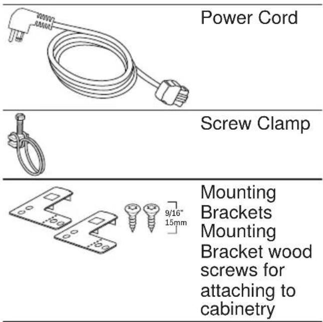
| 5/8" 17mm Toe Panel *depending on your model Toe Panel Screws | |
| 1/2" 13mm | |
| Steam fender | |
| Water Supply Adaptor | |
| Rubber Drain Hose Adaptor | |
| Mounting Brackets and screws for fully integrated door panel | |
| Toe Panel Brackets | |
| Side Mount Force Distributors and Screws |
en-us Before you begin
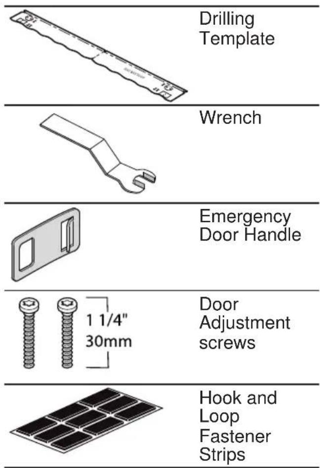
2.3 Tools and Parts Needed
Gather these tools and additional parts before beginning the installation of your appliance.
Tools
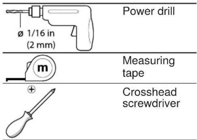
| Flat screwdriver | |
| Adjustable wrench | |
| Level | |
| T-15 Star- head screwdriver | |
| T-20 Star- head screwdriver | |
| Jigsaw | |
| Pencil | |
| Steel Square |
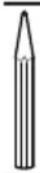
Center Punch
Parts
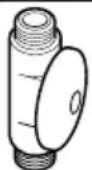
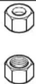

Shut-off valve and fittings appropriate for hot water supply line.
2.4 Pre-install Checklist
Ensure that the following requirements are met when planning the installation of your appliance.

WARNING
Avoid Scalding or Electric Shock Hazard
- Make sure the water supply and electrical supply are shut off before installation or service.
- Do not allow the electrical and supply lines to touch.
■ Select a location as close to the sink as possible for easy access to water supply and drain lines. - Be sure the unit is installed close enough to the sink so the drain hose length does not exceed 92" (2337 mm) and so that a portion of the drain hose is raised at least 33" above the floor level.
■ Ensure that the enclosure is square and the opening is at least 34 1/8" (867 mm) high and 23 5/8" (600 mm) wide. - Check that the opening in the cabinet is large enough for routing the electric cable, water line, and drain hose, and if not, create a new
opening. See
→ "Installation Preparation", Page 10
■ If the opening is wood, be sure it is sanded smooth. If it is metal, be sure it is covered by a protective gasket.
■ Be sure that your water heater set at 120^ F ( 49^ C) and the water pressure measures at 15-145 psi (1-10 bar)
■ Determine the mounting method based on the dishwasher model and counter-top type. See → "Mounting Brackets Vario Hinge", Page 12.
■ Only use the included hardware for the installation. If you are replacing a dishwasher, dispose of old hose and other equipment properly.
■ To avoid scratching the floor, have floor protection ready for when the dishwasher will be slid into the cabinet.
2.5 Electrical Requirements
Ensure that the following electrical requirements are met.
Dishwasher electrical rating
| Volts 120 |
| Hertz 60 |
| Amperes 12 |
| Watts 1,440 (max) |
Electrical Supply
The customer has the responsibility of ensuring that the dishwasher electrical installation is in compliance with all national and local electrical codes and ordinances. The dishwasher is
en-us Installation Preparation
designed for an electrical supply of 120V, 60 Hz, AC, connected to a dishwasher-dedicated, properly grounded electrical circuit with a fuse or breaker rated 15 or 20 amps.
2.6 Cabinet Requirements
Ensure that the cabinet space for the installation meets the required dimensions.
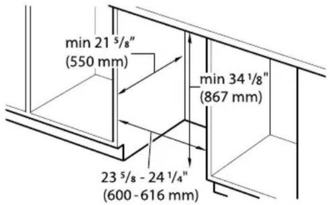
If the dishwasher is to be installed in a corner, ensure that there is adequate clearance to open the door as shown.
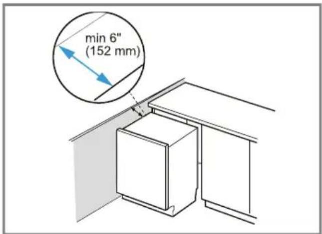
3 Installation Preparation
After locating the proper place for your dishwasher, create an opening to allow for water, drain and electrical lines on the appropriate side.
- Cut a rectangular hole 2.5" x 3.5" in the rear corner on the sink facing side.
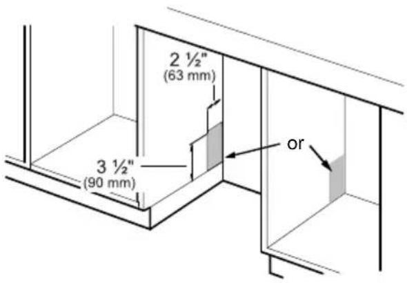
If the opening is made through wood, sand it smooth. If the opening is made through metal, use the Edge Protector with Power Cord clips Kit SMZEPCC1UC.
- Remove the rubber apron from the top of the dishwasher.
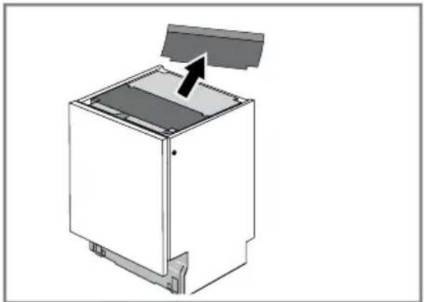
natural_image
Diagram of a white appliance with a black arrow pointing to the lid area, showing internal components and mounting base (no text or symbols)- Remove the hose clip from the back of the dishwasher.
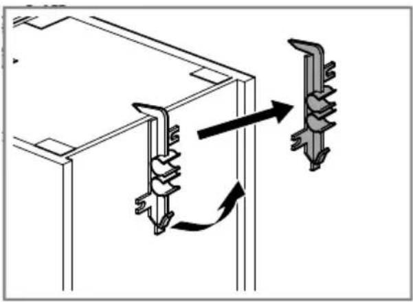
natural_image
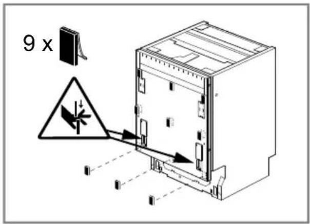
Diagram showing two electrical connector assemblies with arrows indicating rotation or assembly (no text or symbols)4. ⚠️ WARNING - Risk of
crushing! Pinch Point Hazard
- Keep fingers out of openings on the inner door. Sliding parts can pinch fingers.
Add the 9 pieces of hook and loop fasteners to the outer door.
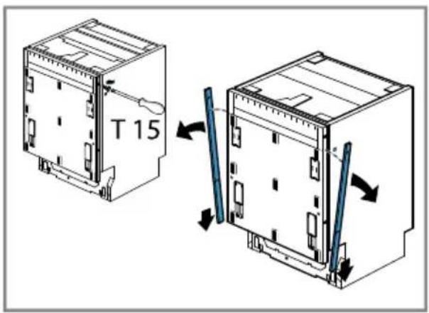
- Remove the side deco strips and reserve the strips and screws for later.
4 Installation Procedure
Follow these instructions to install the dishwasher.
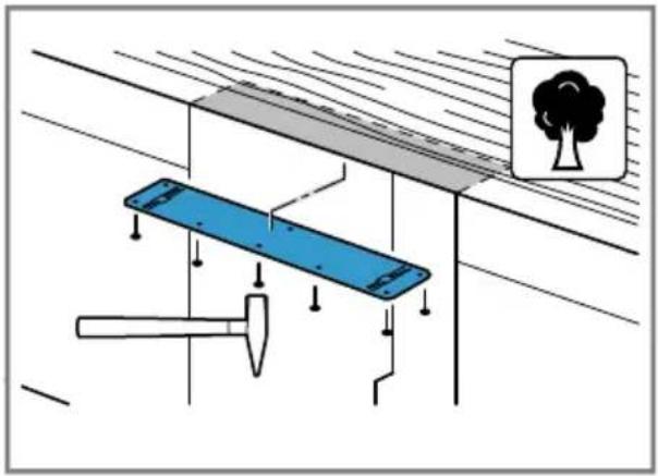
4.1 Attach Steam Fender
- Attach the steam fender to the underside of the counter with the included nails.
natural_image
Diagram showing a blue structural beam supported by a hammer and a tree, with no visible text or symbols.4.2 Pre-level the Dishwasher
Set the dishwasher to the correct height before it goes into the cabinet.
- Measure the height of the cabinet opening.
en-us Installation Procedure
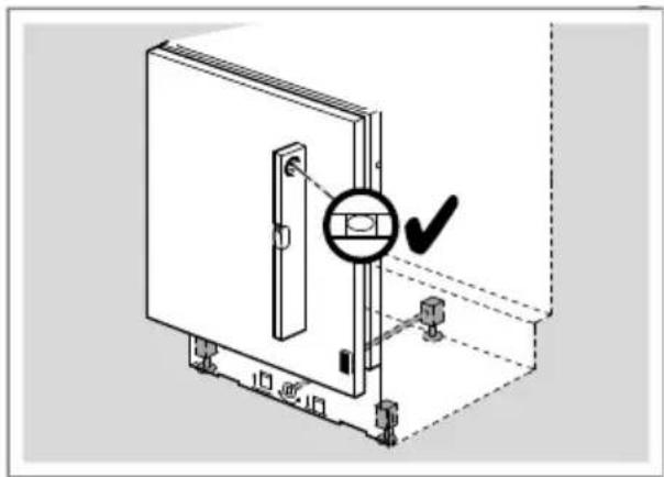
- Raise the front of the dishwasher to approximately 1/2" lower than the height of the opening by turning the feet clockwise.
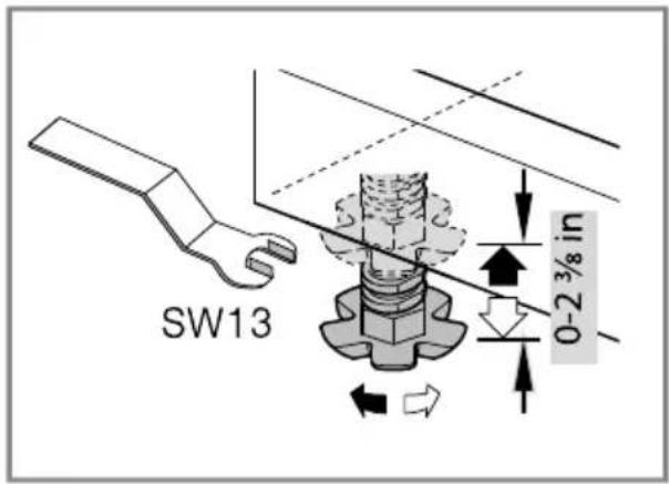
You can raise the rear foot after the unit is in the cabinet opening.
- Use a level on the top front to see that both feet are even.
natural_image
Technical diagram of a door assembly with a circular component and mounting base (no text or symbols)4.3 Attach Power Cord
- Plug the end of the supply cord into the back of the dishwasher.
- Be sure to push it all the way in until fully seated.
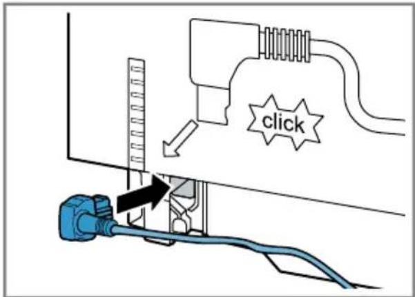
The outlet for the power supply cord should be located in a cabinet or wall adjacent to the dishwasher cabinet.
Do not plug dishwasher into the wall outlet until all the steps of the installation are complete.
Notes
■ If you require a permanent wiring connection, order kit junction box accessory kit SMZPCJB1UC.
■ If local electrical codes require clips to secure the power cord wire to the dishwasher, use accessory kit SMZEPCC1UC.
4.4 Mounting Brackets Vario Hinge
Before installing the supplied mounting brackets, decide which method of securing the dishwasher into its enclosure will be used, top (wood or porous material) or side (stone or solid surface). Once the mounting brackets are installed on the dishwasher,
removing them is difficult and will damage the mounting brackets and the dishwasher. If you have a Fully Integrated Panel, do not attach mounting brackets until after attaching the panel to the door.

WARNING
Avoid tip over hazard
- Do not use the dishwasher until it is completely installed. When opening the door on an uninstalled dishwasher, carefully open the door while supporting the rear of the unit. Failure to follow this warning can result in serious injury.
Top and Side Mount
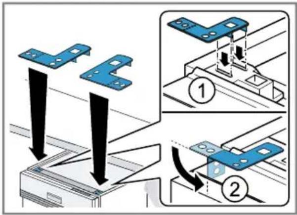
For openings wider than 23 5/8" (600 mm), use the metal mounting brackets. Top mount is for wood or other materials that can easily be drilled into. Side mount is for stone countertops or another hard material that cannot easily be drilled. Both use the same mounting brackets, but the difference is the screw placement.
- Orient the mounting brackets as shown and position the tabs into openings on the dishwasher's front corners.
- For side mount, bend the brackets down at the perforation.
Side Mount Force Distributor
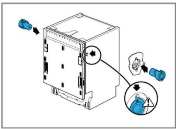
The side mount force distributors are for cabinet openings that are 23 5/8".
- Insert a side mount force distributor into the opening in each side. Make sure it is flush with the dishwasher.
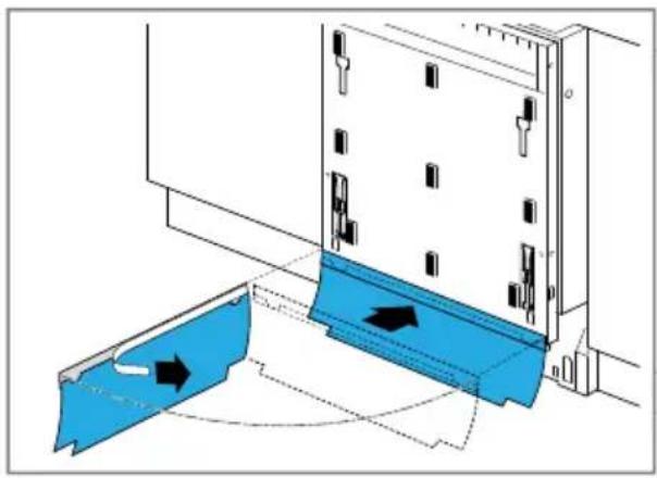
4.5 Attaching the Apron
- Remove tape covering adhesive strip on the rubber apron.
en-us Installation Procedure
- Adhere the apron to the front of the dishwasher.
natural_image
Diagram of a device with blue plastic components and directional arrows indicating movement or flow (no text or symbols)4.6 Prepare the Panel

WARNING
Pinch Point Hazard
- Keep fingers out of openings on the inner door. Sliding parts can pinch fingers.
Note: The door panel should weight between 10 and 24 pounds. If it is heavier, call Customer Service.
- Remove plastic inserts from the slots on the outer door.
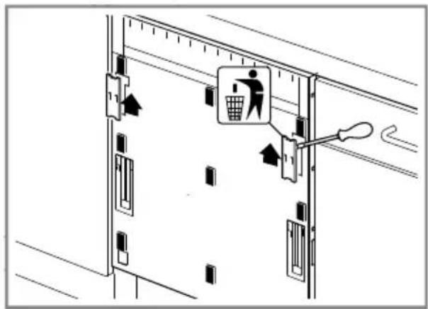
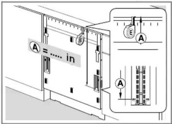
- Measure from the top of the cabinet opening to the base of the bracket insertion.
- Record that distance (A).
-
Measure that same distance (A) on the door panel starting at the top of the panel.
-
Use the included template to mark the center of the panel.
- Draw a vertical line down the center of the panel.
- Draw a horizontal line across at A.
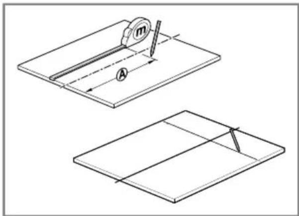
- Line the template up with the horizontal line and mark the dots for I.
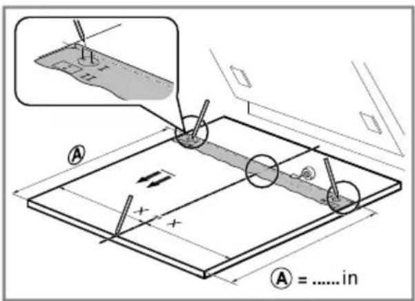
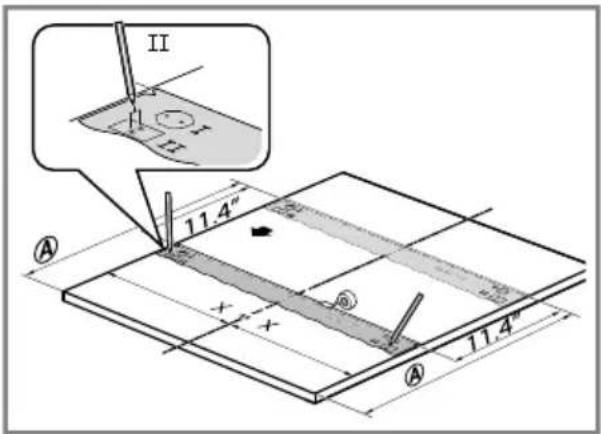
- Move the template 11.4" (290 mm) from line A.
- Draw another line and mark the dots at II.
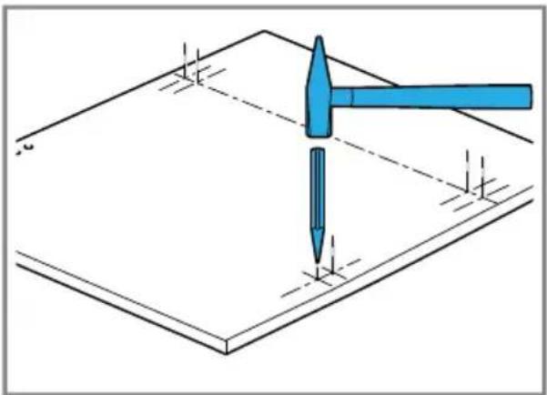
- Make pilot holes with a hammer and a center punch.
natural_image
Diagram showing a hammer striking a surface with a screwdriver, no text or symbols present4.7 Attach Panel Mounting Brackets
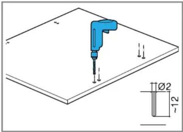
- Drill 2/3 of the way through the panel.
natural_image
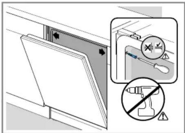
Technical diagram showing a blue tool inserted into a flat plate with a small inset detail labeled ∅2 and ~12 (no text or symbols beyond basic geometry)- Attach the mounting brackets to the panel with the screws provided.
- Attach by hand; do NOT use a power drill.
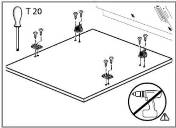
4.8 Attach the Panel and Deco Strips
- If your dishwasher requires a handle, attach it before mounting the panel to the dishwasher.
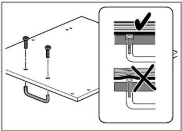
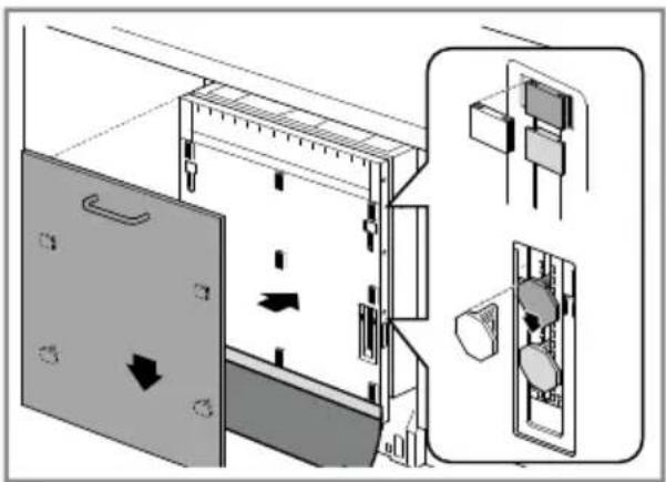
- Attach the panel to the dishwasher by aligning the brackets into the hinges and sliding into place.
natural_image
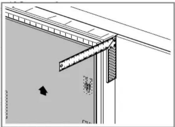
Diagram of a refrigerator interior showing door, drawer, and storage compartments with directional arrows (no text or labels)- Make sure the dishwasher is square to the counter.
natural_image
Architectural detail drawing showing a door frame with a ruler and directional arrow (no text or symbols)- To match the heights of the cabinetry, adjust the panel if necessary.
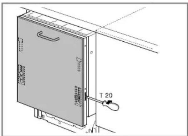
- Align the deco strips to the sides.
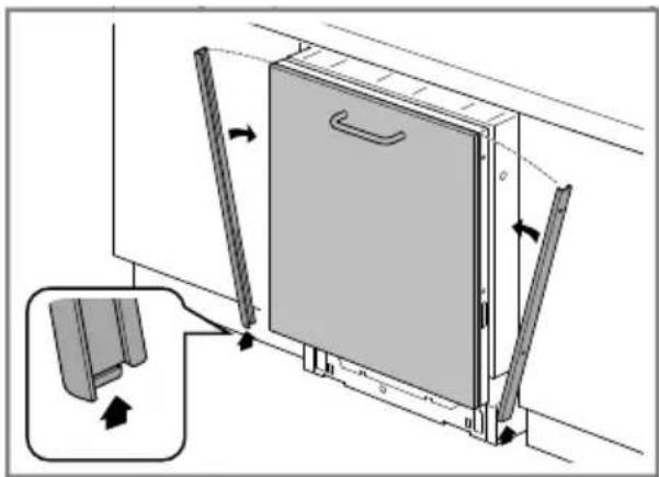
natural_image
Diagram of a door frame assembly with directional arrows indicating movement, showing structural components and mounting bracket (no text or symbols)- With a torx 15, re-insert the screws that were removed earlier.
- Do not use a power drill.
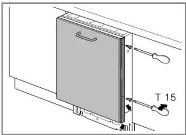
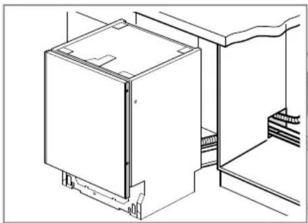
4.9 Install Dishwasher in Cabinet Space
To avoid scratching the floor, use floor protection and caution when sliding the dishwasher into the cabinet.
NOTICE:
Avoid Hose Kinks
- Be careful while pushing dishwasher in. The hoses can fold, kink or break, potentially causing an obstruction or leak.
- Feed the power cord and hoses through the low hole in the cabinet.
natural_image
Technical line drawing of a cabinet or enclosure structure with mounting brackets and structural details (no text or symbols)- Carefully and slowly push the dishwasher into the cabinet space.
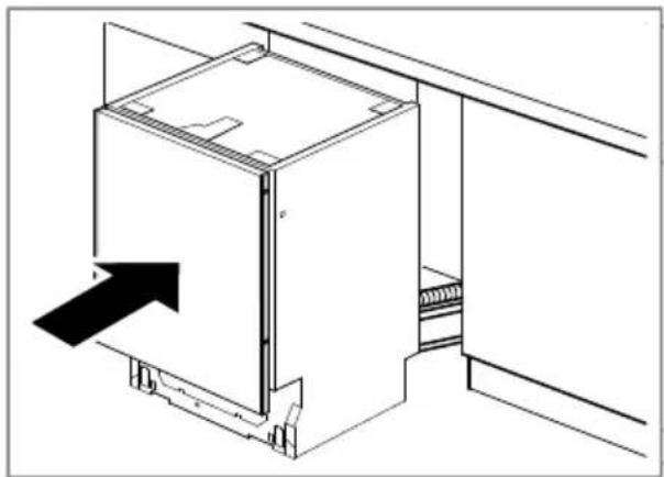
natural_image
Technical line drawing of a refrigerator with an arrow indicating airflow direction (no text or symbols)- Reach into adjacent cabinet and pull hoses and excess power cord through completely so they do not get kinked.
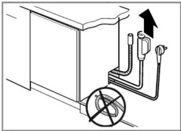
natural_image
Diagram of a piping system with a circular component and upward arrow, no text or symbols present- Finally, push the unit in until flush with cabinet door.
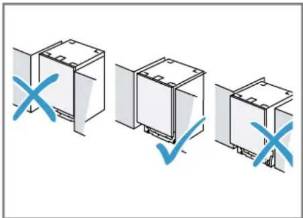
- Center the dishwasher in the opening.
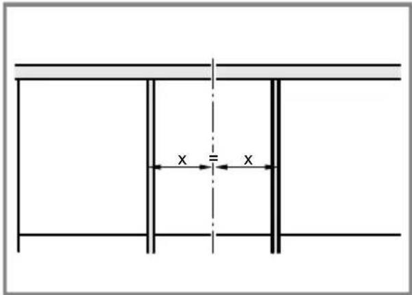
4.10 Level the Dishwasher
Now that the dishwasher is in the cabinet, check the levels again.
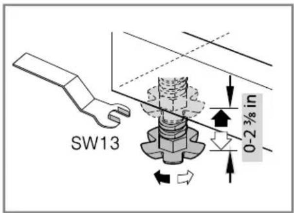
- Level side to side by turning feet clockwise to raise or counterclockwise to lower front.
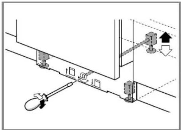
- Level front to back by turning center screw clockwise to raise or counterclockwise to lower the back.
natural_image
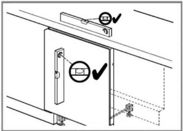
Technical diagram of a mechanical assembly with no visible text or symbols- Use a level to check that your dishwasher is level.
- Ensure that the countertop is level and adjust the dishwasher to the countertop.
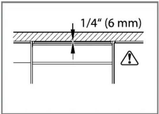
- Make sure the top of the door is no less than 1/4" (6 mm) from the underside of the counter.
4.11 Secure Top and Side Mount
- For top mount, drive the mounting screws through the holes in the bracket into the countertop.

natural_image
Technical diagram of a mechanical assembly with two inset views showing blue screw fasteners (no text or symbols present)- For side mount, drive the mounting screws through the holes in the sides of the cabinetry.
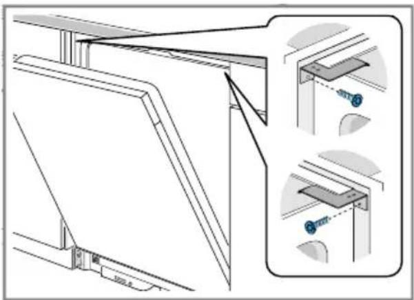
natural_image
Technical line drawing of a structural assembly with two views and mounting brackets (no text or symbols)- If using the force distributor side mounts, first remove the cutlery rack.
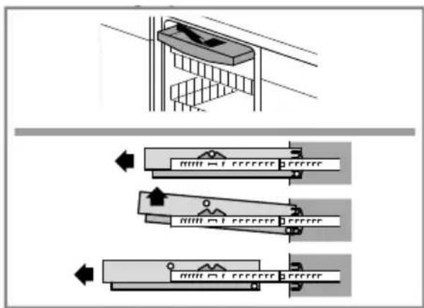
- Drive the mounting screws through the holes inside the dishwasher.
- Re-insert the cutlery rack.
4.12 Opening the door
- To open the dishwasher, use the included emergency door opening tool.
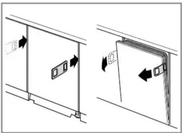
natural_image
Diagram showing two mechanical assembly steps with arrows indicating motion direction (no text or symbols)4.13 Adjust door opening
Requirement: If you installed a heavy wooden door, adjust the opening.
- Insert the included screws at the base on both sides.
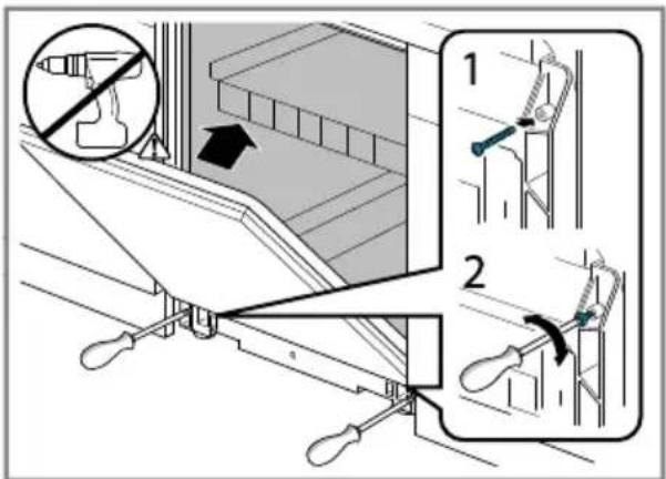
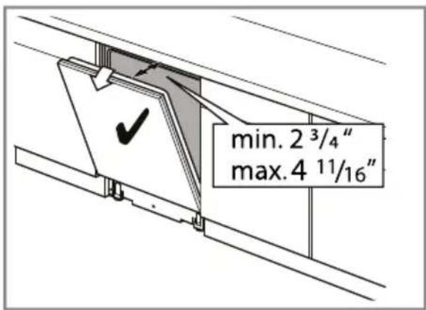
- Adjust the tension so the door rests open between 2 3/4 in. (70 mm) and 4 11/16 in.(120 mm).
4.14 Attach the 2-part Toe Panel
-
If your dishwasher has a rubber apron, install the 2-part toe panel behind the apron.
-
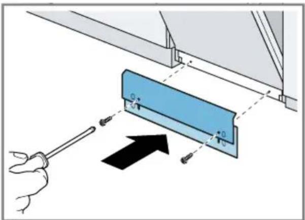
Place the slotted toe panel on the dishwasher.
- It should rest on the floor.
-
Position the mating front toe panel on top of the rear toe panel with the angled edge on the mating edge of the dishwasher.
-
To secure the toe panels, drive the two black torx screws through the holes in the toe panel and the dishwasher base.
- To avoid damaging the dishwasher, use the supplied screws.
4.15 Attach the Outer Toe Panel
NOTICE:
Avoid door interference
- To ensure the door can open and close without any interference, check the clearance when installing the outer toe panel.
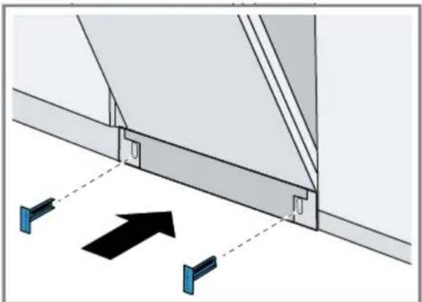
- Slide the supplied brackets into the slots of the toe panel you just attached.
natural_image
Diagram of a structural connection with two blue components and an upward-pointing arrow (no text or symbols)-
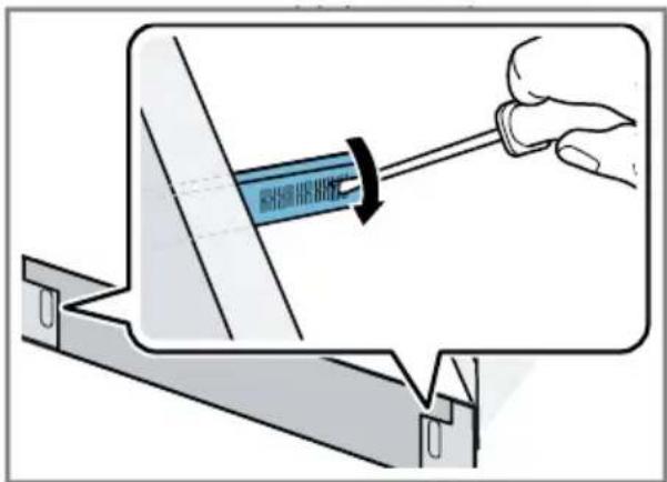
To ensure that the outer toe panel is flush with the cabinetry base, determine the correct position for the brackets.
-
Mark the correct position, then slide the brackets out and bend out the metal tab at the correct position.
natural_image
Illustration of a hand using a screwdriver to adjust a component, showing a blue tool inside a metal frame (no text or symbols)Bending a tab ensures that the toe panel cannot slide in further.
-
Re-insert the brackets.
-
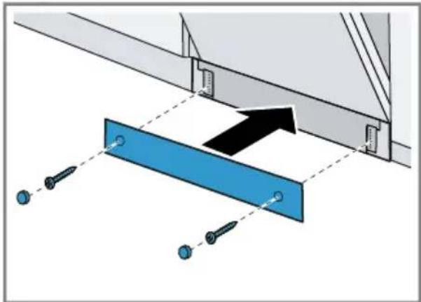
Secure the outer toe panel with the crosshead screws provided.
- The outer toe panel should completely cover the rubber apron.
- To cover the screw heads, use the black plastic caps.
natural_image
Diagram showing a blue beam supported by screws, with an arrow indicating upward motion (no text or symbols present)Follow these instructions to connect the dishwasher.
5.1 Installing the Water Inlet Connection
The hot water heater should be set to deliver approximately 120 °F (49 °C) [max. 140 °F/ (60 °C)] water to the dishwasher. Water that is too hot can cause some detergents to lose effectiveness. Lower water temperatures will increase run times. The hot water supply pressure must be between 7.25 - 145 psi (0.5 - 10 bar).

WARNING
Scalding Hazard
- Do not perform any work on a pressured hot water line. Serious injury could result. Only qualified plumbers should perform plumbing work. Do not attempt any work on the dishwasher hot water supply plumbing until you are certain the hot water supply is shut off.
NOTICE:
Soldering plumbing lines
- Temperatures required for soldering and sweating will damage the dishwasher. If plumbing lines are to be soldered or sweated, keep the heat source at least 6 inches (152.4 mm) away from the dishwasher.
Plumbing codes
- Check local plumbing codes for approved plumbing procedures and accessories. All plumbing should be done in accordance with national and local codes.
Note
Important notes for water connection:
■ If using a solder joint instead of a compression fitting, be sure to complete all solder connections before connecting the water supply line to the dishwasher.
■ Use an approved dishwasher water supply line with the correct fittings for this connection.
■ If using copper tubing or other material not depicted in this manual for water supply, defer to a licensed plumber for proper installation.
■ Always use appropriate seals when making plumbing connections.
-
Flush the incoming water line for approximately 1 minute to clear any foreign material.
-
Connect the dishwasher water supply line to the water shut off valve, using the adaptor if included with your model. Turn by hand and do not over tighten.
-
Install a shut off valve if one isn't already in the supply line.
- Make sure there are no sharp bends or kinks in the water line that might restrict water flow.
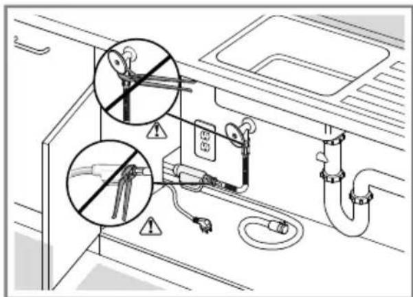
- After all connections are made, turn on the hot water and check for leaks.
5.2 Installing the Drain Connection
The drain hose must be installed with either a high loop or an air gap.
NOTICE:
Proper drain hose installation
- The dishwasher drain hose must be installed with a portion of it at least 33" (84 cm) off the floor; otherwise the dishwasher may not drain properly.
Remove garbage disposal plug
If the dishwasher drain hose will be connected to a garbage disposal connection, first remove the plug from the disposal connection.
Note
Important notes for drain connection:
If local ordinance require an air gap, install it according to the manufacturer's instructions.
■ The drain hose length can be extended if necessary. Use kit #SGZ1010UC. The maximum length of the drain hose, including the hose leading to the air gap, is 150" (380 cm).
- You may attach the hose clip to the inside of the adjacent cabinet to hang the drain hose (screws are not supplied) in place of using a nonmetallic tie as pictured in the next illustrations. Do not exceed 43" in drain hose height.
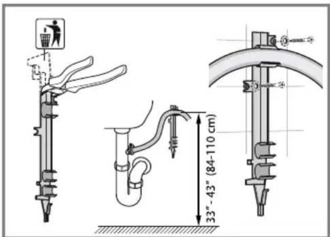
- Place hose clamp around end of drain hose BEFORE connecting to the plumbing.
en-us Customer Service
- If you have a garbage disposal, connect the drain hose to the garbage disposal with either a high loop or an air gap.
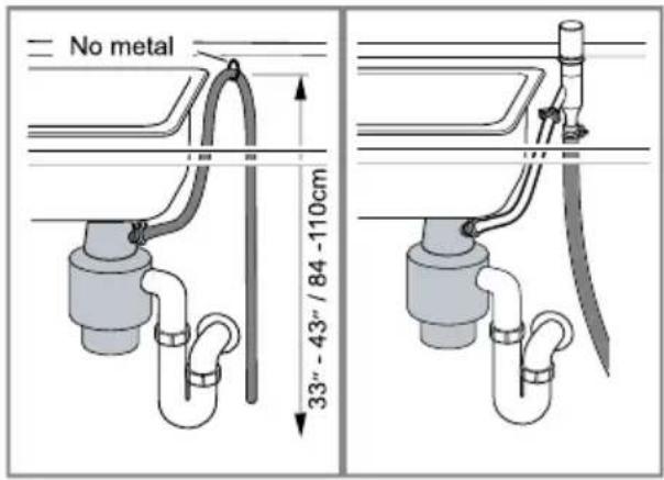
- If you do not have a garbage disposal, connect the drain hose to the drain connection with either a high loop or an air gap.
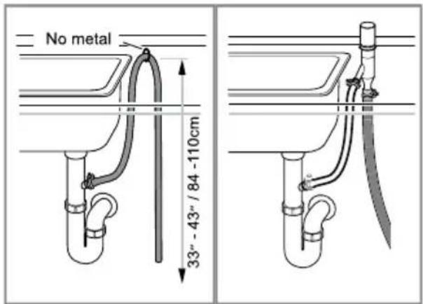
-
Insert the included drain hose adaptor before connecting to the plumbing.
-
Tighten the hose clamp around the house plumbing.
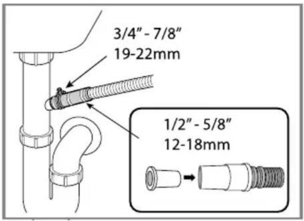
5.3 Electrical Connection and Test Cycle
- For wall outlet connections, plug the dishwasher into the outlet.
- Turn on power supply.
- Make sure the water supply is on.
- Turn the dishwasher on and run a test cycle for 15 minutes.
- Check to make sure the cycle operates and there are no leaks while it is running.
- Stop the cycle and turn off the dishwasher.
- Your installation is complete.
6 Customer Service
With any warranty repair, we will make sure your appliance is repaired by an authorized service provider using
genuine replacement parts. We use only genuine replacement parts for all repairs.
Detailed information on the warranty period and terms of warranty can be found in the Statement of Limited Product Warranty, from your retailer, or on our website.
If you contact Customer Service, you will need the model number (E-Nr.) and the production number (FD) of your appliance.
USA:
1-877-442-4436
www.gaggenau.com
www.gaggenau.com/us/appliances/eshop
CA:
1-877-442-4436
www.gaggenau.com
www.gaggenau.ca
6.1 Model number (E-Nr.) and production number (FD)
You can find the model number (E-Nr.) and the production number (FD) on the appliance's rating plate.
The rating plate is located inside the appliance door.
Making a note of your appliance's details and the Customer Service telephone number will enable you to find them again quickly.
6.2 AquaStop® Plus Pledge
In addition to the standard warranty provided by BSH, BSH will also compensate customers for damage caused by a specific fault in the AquaStop system giving rise to a valid warranty claim. Compensation will be provided under the following conditions:
■ If water damage is caused by a defect in materials or workmanship in the AquaStop system, BSH will compensate customers reasonable and verifiable damages.
■ A condition of all warranty claims is the appliance with AquaStop must have been installed and connected correctly in accordance with all instructions; this also includes a properly installed AquaStop extension (genuine accessories). The warranty does not cover defective feed lines or fittings leading to the AquaStop connection at the tap.
fr-ca
Table des matières
1 IMPORTANTES CONSIGNES DE SÉCURITÉ.... 27
natural_image
3D diagram of a white appliance with a black arrow pointing to the lid area (no text or symbols)natural_image
Diagram showing two electrical insulator components with arrows indicating rotation or movement (no text or symbols)natural_image
Diagram of a blue structural beam supported by a tool, with an inset showing a tree (no text or symbols present)natural_image
Technical diagram of a door assembly with a circular component and mounting base (no text or symbols)natural_image
Diagram of a device with blue plastic casing and directional arrows indicating flow or movement (no text or symbols)natural_image
Technical line drawing showing two views of a mechanical component with labeled dimension A (no text or symbols present)natural_image
Diagram showing a hammer striking a flat surface with a screwdriver, no text or symbols presentnatural_image
Technical diagram showing a blue tool inserted into a flat plate with a small inset detail labeled ∅2 and ~12 (no text or symbols on the diagram itself)natural_image
Diagram of a refrigerator interior showing door, drawer, and storage unit with directional arrows (no text or labels)natural_image
Architectural detail drawing showing a door frame with a ruler and directional arrow (no text or symbols)natural_image
Diagram of a door frame with directional arrows indicating movement, showing structural components and a magnified inset (no text or symbols)natural_image
Technical line drawing of a cabinet or enclosure structure with mounting brackets and structural details (no text or symbols)natural_image
Technical line drawing of a door frame assembly with an arrow indicating direction (no text or symbols)natural_image
Diagram of a piping system with a wheel and directional arrow, no text or symbols presentnatural_image
Technical diagram showing a structural assembly with mounting brackets and a close-up of a bracket with screws (no text or symbols present)natural_image
Technical line drawing of a structural frame with two inset views showing internal components (no text or symbols)natural_image
Diagram showing two mechanical assembly steps with arrows indicating motion direction (no text or symbols)4.15 Fixer la plinthe externe
AVIS :
natural_image
Diagram of a structural connection detail showing two blue clamps and a black arrow indicating direction (no text or symbols)natural_image
Illustration of a hand using a tool to adjust a blue component on a metal bracket (no text or symbols)natural_image
Diagram showing a blue beam supported by screws, with an arrow indicating direction (no text or symbols present)www.gaggenau.com/us/appliances/eshop
CA:
1-877-442-4436
www.gaggenau.com
www.gaggenau.ca
1901 Main Street, Suite 600
Irvine, CA 92614
USA
www.gaggenau.com
1-877-442-4436
© 2024 BSH Home Appliances Corporation
- Before you begin.... 7
- Installation Preparation ...... 10
- Installation Procedure ...... 11
- Dishwasher Connection ..... 22
- Customer Service 24
- Safety definitions
- WARNING
- CAUTION
- NOTICE:
- General information
- Safe Installation
- Electrical safety
- Avoid Electrical Shock
- Avoid Fire Hazard
- Wall outlet connections
- Permanent wire connections (in addition to the warnings above)
- State of California Proposition 65 Warnings
- Before you begin
- Inspect the Dishwasher
- Parts Included
- en-us Before you begin
- Tools and Parts Needed
- Center Punch
- Parts
- Pre-install Checklist
- Electrical Requirements
- Electrical Supply
- en-us Installation Preparation
- Cabinet Requirements
- Installation Preparation
- ⚠️ WARNING - Risk of
- Installation Procedure
- Attach Steam Fender
- Pre-level the Dishwasher
- en-us Installation Procedure
- Attach Power Cord
- Notes
- Mounting Brackets Vario Hinge
- Avoid tip over hazard
- Top and Side Mount
- Side Mount Force Distributor
- Attaching the Apron
- Prepare the Panel
- Attach Panel Mounting Brackets
- Attach the Panel and Deco Strips
- Install Dishwasher in Cabinet Space
- Level the Dishwasher
- Secure Top and Side Mount
- Opening the door
- Adjust door opening
- Attach the 2-part Toe Panel
- Attach the Outer Toe Panel
- Installing the Water Inlet Connection
- Scalding Hazard
- Soldering plumbing lines
- Plumbing codes
- Note
- Installing the Drain Connection
- en-us Customer Service
- Electrical Connection and Test Cycle
- Customer Service
- Model number (E-Nr.) and production number (FD)
- AquaStop® Plus Pledge
- fr-ca
- Table des matières
- IMPORTANTES CONSIGNES DE SÉCURITÉ.... 27
- Fixer la plinthe externe
- AVIS :
Brand : GAGGENAU
Model : DF481701F
Category : Washing machine