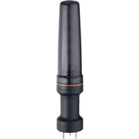
DV1501 - Signal lamp IFM - Free user manual and instructions
Find the device manual for free DV1501 IFM in PDF.


User questions about DV1501 IFM
0 question about this device. Answer the ones you know or ask your own.
Ask a new question about this device
Download the instructions for your Signal lamp in PDF format for free! Find your manual DV1501 - IFM and take your electronic device back in hand. On this page are published all the documents necessary for the use of your device. DV1501 by IFM.
USER MANUAL DV1501 IFM
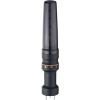
Operating instructions 5-segment light tower
DV15x1
Contents
1 Preliminary note 3
1.1 Symbols used 3
2 Safety instructions.... 4
3 Intended use.... 5
4 Function 6
4.1 IO-Link 6
5 Installation.... 7
6 Electrical connection.... 8
6.1 Pin assignment 8
7 Operating and display elements 9
8 Operation 10
8.1 Demo mode 10
9 Parameter setting 11
9.1 Parameter setting via IO-Link 11
9.2 Parameter setting via the parameter setting button.... 11
9.2.1 Parameter structure 11
10 Maintenance, repair and disposal 13
1 Preliminary note
You will find instructions, technical data, approvals and further information using the QR code on the unit / packaging or at documentation.ifm.com.
1.1 Symbols used
√ Requirement
Instructions
Reaction, result
[...] Designation of keys, buttons or indications
→ Cross-reference

Important note
Non-compliance may result in malfunction or interference.

Information
Supplementary note
2 Safety instructions
- The unit described is a subcomponent for integration into a system.
- The system architect is responsible for the safety of the system.
-
The system architect undertakes to perform a risk assessment and to create documentation in accordance with legal and normative requirements to be provided to the operator and user of the system. This documentation must contain all necessary information and safety instructions for the operator, the user and, if applicable, for any service personnel authorised by the architect of the system.
-
Read this document before setting up the product and keep it during the entire service life.
- The product must be suitable for the corresponding applications and environmental conditions without any restrictions.
- Only use the product for its intended purpose (→ Intended use).
- If the operating instructions or the technical data are not adhered to, personal injury and/or damage to property may occur.
- The manufacturer assumes no liability or warranty for any consequences caused by tampering with the product or incorrect use by the operator.
• Installation, electrical connection, set-up, programming, configuration, operation and maintenance of the product must be carried out by personnel qualified and authorised for the respective activity. - Protect units and cables against damage.
- Replace damaged units, otherwise the technical data and safety will be impaired.
- Observe applicable documents.
3 Intended use
The unit is used for the visual display of machine conditions. The versions DV1511 and DV1531 additionally have a buzzer for acoustic signalling.
The LED segments and the audible warning device can be switched on and off individually.

The unit is not suited for environments with particular requirements on mechanical stability (e.g. shock/vibration).
The unit is intended for indoor use only.
▶ Observe the operating conditions ( → Technical data at www.ifm.com).

The unit is not approved for safety-related tasks in the field of operator protection.
4 Function
The individual LED segments and the buzzer can be switched separately via digital inputs.
Parameters are set via a parameter setting button or via the IO-Link interface.
The status of the 5 LED segments and the buzzer can be read via IO-Link. This data can be forwarded to the machine data analysis (MDA) for evaluation.
4.1 IO-Link
This unit has an IO-Link communication interface which enables direct access to process and diagnostic data. In addition it is possible to set the parameters of the unit while it is in operation. Operation of the unit via the IO-Link interface requires an IO-Link master.
With a PC, suitable IO-Link software and an IO-Link adapter cable, communication is possible while the system is not in operation.
The IODDs necessary for the configuration of the unit, detailed information about process data structure, diagnostic information, parameter addresses and the necessary information about the required IO-Link hardware and software can be found at www.ifm.com.
5 Installation

▶ Disconnect the power of the machine before installation.

▶ For installation choose a flat mounting surface.
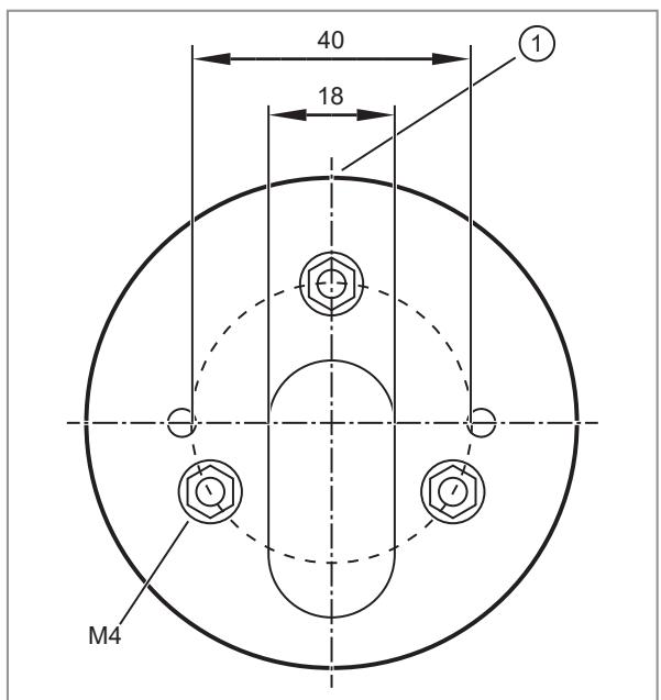
Fig. 1: Fixture (view from bottom)
1: Front side
▶ Attach the fixture for the device to the mounting surface using the supplied M4 nuts. Tightening torque 1.8 Nm.
▶ Only with the models DV1501 and DV1511:
For mounting on a horizontal surface attach the base to the fixture (overlapping marks on base and fixture) and turn clockwise by approx. 10° to fix it. For mounting on a vertical surface loosen the screw in the base, turn the upper part of the base by 180° and tighten the screw again. Attach the base to the fixture (overlapping marks on base and fixture) and turn clockwise by approx. 10° to fix it.
▶ Insert the cable through the fixture and, if necessary, the base and connect the socket with the M12 connector in the signal lamp. Tightening torque max. 0.4 Nm. (Observe the maximum tightening torque of the connection cables.)
▶ Attach the signal lamp to the fixture or the base (overlapping marks) and turn clockwise by approx. 10° to fix it.

Integrated seals at the bottom of the fixture and in the base as well as O-rings at the fixture and base prevent ingress of moisture.

Information about available accessories at www.ifm.com
6 Electrical connection
The unit must be connected by a qualified electrician. Observe the national and international regulations for the installation of electrical equipment. Voltage supply according to SELV, PELV.
The IO-Link port must be connected according to the IO-Link specification.
▶ Disconnect power.
▶ Connect the cable with the M12 connector of the unit. Tightening torque max. 0.4 Nm.
Observe the maximum tightening torque of the connection cable.
6.1 Pin assignment
M12 plug, 8-pole (8 x 0.25 mm 4 / AWG 24)

1: LED segment 5
2: buzzer (DV1511 and DV1531)
3: LED segment 3
4: LED segment 2
5: GND
6: LED segment 1
7: LED segment 4
8: IO-Link
Polarity of the inputs ▶ Connect pin 5 to GND to trigger the inputs with a PNP transistor.
IO-Link output and parameter setting: ▶ Connect pin 5 to GND. ▶ Connect pin 8 to IO-Link.
! Connection cable E12572 can only be used for parameter setting. The Y communication cable E12798 can be used for the IO-Link connection.
7 Operating and display elements

1: Parameter setting button
2: LED segment 1 with 4 RGB LEDs
3: LED segment 2 with 4 RGB LEDs
4: LED segment 3 with 4 RGB LEDs
5: LED segment 4 with 4 RGB LEDs
6: LED segment 5 with 4 RGB LEDs
7: Buzzer (only DV1511 and DV1531)
8: Feedback LED
8 Operation
The device is connected to the digital outputs of the controller via an 8-pole connection cable (see accessories at www.ifm.com). The HTL inputs of the signal lamp are triggered with 24 V DC. According to the set parameters the LED segments are on and the buzzer sounds (if available).
The signal inputs can be triggered in PNP technology ( → Electrical connection > Pin configuration > Standard device).
The following properties can be set for every LED segment:
• Colour (red, green, orange, blue, purple, turquoise, white, yellow, off)
• Frequency (permanently on, flashing slow/medium/fast, blinking slow/medium/fast)
• Brightness (100 %, 75 %, 50 %, 25 %)
Parameter setting via the IO-Link interface (pin 8 of the M12 connector) is possible. Alternatively, the device can also be set using the parameter setting button.
After parameter setting the device changes to the Run mode.
8.1 Demo mode
In demo mode, the device demonstrates the different
- Colours
• Visual indications of analogue values (styles) - Buzzer sounds (buzzer styles, provided the device features a buzzer)
Set the parameter [Demo mode] in the IO-Link parameter setting tool. For SIO and IO-Link mode, the demo is available in 3 different speeds, respectively.
9 Parameter setting
9.1 Parameter setting via IO-Link
Parameter setting via the IO-Link interface (pin 8 of the M12 connector) is possible.

IO Device Description (IODD) with all parameters and process data of the unit can be found at documentation.ifm.com.
9.2 Parameter setting via the parameter setting button
▶ Turn the transparent protective cover anticlockwise by approx. 10 ° and remove it.
▶ Briefly press the parameter setting button at the head of the device (< 5 s).
▷ The feedback LED is lit in green.
The device is in parameter setting mode.
▶ Briefly press the parameter setting button (< 5 s) to go to the next parameter.
▶ Press the parameter setting button for a longer time (> 5 s) to set the selected parameter.
▷ The feedback LED flashes green.
▷ The device indicates the current settings of the LED segment to be configured.
▶ Briefly press the parameter setting button (< 5 s) to change the value for the selected parameter. Repeat this step until the requested setting is selected.
The device indicates the current settings of the LED segment to be configured.
▶ Press the parameter setting button for a longer time (> 5 s) to save the selected value for this parameter.
▷ The feedback LED flashes green.
The device saves the value and goes to the next parameter.
▷ After configuration of all LED segments the device displays the current settings of all LED segments.
▶ Briefly press the parameter setting button (< 5 s) to finish the parameter setting mode.
▷ The feedback LED goes out. The device is in the Run mode.

If the parameter setting button is not pressed for longer than 30 seconds, the device saves the last changes and goes to the Run mode.
9.2.1 Parameter structure
| LED seg. | Parameter | Value | ||||||||
| 1 | Colour | Red | Green | Orange | Blue | Violet | Tur-quoise | White | Yellow | Off |
| Frequency | On | Flashing slow | Flashing medium | Flashing fast | Blinking slow | Blinking medium | Blinking fast | |||
| Brightness | 100% | 75% | 50% | 25% | ||||||
| 2 | Colour | Red | Green | Orange | Blue | Violet | Tur-quoise | White | Yellow | Off |
| Frequency | On | Flashing slow | Flashing medium | Flashing fast | Blinking slow | Blinking medium | Blinking fast | |||
| Brightness | 100% | 75% | 50% | 25% | ||||||
| 3 | Colour | Red | Green | Orange | Blue | Violet | Tur-quoise | White | Yellow | Off |
| 3 | Frequency | On | Flashing slow | Flashing medium | Flashing fast | Blinking slow | Blinking medium | Blinking fast | ||
| Brightness | 100% | 75% | 50% | 25% | ||||||
| 4 | Colour | Red | Green | Orange | Blue | Violet | Tur-quoise | White | Yellow | Off |
| Frequency | On | Flashing slow | Flashing medium | Flashing fast | Blinking slow | Blinking medium | Blinking fast | |||
| Brightness | 100% | 75% | 50% | 25% | ||||||
| 5 | Colour | Red | Green | Orange | Blue | Violet | Tur-quoise | White | Yellow | Off |
| Frequency | On | Flashing slow | Flashing medium | Flashing fast | Blinking slow | Blinking medium | Blinking fast | |||
| Brightness | 100% | 75% | 50% | 25% | ||||||
10 Maintenance, repair and disposal
Cleaning the unit:
▶ Disconnect the unit from the voltage supply.
▶ Clean the unit from dirt using a soft, chemically untreated and dry micro-fibre cloth.
The operation of the unit is maintenance-free.
Only the manufacturer is allowed to repair the unit.
▶ After use dispose of the device in an environmentally friendly way in accordance with the applicable national regulations.
- 1 PRELIMINARY NOTE
- 1.1 SYMBOLS USED
- 2 SAFETY INSTRUCTIONS
- 3 INTENDED USE
- 4 FUNCTION
- 4.1 IO-LINK
- 5 INSTALLATION
- 6 ELECTRICAL CONNECTION
- 6.1 PIN ASSIGNMENT
- 7 OPERATING AND DISPLAY ELEMENTS
- 8 OPERATION
- 8.1 DEMO MODE
- 9 PARAMETER SETTING
- 9.1 PARAMETER SETTING VIA IO-LINK
- 9.2 PARAMETER SETTING VIA THE PARAMETER SETTING BUTTON
- 9.2.1 PARAMETER STRUCTURE
- 10 MAINTENANCE, REPAIR AND DISPOSAL
Brand : IFM
Model : DV1501
Category : Signal lamp