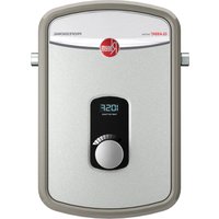
RTEX-08 - Boiler Rheem - Free user manual and instructions
Find the device manual for free RTEX-08 Rheem in PDF.


| Product type | Electric tankless water heater (instantaneous) |
| Brand | Rheem |
| Model | RTEX-08 |
| Power rating | 3.5 kW (120 V) or 5.5 kW (220 V) |
| Power supply voltage | 120 V (3.5 kW model) or 220 V (5.5 kW model) |
| Maximum current | 29 A (3.5 kW) / 25 A (5.5 kW) |
| Required circuit breaker | 1 x 30 A (3.5 kW) / 1 x 25 A double-pole (5.5 kW) |
| Required wire gauge | 10 AWG |
| Activation flow rate | 0.3 GPM (1.1 LPM) |
| Maximum water pressure | 150 PSI (1035 kPa) |
| Connections | Inlet and outlet 1/2" NPT |
| Installation | Indoor only, vertical with bottom connections |
| Recommended clearances | 304.8 mm (12 in) top/bottom, 152.4 mm (6 in) front/sides |
| Display | Digital outlet temperature |
| Control | Power on/off button |
| Thermal protection | Electronic thermostat + electromechanical auto-reset switch |
| Safety | Requires installation by qualified electrician and plumber; turn off power before servicing |
| Maintenance | Annual inspection of connections; descaling if hard water; purge air before powering on |
| Warranty | Contact customer service at 1 800 374-8806 |
Frequently Asked Questions - RTEX-08 Rheem
User questions about RTEX-08 Rheem
0 question about this device. Answer the ones you know or ask your own.
Ask a new question about this device
Download the instructions for your Boiler in PDF format for free! Find your manual RTEX-08 - Rheem and take your electronic device back in hand. On this page are published all the documents necessary for the use of your device. RTEX-08 by Rheem.
USER MANUAL RTEX-08 Rheem
Electric Tankless Water heaters
INSTALLATION INSTRUCTIONS & HOME OWNERS MANUAL
IMPORTANT SAFETY INFORMATION
When installing or using any high voltage electrical appliance, basic safety precautions should always be followed. Under no circumstance should you aempt to clean, install, inspect, repair, disassemble or otherwise service this water heater, without rst shung o all power to the unit directly at the circuit breaker box. SERIOUS BODILY INJURY OR DEATH COULD OCCUR IF YOU IGNORE THIS WARNING.
THIS PRODUCT SHOULD BE INSTALLED BY A QUALIFIED ELECTRICIAN AND A QUALIFIED PLUMBER IN ACCORDANCE WITH ALL NATIONAL, STATE, PROVINCIAL AND LOCAL ELECTRICAL & PLUMBING CODES.
PLEASE READ THESE INSTRUCTIONS THOROUGHLY AND COMPLETELY PRIOR TO INSTALLATION & USE. FAILURE TO DO SO COULD CAUSE PROPERTY DAMAGE, SERIOUS INJURY, OR DEATH.
This manual should be given to the homeowner aer installaon and should be retained for future reference.
Proposition 65 Warning: This product contains chemicals known to the State of California to cause cancer, birth defects or other reproductive harm

Tested and cered by the Water Quality Associaon against NSF/ANSI 372 for lead free compliance.

Recognize this symbol as an indicaon of Important Safety Informaon!
DO NOT destroy this manual. Please read carefully and keep it in a safe place for future reference
IMPORTANT SAFETY INFORMATION. READ ALL INSTRUCTIONS BEFORE USING


DANGER! WATER TEMPERATURE SAFETY SETTING
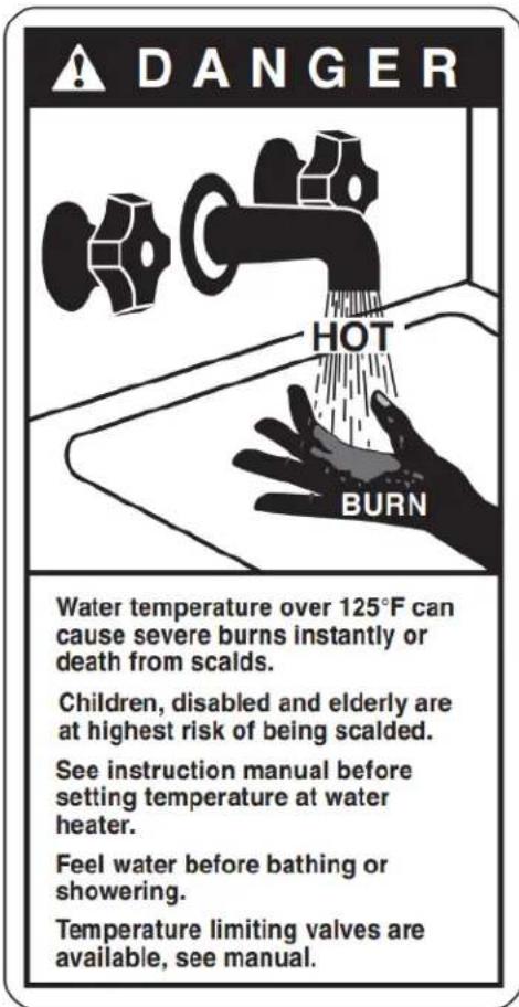
Safety and energy conservaon are factors to be considered when selecng the water temperature seng of water heater's thermostat. Water temperatures above the 125°F (52°C) can cause severe burns or death from scalding. Be sure to read and follow the warnings outlined on the label pictured below. This label is also located on the water heater near the thermostat access panel.
Noce: Mixing valves are recommended for reducing point of use water temperature by mixing hot and cold water in branch water lines. It is recommended that a mixing valve complying with the Standard for Temperature Actuated Mixing Valves for Hot Water Distribuon Systems, ASSE 1017 be installed.
Time/Temperature Relationship in Scalds
| Water Temperature | Time to Produce a Serious Burn |
| 120°F (49°C) | More than 5 minutes |
| 125°F (52°C) | 1 1/2 to 2 minutes |
| 130°F (54°C) | About 30 seconds |
| 135°F (57°C) | About 10 seconds |
| 140°F (60°C) | Less than 5 seconds |
| 145°F (63°C) | Less than 3 seconds |
| 150°F (66°C) | About 1 1/2 seconds |
| 155°F (68°C) | About 1 second |
Table courtesy of Shriners Burn Institute
The chart shown above may be used as a guide in determining the proper water temperature for your home.

DANGER
Once the unit is installed and checked for
water leaks turn the breaker on and push the power buon to acvate heater. Heater can be deactivated by pushing the power buon one more me. When the heater is powered on the electronic control will automatically power the element when it senses water ow.
The temperature of the hot water delivered by the heater depends on the waage of the heang element, temperature of the incoming cold water and the water ow rate through the water heater. Reducing the ow rate increase the outlet temperature and increasing the ow rate reduces the outlet temperature.
It is important to keep in mind that all tankless water heaters are subject to a maximum ow rate. The heater will not be capable of heang water to desired temperature if the ow rate exceeds heaters capability. In order for the heater to operate properly, it must be carefully matched to its applicaon and aerators should be used to limit water ow. See the Table I to determine the maximum ow rates and temperature rise for each model.

CAUTION
Outlet water temperature may be higher
when using the tankless heater at low ow rates or when used with high inlet water temperature.
ABOUT YOUR TANKLESS WATER HEATER
Congratulaons on the purchase of your Electric Tankless Water Heater!
To get the best performance and energy savings from your electric tankless water heater, it is important that it be installed in accordance with our instrucons and the electrical and plumbing codes applicable to your area, and that you read this manual thoroughly for important operang instrucons and ps.
If you have quesons at any me, please contact us directly at:
Manufacturer's Naonal Service Department
400 Captain Neville Dr. Waterbury, CT 06705 Phone: 1-(800)-374-8806.
CONTENTS
- BEFORE INSTALLATION
- SELECTING A LOCATION TO INSTALL
- MOUNTING YOUR WATER HEATER
- PLUMBING INSTALLATION
- ELECTRICAL INSTALLATION
- SIZING GUIDE
- GENERAL OPERATING INSTRUCTIONS
- MAINTENANCE
- TROUBLE SHOOTING GUIDE
- USER INTERFACE
1- BEFORE INSTALLATION
PLEASE READ THESE INSTRUCTIONS THOROUGHLY AND COMPLETELY PRIOR TO INSTALLATION & USE. FAILURE TO FOLLOW INSTRUCTIONS COULD CAUSE PROPERTY DAMAGE, SERIOUS PERSONAL INJURY, OR DEATH.
By installing this product, you acknowledge the terms of the manufacturer's warranty. Once the heater is installed, do not return product to the place of purchase. If you have any quesons regarding the warranty or product return policies, please contact Manufacturer's naonal service department at 1-(800) 374-8806.
Inspect all components. The contents of your box should include one of the following units:
- 3.5kW
- 5.5kW
2- SELECTING A LOCATION TO INSTALL
This product is designed to be installed indoors only.

DO NOT install this product in a locaon where it may be subjected to freezing temperatures. If the water inside your tankless water heater freezes, it can cause severe and permanent damage that is not covered by your warranty.

DO NOT locate the water heater in a locaon that is dicult to access.
Make sure that the water heater and hot water outlet pipe are out of reach of children so they are unable to tamper with the temperature controls or injure themselves by touching the hot water outlet pipe. The outlet water pipe can get very hot.
This product does NOT require venng.
Avoid installing your tankless water heater in a locaon prone to excessive humidity, moisture, or dust, or in an area where it may be splashed with water or other liquids. DO NOT install under water pipes or air condining lines that might leak or condense moisture that could then drip onto the heater. DO NOT install above electrical boxes or juncons.

CAUTION The water heater should not be located in an area where leakage will result in damage to the adjacent to it or to lower oors of the structure. Where such areas cannot be avoided, it is recommended to suitable catch pan, adequately drained, be installed under the water heater. Make sure to follow all code rements for such installaons as required for your area. We recommend that you install a drip pan (selected to a safe drain) below the water heater to avoid property damage in the unlikely event of a leak. Havely, you can install an acve water leak detector and shuto valve designed to turn o your water by in the event that a leak is ever detected.
3- MOUNTING YOUR WATER HEATER
Your tankless water heater should be secured to the mounng surface with 4 screws (minimum 1" (25.4mm) long) follow the installaon template for heaters. Make sure that the mounng surface is solid and secure, and ensure that the unit is level prior to securing the screws. For ease of installaon and servicing, we recommend that this product be installed in an upright posion with the inlet and outlet water connecons at the boom of the unit.
Recommended Clearances:
6" (304.8mm) above and below the heater
6" (152.4mm) in front of and to the sides of the heater

Flammable materials should be kept at least 24" (609.6mm) away from your water heater and the hot water outlet pipe.
4- PLUMBING INSTALLATION
Please follow all plumbing instrucons carefully. We recommend that this product be installed by a licensed and qualified plumber in accordance with all applicable naonal, state, provincial, and local plumbing codes.
Installaon Instrucons
This water heater is supplied with 1/2 " NPT ngs, DO NOT weld or use paste.
STEP 1: Thoroughly ush cold supply line of debris and connect the HOT WATER line to the water heater OUTLET located on the le side of the heater when facing unit. Connect the COLD WATER line to the water heater marked COLD WATER INLET on the right side when facing unit.
STEP 2: Aer ghtening both ngs at the water heater, open several hot water faucets and allow water to run though the water heater for at least 2 to 3 minutes. This process purges all the air from the water lines and MUST be performed prior to turning on the power at the unit. FAILURE TO FOLLOW THIS STEP CAN CAUSE PERMANENT DAMAGE TO THE HEATING ELEMENTS. If any maintenance is performed on the water heater or the home's plumbing system that may introduce air into the plumbing pipes, it is important to turn the power o to the water heater and purge the air out of the lines before allowing the unit to power up.
STEP 3: Carefully inspect all connecons, unions, and the pressure relief valve (if installed) for leaks.
IMPORTANT NOTES:
- Do not solder any pipes with the unit connected to pipes – heat from soldering may damage the ow sensor. Doing so will void the warranty.
-
This automac tankless water heater is equipped with both computer-controlled and electro-mechanical auto reseng thermostat switches for high-limited temperature protecon. Since this product does not use a storage tank, the use of a temperature pressure relief valve (T&P) is not required for most installaons. UL Standard 499 does NOT require that a pressure relief valve be used. However, a T&P valve may be required to meet installaon codes in your area. If one is required, install the pressure relief valve in accordance with local codes and ensure that it operates correctly and that air is purged from the valve prior to installing the water heater. When connecng to Flex or High Temperature CPVC pipe, we recommend that a T&P valve be used for added safety. Please note: Installaons in the Commonwealth of Massachusetts and State of Kentucky require a pressure relief valve. Please check your local installaon codes for any special requirements.
-
The maximum operang water pressure is 150 PSI (1035 kPa). If the water pressure is higher, a pressure reducing valve must be installed on the main incoming water supply line prior to installing the electric tankless water heater.
-
Flexible water heater hoses are recommended to be used with your water heater as part of the installaon. When connecng the inlet water pipe to the unit, make sure to use a wrench to hold the unit's conncon, and another wrench to ghten, so that the ow sensor on the unit will not be loosened or damaged. Serious internal damage to the water heater can occur if the inlet or outlet conncons are over ghtened or if solder conncons were made.
-
We recommend that a manual shut-o valve (ball valve) is installed on the inlet and outlet of the water heater so that there is a convenient shut-o point available in the event that future maintenance or servicing is required. It is extremely important to ush the lines to eliminate all plumbing paste or residue in the lines caused by any welding or soldering before connecng pipes to the water heater.
We recommend that all the water pipes or hoses within 3' (1m) of the inlet and outlet connecons be rated for high temperature applicaons with a 150° F ( 66° C) minimum.

WARNING CHECK FOR LEAKS BEFORE PROCEEDING TO ELECTRICAL INSTALLATION
5- ELECTRICAL INSTALLATION

WARNING Manufacturer recommends that this product be installed by a licensed and qualified electrician in accordance with all applicable naonal, state, provincial, and local electrical codes. As with all electrical appliances, under no circumstances should you aempt to install, repair or disassemble this water heater without rst shung o all power to the unit directly at the fuse or breaker box. Make sure to shut o all breakers. SERIOUS BODILY INJURY OR DEATH COULD OCCUR IF YOU IGNORE THIS WARNING.
All wiring (wire gauge) and circuit protecon (breakers) must comply with the U.S. Naonal Electrical Code (NEC) in the USA, or the Canadian Electrical Code (CEC) in Canada. Failure to do so could result in property damage and/or personal injury, and void your warranty. Note: The Canadian Electrical Code generally requires that all supply wires and corresponding circuit protecon used for domesc hot water heang and hydronic heang applicaons be sized to a minimum of 125% of the maximum current rang of the heater (see heater speciaons below for details).
Before installing this product, ensure that the home has sufficient electrical power available to handle the maximum amperage load of the applicable heater.
IMPORTANT NOTES:
3.5 and 6.0 kW heaters require 1 set of wire and ground (see wiring diagram)
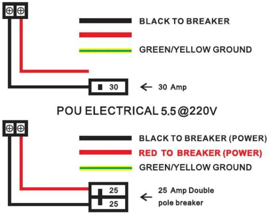
Please see electrical speciaons by heater input and wiring diagram on the next page for additional electrical informaon.
Each set of wires must be connected to its own individual double pole breaker.
Installaon Instrucons
STEP 1: Take each wire pair and connect them to one breaker (see wiring diagram). Make sure that each breaker is connected with one black wire and one red wire
STEP 2: Using a suitable wire gauge that meets all applicable electrical codes for the size of the breakers used, run the correct sets of wire from the home's main breaker panel to the tankless water heater.
STEP 3: A separate ground conductor for each incoming circuit is required.
STEP 4: DOUBLE CHECK the electrical connecons to make sure they are correct and that all wire connections are ght and secure. Also conrm that the correct breaker size and wire gauge has been used and conrm that the unit has been connected to a ground in accordance with applicable codes.
STEP 5: Conrm that all the air has been purged from the water lines prior to turning on power to the unit. Refer to STEP 2 in the plumbing installaon secon.

CAUTION Ensure that you have made the correct conncons. You must follow the wire conncon as to ensure proper operaon of the unit. If you mix up one set of wires with another, the unit will not quite correctly even though it turns on and otherwise appears to funcon properly.
The water heater is now installed and ready to use! Follow the General Operang Instrucons to complete the setup. We highly recommend that this is done with the homeowner present.
Electrical Specicaons by Heater Input
| HEATER INPUT | 3.5kW | 5.5kW |
| ELEMENTS | 1 | 1 |
| VOLTAGE | 120 V | 220 V |
| MAX kW | 3.5kW | 5.5 kW |
| MAX AMPERAGE DRAW | 29AMPS | 25 AMPS |
| REQUIRED BREAKERS | 1 x 30 AMP | 1 X 30 AMP |
| REQUIRED WIRE GAUGE | 1 x 10 AWG | 1 x 10 AWG |
POU ELECTRICAL 3.5@120V
6- SIZING GUIDE
The chart below indicates maximum temperature rise for a given ow rate
| GPM | GPM to Temp Rise in °F | |||||||||||||||
| 0.3 | 0.4 | 0.5 | 0.6 | 0.7 | 0.8 | 0.9 | 1 | 1.1 | 1.2 | 1.3 | 1.4 | 1.5 | 1.6 | 1.7 | ||
| POU KW | 3 | 68.3 | 51.2 | 41.0 | 34.2 | 29.3 | 25.6 | 22.8 | 20.5 | 18.6 | 17.1 | 15.8 | 14.6 | 13.7 | 12.8 | 12.1 |
| 5.5 | 125.2 | 93.9 | 75.1 | 62.6 | 53.7 | 47.0 | 41.7 | 37.6 | 34.2 | 31.3 | 28.9 | 26.8 | 25.0 | 23.5 | 22.1 | |
| LPM | LPM to Temp Rise in °C | |||||||||||||||
| 1.1 | 1.5 | 1.9 | 2.3 | 2.6 | 3.0 | 3.4 | 3.8 | 4.2 | 4.5 | 4.9 | 5.3 | 5.7 | 6.1 | 6.4 | ||
| POU KW | 3 | 37.9 | 28.5 | 22.8 | 19.0 | 16.3 | 14.2 | 12.6 | 11.4 | 10.3 | 9.5 | 8.8 | 8.1 | 7.6 | 7.1 | 6.7 |
| 5.5 | 69.6 | 52.2 | 41.7 | 34.8 | 29.8 | 26.1 | 23.2 | 20.9 | 19.0 | 17.4 | 16.1 | 14.9 | 13.9 | 13.0 | 12.3 | |
AERATOR SUPPLIED IS .5GPM/ 1.9LPM
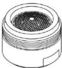
To ensure the opmal temperature output and overall performance of your tankless water heater an aerator supplied with heater should be installed.

DANGER INCREASING THE FLOW RATE REDUCES THE OUTLET TEMPERATURE. PLEASE BE SURE TO ERLY SIZE YOUR AERATOR TO PREVENT SCALDING
7- GENERAL OPERATING INSTRUCTIONS
Operang your new tankless water heater is similar to using any traditional water heang system. However, it is very important that you carefully read all of the setup procedures and operang instrucons and ps to ensure the maximum performance and energy savings from your new water heater. We recommend that all members of the household read these General Operang Instrucons.
How your new water heater works:
This tankless water heater diers from a convenonal storage water heater as it does not store hot water, but heats water as it ows through the heater.
The temperature of the hot water delivered by the heater depends on the waage of the heang element, temperature of the incoming cold water and the water ow rate through the water heater.
It is important to keep in mind that all tankless water heaters are subject to a maximum flow rate. The heater will not be capable of heating water to desired temperature if the flow rate exceeds heaters capability. In order for the heater to operate properly, it must be carefully matched to its application and aerators should be used to limit water flow. See the Table I to determine the maximum flow rates and temperature rise for each model.

CAUTION Outlet water temperature may be higher when using the tankless heater at low ow rates or used with high inlet water temperature.
Water Quality: Quality of water should be taken into consideration when installing and maintaining the water heater. Water conditions outside the recommended levels outlined below are not permitted and can damage the water heater. Manufacture reserves the right to deny any warranty claim regarding damage suffered due to use in water conditions not in accordance with the table below.
If water heater is installed in an area that is known to have hard water that cause scale build-up, the water must be treated and/or the heater exchanger flushed regularly to prevent damage to heat exchanger and/or heating elements.
A water treatment device or water softener should be installed to maintain optimal performance of the water heater in hard water areas. Contact customer service for additional information on these accessory kits.
| Chart for Recommended Water Quality Levels | |||||||||
| pH | Total Dissolved Solids (TDS) | Free Carbon Dioxide (CO2) | Total Hardness | Aluminum | Chloride | Copper | Iron | Manganese | Zinc |
| 6.5 - 8.5 | Up to 500 mg/L | Up to 500 mg/L | Up to 200 mg/L | 0.05 to 0.2 mg/L | Up to 250 mg/L | Up to 1.0 mg/L | Up to 0.3 mg/L | Up to 0.05 mg/L | Up to 5 mg/L |
8- MAINTENANCE
To ensure maximum performance of your water heater and to reduce the risk of a water leak, we recommend the following maintenance:
Inspect the connections on the inlet and outlet of the water heater at least on an annual basis for any signs of damage or failure. Any signs of damage, cracks, leakage or weakness should be addressed. Take care not to over tighten the connections. Serious internal damage to your water heater can occur if you over tighten the water heater connections at the unit.
IMPORTANT NOTES:

DANGER As with all electrical appliances, under no circumstances should you attempt to install, repair or resemble this water heater without first shutting off all power to the unit directly at the fuse or circuiter. SERIOUS BODILY INJURY OR DEATH COULD OCCUR IF YOU IGNORE THIS WARNING.
When any maintenance is performed on the water heater or the home's plumbing system that may introduce air into the plumbing pipes, it is important to turn the power off to the water heater and purge the air out of the lines before allowing the unit to power up. FAILURE TO DO SO COULD CAUSE PERMANENT DAMAGE TO THE HEATING ELEMENT AND VOID YOUR WARRANTY.
If you have a water supply with a high level of mineralization (hard water), you should increase the frequency of your maintenance.
9- TROUBLE SHOOTING GUIDE
Are you having problems with your water heater?
Please call or email our customer service and technical support team for any help you may need.
TOLL FREE 1-(800) 374-8806
The following table represents some of the most common technical support quesons we receive. Before calling us, please read thoroughly to see if your queson or problem is addressed.
| PROBLEM | POSSIBLE CAUSE | SOLUTION |
| Water heater is not heang at all (water is owing but the unit is not heang - the outgoing water temperature is the same as the cold water supply) - the digital display does NOT light up. | No power or incorrect wiring. | Make sure the breakers at main electrical panel are ON. You may have a faulty breaker or unit may be wired incorrectly. |
| Flow rate is too low / water pressure is too low. | Your water heater has an acvaon ow rate of approximately 0.3 GPM (1.1 LPM). If your water ow rate is less than this level, your unit will not acvate. Increase the ow rate. | |
| Water heater is not heang at all (water is owing but the unit is not heang - the outgoing water temperature is the same as the cold water supply) The digital display DOES light up. | Internal part failure. | Please call us for technical assistance. |
| Water heater is heang, but the water temperature is not hot enough. | Flow rate is too high. | Depending on your incoming water temperature and the kW of your heater, your water ow rate may exceed the physical heang capacity of your water heater. Reduce the ow rate by installing an aerator |
| Crossed wires. | If it's a new installaon, have your electrician double check the wiring. Is possible that the wiring is incorrect. | |
| Voltage less than 120 or 240 volts. | The heang elements on your water heater are design for 120 or 240 volts. When used with a lower voltage, they produce less heang power. You may need to upgrade to a larger input heater. | |
| Mixing too much cold water. | You do not need to mix as much cold water with your tankless water heater compared to when you use a convenonal water heater. You may also have an an-scald feature on your faucet that is mixing cold water. These types of faucets can usually be adjusted to reduce the amount of cold water mixed. | |
| Voltage less than 120 or 240 volts. | The computer chips in your tankless water heater are programmed with the expectaon that your incoming line voltage is 120 or 240 volts. If you have less than 120 or 240 volts, it may act the reading on your water heater's digital display and cause it to read slightly higher than the actual output temperature. To compensate for this, increase the seng on your water heater if you need / want hoer water. | |
| The water temperature at the faucet is less or greater than the temperature seng of my water heater. | An-Scald pressure/balancing valve or tempering valve. | Your faucet may have an an-scald feature or a tempering valve that automacally mixes cold water even when you turn your control lever or handle to full hot. These devices are usually adjustable so you can turn o the cold mix completely. You can compensate for this by increasing the seng on your water heater if you need/want hoer water. |
| Thermal loss due to long pipe run | As the hot water from the heater runs through the hot water delivery system to your faucet, some heat will be lost especially if it has long distance to travel or the pipes are cold. This is normal. You can compensate for this by increasing the seng on your water heater if you need/want hoer water. | |
| Water temperature at the faucet is too hot | Check your ow for too lile ow, wrong aerator size, or internal part failure. Call us for technical assistance. | |
10- USER INTERFACE
Power
- Push the power buon, the display will turn on
- Push the power buon again, the display will turn o
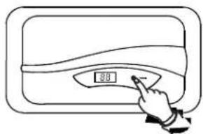
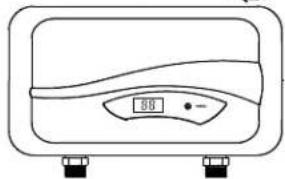
DANGER Hoer water increases the potenal for Hot Water SCALDS
CAUTION – removing the cover to change the temperature set point exposes electrical shock and burn hazards, which can cause INJURY or DEATH. Adjustment should only be done by a licensed plumber or electrician.
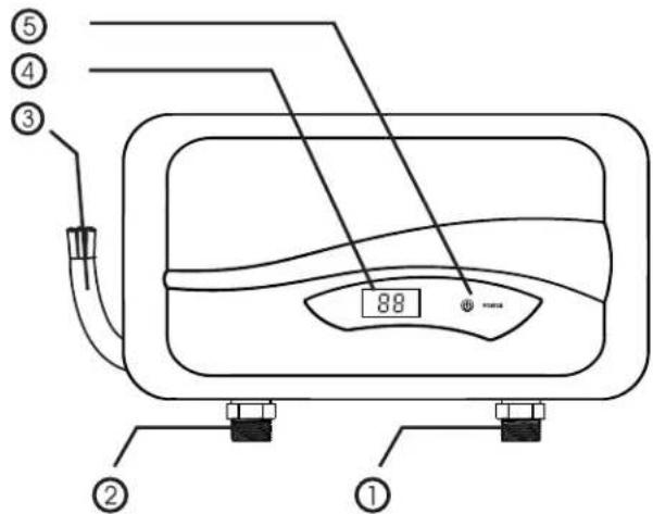
Heater input: 3.5 kW -6.0 kW
① Cold water Inlet
② Hot water outlet
③ 10 AWG Wire
④ Outlet Temp. Display
⑤ POWER button
NOTES
Time/Temperature Relationship in Scalds
| Water Temperature | Time to Produce a Serious Burn |
| 120°F (49°C) | More than 5 minutes |
| 125°F (52°C) | 1 1/2 to 2 minutes |
| 130°F (54°C) | About 30 seconds |
| 135°F (57°C) | About 10 seconds |
| 140°F (60°C) | Less than 5 seconds |
| 145°F (63°C) | Less than 3 seconds |
| 150°F (66°C) | About 1 1/2 seconds |
| 155°F (68°C) | About 1 second |
Table courtesy of Shriners Burn Institute
| Chart for Recommended Water Quality Levels | |||||||||
| pH | Total Dissolved Solids (TDS) | Free Carbon Dioxide (CO2) | Total Hardness | Aluminum | Chloride | Copper | Iron | Manganese | Zinc |
| 6.5 - 8.5 | Up to 500 mg/L | Up to 500 mg/L | Up to 200 mg/L | 0.05 to 0.2 mg/L | Up to 250 mg/L | Up to 1.0 mg/L | Up to 0.3 mg/L | Up to 0.05 mg/L | Up to 5 mg/L |
8 - MANTENIMIENTO
Water temperature over 125°F can cause severe burns instantly or death from scalds.
Children, disabled and elderly are at highest risk of being scalded.
See instruction manual before setting temperature at water heater.
Feel water before bathing or showering.
Temperature limiting valves are available, see manual.
Time/Temperature Relationship in Scalds
| Water Temperature | Time to Produce a Serious Burn |
| 120°F (49°C) | More than 5 minutes |
| 125°F (52°C) | 1 1/2 to 2 minutes |
| 130°F (54°C) | About 30 seconds |
| 135°F (57°C) | About 10 seconds |
| 140°F (60°C) | Less than 5 seconds |
| 145°F (63°C) | Less than 3 seconds |
| 150°F (66°C) | About 1 1/2 seconds |
| 155°F (68°C) | About 1 second |
Table courtesy of Shriners Burn Institute
| Chart for Recommended Water Quality Levels | |||||||||
| pH | Total Dissolved Solids (TDS) | Free Carbon Dioxide (CO2) | Total Hardness | Aluminum | Chloride | Copper | Iron | Manganese | Zinc |
| 6.5 - 8.5 | Up to 500 mg/L | Up to 500 mg/L | Up to 200 mg/L | 0.05 to 0.2 mg/L | Up to 250 mg/L | Up to 1.0 mg/L | Up to 0.3 mg/L | Up to 0.05 mg/L | Up to 5 mg/L |
8- ENTRETIEN
NOTES


- ELECTRIC TANKLESS WATER HEATERS
- IMPORTANT SAFETY INFORMATION
- IMPORTANT SAFETY INFORMATION. READ ALL INSTRUCTIONS BEFORE USING
- DANGER! WATER TEMPERATURE SAFETY SETTING
- DANGER
- CAUTION
- ABOUT YOUR TANKLESS WATER HEATER
- MANUFACTURER'S NAONAL SERVICE DEPARTMENT
- CONTENTS
- BEFORE INSTALLATION
- SELECTING A LOCATION TO INSTALL
- MOUNTING YOUR WATER HEATER
- PLUMBING INSTALLATION
- INSTALLAON INSTRUCONS
- THIS WATER HEATER IS SUPPLIED WITH 1/2 " NPT NGS, DO NOT WELD OR USE PASTE
- IMPORTANT NOTES
- WARNING CHECK FOR LEAKS BEFORE PROCEEDING TO ELECTRICAL INSTALLATION
- ELECTRICAL INSTALLATION
- SIZING GUIDE
- GENERAL OPERATING INSTRUCTIONS
- HOW YOUR NEW WATER HEATER WORKS
- CAUTION OUTLET WATER TEMPERATURE MAY BE HIGHER WHEN USING THE TANKLESS HEATER AT LOW OW RATES OR USED WITH HIGH INLET WATER TEMPERATURE
- MAINTENANCE
- TROUBLE SHOOTING GUIDE
- ARE YOU HAVING PROBLEMS WITH YOUR WATER HEATER
- TOLL FREE 1-(800) 374-8806
- USER INTERFACE
- POWER
- DANGER HOER WATER INCREASES THE POTENAL FOR HOT WATER SCALDS
- NOTES
- MANTENIMIENTO
- ENTRETIEN
Brand : Rheem
Model : RTEX-08
Category : Boiler